-

Win a Free Custom Engraved Brass Coin!!!
As a way to introduce our brass coins to the community, we will raffle off a free coin during the month of August. Follow link ABOVE for instructions for entering.
-

PRE-ORDER SHIPS IN SCALE TODAY!
The beloved Ships in Scale Magazine is back and charting a new course for 2026!
Discover new skills, new techniques, and new inspirations in every issue.
NOTE THAT OUR FIRST ISSUE WILL BE JAN/FEB 2026
- Home
- Forums
- Ships of Scale Group Builds and Projects
- Le Coureur 1776 1:48 PoF Group Build
- Le Coureur 1776 1:48 Group Build Logs
You are using an out of date browser. It may not display this or other websites correctly.
You should upgrade or use an alternative browser.
You should upgrade or use an alternative browser.
LE COUREUR - french Lugger 1776 - POF kit from CAF in 1:48 by Uwe
Yes, really very nicely done. Oh dear, I still have this exciting nail.
Pity, as I have been waiting to see the nailing of the stern planks. Do you know if this would be a mix of metal and treenails, pure metal or . . . ?Many Thanks for the interest - I promise, it will be (for the time) the last Planking and nailing post
Lovely work Uwe. Lets say you got this one nailed. 
Hallo Poul,Pity, as I have been waiting to see the nailing of the stern planks. Do you know if this would be a mix of metal and treenails, pure metal or . . . ?
do you mean this area of the stern marked with red?
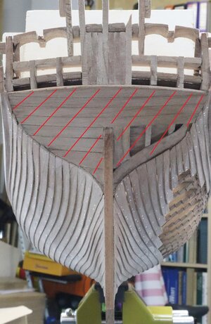
First of all I want to bring the words from @Gilles Korent in post #541 into mind
Planking on Le Coureur
Given the information from the monograph and more specifically the representation of the hull as shown in plate 3, no treenails were used in this vessel. The text does not mention the use of treenails. I would remind the reader that usually (and that may be on larger ships or on carvel planked vessels), below the waterline, the planking was fastened by 1 nail and 1 treenail on each frame. Above the water line, where the planking is not clinker-style, upper-works, 2 nails.
LE COUREUR - french Lugger 1776 - POF kit from CAF in 1:48 by Uwe
I am of course no authority on the matter... nor do I pretend to be an expert. According to documentation (74-gun ship, vol.1) nails, in general, were proportioned as follows: The length of the nails to be used is defined by a ratio indicating that it must penetrate the underlying timber by...
shipsofscale.com
So only bolts and nails, but no treenails - I am still thinking about how I show the fastenings at the stern, but definitely no treenails
- Joined
- Feb 18, 2019
- Messages
- 719
- Points
- 353

Again, no expert...I am still thinking about how I show the fastenings at the stern, but definitely no treenails
But normal planking: 2 nails per plank to each structural timber: same as the upper works.
G
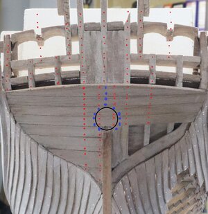
Yes, I meant the area you marked with red (but maybe also the area I have marked with violet although I'm aware that most of the nails in this area will be hidden by decorations).
Most of it I think is more or less obvious but would there be nails in each of the 9 vertical timber in the area I have marked with a black square?
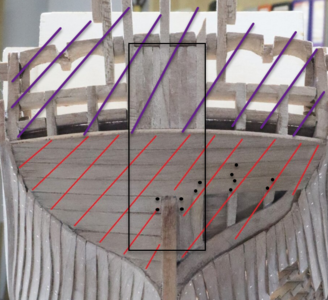
Most of it I think is more or less obvious but would there be nails in each of the 9 vertical timber in the area I have marked with a black square?

- Joined
- Feb 18, 2019
- Messages
- 719
- Points
- 353

Just one comment about the photo shown.Yes, I meant the area you marked with red (but maybe also the area I have marked with violet although I'm aware that most of the nails in this area will be hidden by decorations).
Most of it I think is more or less obvious but would there be nails in each of the 9 vertical timber in the area I have marked with a black square?
View attachment 219128
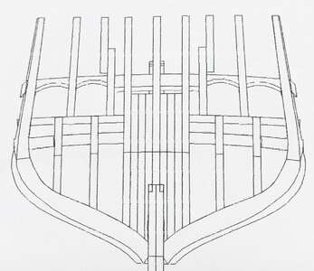
The helm port framing is peculiar with 9 timbers to form a really massive solid piece extended that high in the center of the stern. In reality, I would think that these timbers should only be extended up to the lower transom: basically in line with the top of the red lines. But never mind, that seems to be the way the stern is framed in the kit.
As far as nailing is concerned, what you have seems adequate.
Do not forget to cut the helm port before nailing. Right now you do not have an opening for the rudder to go through. Then, you can take care of the nails.
As for the nails into that solid piece (those 9 timbers in the center): I would only nail the planks to the center and the side timbers. That will give you about the right spacing along with the other vertical timbers. Nails should be installed around opening of the helm port as well unless you plan to install a rudder coat later.
G.
Last edited:
Many Thanks Gilles for the additional information and comments.
Usually it will be all covered by the outside planking of the stern.
The main question, which I did not ake into account until now is the inside view of this part.
As we know, the windows in the stern are no real windows, they are "fake" on the real ship.
When we take a look at Etiennes great model in 1:24 we can see where the level of the deck is ending - appr. in the middle (in height) of the "windows"
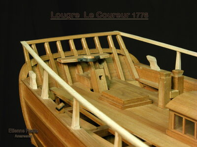
 www.amarsenal.be
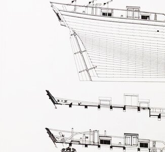
also visible at the Jean Boudriot drawings where we can find a longitudinal cross section of the stern
Now it has to be checked, if these 9 timbers are visible (the 2 times 3 timbers) are shorter than the deck or not? ...... if they are too long, they have to be shortened and sanded down in such way, that they are not visble any more, after the deck planking is done.
Once more Many Thanks for the helpfull comments - Highly appreciated and welcome - so please visit my log as often as possible......
You are right that this would not be so massive in real - I guess it is a reason of stability (of the fragile kit parts) and to make it easier for the modeler.The helm port framing is peculiar with 9 timbers to form a really massive solid piece extended that high in the center of the stern. In reality, I would think that these timbers should only be extended up to the lower transom: basically in line with the top of the red lines. But never mind, that seems to be the way the stern is framed in the kit.
Usually it will be all covered by the outside planking of the stern.
The main question, which I did not ake into account until now is the inside view of this part.
As we know, the windows in the stern are no real windows, they are "fake" on the real ship.
When we take a look at Etiennes great model in 1:24 we can see where the level of the deck is ending - appr. in the middle (in height) of the "windows"

Archéologie et modélisme d'Arsenal (Angleur - Wallonie - Belgique - Europe ) - Le Coureur
AMArsenal - Une association belge qui s'occupe de faire revivre le modélisme naval pratiqué jadis dans les arsenaux. Notre démarche se base sur l'étude des documents anciens et les travaux de l'archéologue et pionnier Jean Boudriot.
also visible at the Jean Boudriot drawings where we can find a longitudinal cross section of the stern

Now it has to be checked, if these 9 timbers are visible (the 2 times 3 timbers) are shorter than the deck or not? ...... if they are too long, they have to be shortened and sanded down in such way, that they are not visble any more, after the deck planking is done.
I will take this into account and will make the nailing after opening the helm port - rudder coat is another challenge - I have planned it and the kit contents also some very fine canvas for this.....Do not forget to cut the helm port before nailing. Right now you do not have an opening for the rudder to go through. Then, you can take care of the nails.
As for the nails into that solid piece (those 9 timbers in the center): I would only nail the planks to the center and the side timbers. That will give you about the right spacing along with the other vertical timbers. Nails should be installed around opening of the helm port as well unless you plan to install a rudder coat later.
Once more Many Thanks for the helpfull comments - Highly appreciated and welcome - so please visit my log as often as possible......
Refering the discussion of the last two days I am studying in moment the drawings and will post here my summary in short time.
It will get really interesting for the modelers building the model......
For the meantime I have an additional information related to the visibility of the interior through the open planking.
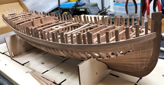
After finishing the planking and the nailing I dryfitted once more the prepared interior walls and floors. When you plan only a partly planking of the hull in order to get some visibility of the interior, please check these photos
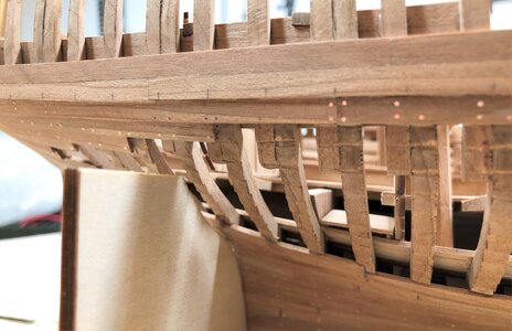
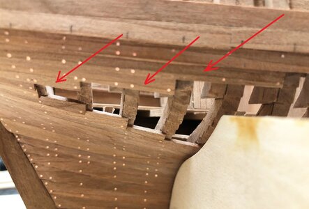
On my next Le Coureur I would also omit the planks which are marked with the red arrows ......
It will get really interesting for the modelers building the model......
For the meantime I have an additional information related to the visibility of the interior through the open planking.
After finishing the planking and the nailing I dryfitted once more the prepared interior walls and floors. When you plan only a partly planking of the hull in order to get some visibility of the interior, please check these photos


On my next Le Coureur I would also omit the planks which are marked with the red arrows ......
In order to plan the order of the final installation I dryfitted the hull with the prepared interior walls and floors.
It took some time for me to remember which wall has to be where, was it for or aft the beams? etc....
but I managed it (somehow) ....... so this is the starting point of the permanent installations
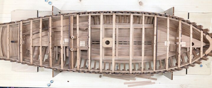
(one midship beam was turned upside down by accident)
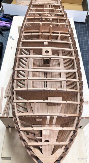
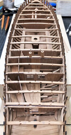
It is getting step by step a nice ship model
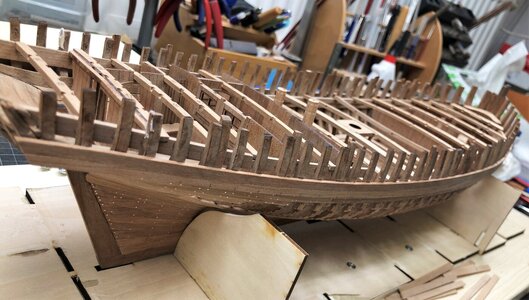
I numbered every beam by the frame numbers and also running from fore to aft
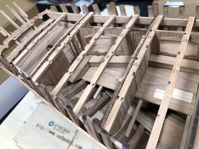
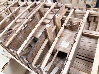
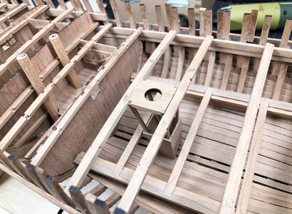
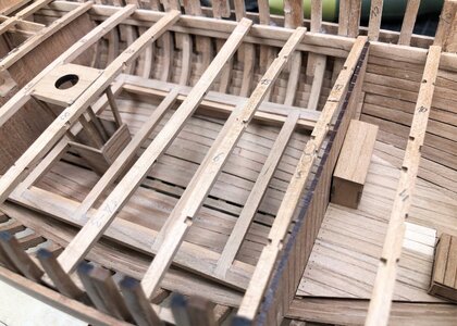
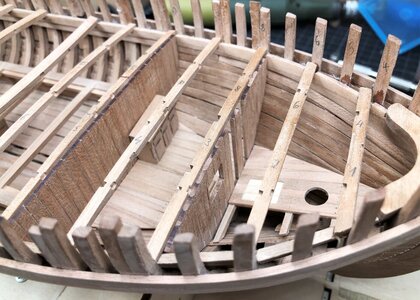
It took some time for me to remember which wall has to be where, was it for or aft the beams? etc....
but I managed it (somehow) ....... so this is the starting point of the permanent installations

(one midship beam was turned upside down by accident)


It is getting step by step a nice ship model


I numbered every beam by the frame numbers and also running from fore to aft


In another building log, we had the talk about the monkey ladder located at the storeroom midships.
The only access to this area via a hatch on the deck - I prepared this small element with a 4 to 4mm and a sharp knife.
Distance of the steps, left to right side is 0,75 cm in the model, so appr. 36cm in real .....
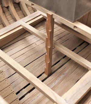
The only access to this area via a hatch on the deck - I prepared this small element with a 4 to 4mm and a sharp knife.
Distance of the steps, left to right side is 0,75 cm in the model, so appr. 36cm in real .....

Hallo Uwe, looks really good, super result. The lack of visibility of the interior because of seemingly too many planks I would not put too high, because in my opinion the overall impression counts. Everything looks very coherent with you. And the monkey ladder, beautifully done and just dinky.
Yes, I meant the area you marked with red (but maybe also the area I have marked with violet although I'm aware that most of the nails in this area will be hidden by decorations).
Most of it I think is more or less obvious but would there be nails in each of the 9 vertical timber in the area I have marked with a black square?
View attachment 219128
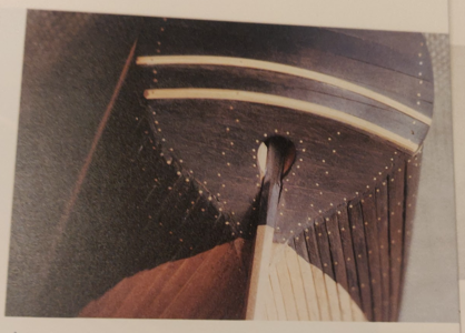
I found in the meantime additional information about the nailing at the stern, which is shown by Jean Boudriot
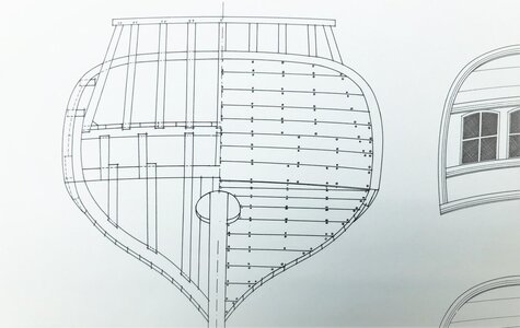
Please have in mind, that the structure of the stern is different from the kit compared to Boudriot. Means if you cover the complete stern with planking,
You can see, that also Boudriot did not make any parallel offset at one beam - the vertical beams are so thin, that they are following one line
So the nailing could look like this: (sorry for the missing parts from the structure - small accidents during planking job, but can be easily repaired)
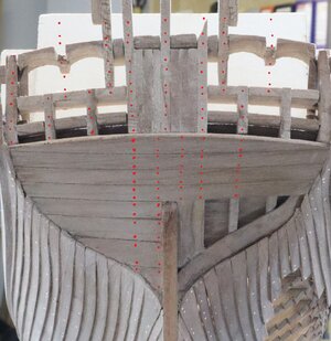
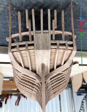
Another possibility would be, that if you completely plank the stern you could also follow the principles by Boudriot
But important is the fact, that you have to take into account, that the area marked with green will be covered and no structure is visible. The area in red will be not visible from the stern, but it will be visible from inside the decks area (see the photo of Etiennes model in post #609) and the area in blue will be fully visible.
So at the end the nailing of the upper part has to follow the alignment of the visible vertical timbers.
You are correct - I forgot once more the helmport openingWell, looking at Boudriot's drawing, Giles' words as well as my own aesthetic perception I think I'll rather make the lower middle section something like the blue dots (around the helm port the nails through the leather)
View attachment 219725
Very good, that you are reminding us on the report in Frölichs book "The Art of Shipmodeling" "L'ART DU MODELISME" "Die Kunst des Modellbaus"Here's is an alternative nailing pattern from Bernard Frohlich. Of course, this is less accurate as he was not working from a PoF model. It sure is purty though.
View attachment 219852
Book review - The Art of Shipmodeling / L'ART DU MODELISME / Die Kunst des Modellbaus" by Bernard FRÖLICH / Frolich
Today I want to bring close to you and highly recommend one book, which has a very special place and importance in my library. L'ART DU MODELISME The Art of Shipmodeling Die Kunst des Modellbaus by Bernard FRÖLICH Hardcover: 304 pages Publisher: www.ancre.fr (2002) Package...
shipsofscale.com
In addition to the photo you are showing
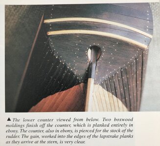
is also the other one some pages later showing the finalized stern with the false windows and the decoration - here we can also see the visible nailing following the vertical posts. On the upper counter he also used nails with slightly bigger diameter..... but I guess this is a question of taste
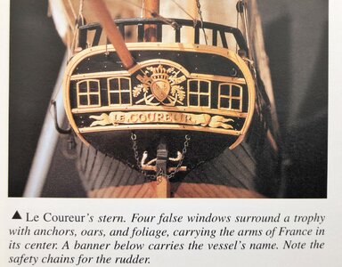
A question of taste is also, if we show nails also in the area between the windows !?! Due to the fact, that they are false windows, the area inside the window frames are the same timber planks, so also here should be nails - not looking so nice, but technically correct.
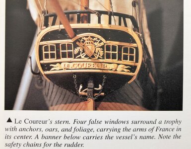
If you want to follow Boudriots information you have theoretically there a vertical structural element, than you have to make a nailAh but there are no frames running through our false windows, so nails in them would not make much sense.
CAF made a different interpretation of the stern structure and prepared the stern structure in such a way, that you can make the windows as open (with glas) and not as Boudriot as false windows out of wood.
Boudriot - without windows and only false windows visible from outside
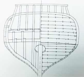
CAF - prepared for windows
