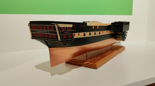
Wow! That is going to look really nice when it all comes together!
-

Win a Free Custom Engraved Brass Coin!!!
As a way to introduce our brass coins to the community, we will raffle off a free coin during the month of August. Follow link ABOVE for instructions for entering.
-

PRE-ORDER SHIPS IN SCALE TODAY!
The beloved Ships in Scale Magazine is back and charting a new course for 2026!
Discover new skills, new techniques, and new inspirations in every issue.
NOTE THAT OUR FIRST ISSUE WILL BE JAN/FEB 2026
You are using an out of date browser. It may not display this or other websites correctly.
You should upgrade or use an alternative browser.
You should upgrade or use an alternative browser.
L'Orenoque Mamoli 1:100 scale
- Thread starter The Gavel
- Start date
- Watchers 27
-
- Tags
- l'orenoque mamoli
- Joined
- Mar 11, 2024
- Messages
- 162
- Points
- 113

Looks like you are bending your mind to it ... i was more occupied with support for model structure rather than full size, gluing the structures direct to the hull seemed a bit flimsy to my mind (it's one of my faults, i tend to overengineer) but i am not sure that the steel support structures you point out were not partly to protect the wheels from floating logs etc. when operating close to shore. It had certainly crossed my mind.
Good morning Chuck. Quality stuff. Going to look fabulous. I missed your Birthday so Happy Belated Birthday Chuck. I hope you had a good one. Cheers GrantWhat ho, shipmates!
I'm giving my self too little time, again. Class in 20 minutes.
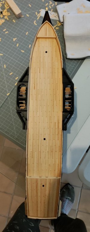
Here's how the sponsons came together: First, the kit plan (shown below) is complete fantasy. I won't repeat the long list of other inaccuracies of the kit sponsons I catalogued in earlier posts. Note the number of supports. Although, I now believe that there were supports for the sponsons, this is too much. None of the available plans for the class of ship (450 hp steam frigate) show the supports, but the models of smaller ships show a more elegant solution which I intend to replicate. That solution was iron rather than huge balks of timber. I wrote that "I now believe" that some support is necessary because before I hadn't thought of the weight of the bateaux tambours, almost 2.5 tons sitting outboard atop the sponsons. Martin @Martin By Eye, I know that we discussed the issue an were thinking perhaps the weight could have been born without lower supports because the sponsons were so stoutly attached to the fabric of the hull and the bulwarks.
View attachment 554802
Below is a shot of the basic parts of my sponson solution. Upper left - red arrows - I built a frame to sit over the wheels with the inboard side resting on top of the bulwark and against the side of the ship (I added scrap to the inboard side of the wheels so that I had 1/16" clearance between the wheel and the interior of the housing inboard. Next - blue arrows - show the separate fore and aft water closet structures with the one aft having a gangway for coming aboard in accordance with the original plan. I built these structures and then glued the forward structure to the larger box. Once I was satisfied the glue was dry and things were still mainly level and square, I glued the aft structure to the whole. The result was a complete structure that can be removed without problem while I work on the rest of the ship. Next - magenta arrows - the water closed tops and the light green arrows pointing at the aft structure and pointing out the scuppers - there are scuppers on the forward water closet as well - had to see in this picture.
View attachment 554803
That's it for the moment. I gotta go teach


A nice puzzle to get all the parts together, Chuck.What ho, shipmates!
I'm giving my self too little time, again. Class in 20 minutes.
Here's how the sponsons came together: First, the kit plan (shown below) is complete fantasy. I won't repeat the long list of other inaccuracies of the kit sponsons I catalogued in earlier posts. Note the number of supports. Although, I now believe that there were supports for the sponsons, this is too much. None of the available plans for the class of ship (450 hp steam frigate) show the supports, but the models of smaller ships show a more elegant solution which I intend to replicate. That solution was iron rather than huge balks of timber. I wrote that "I now believe" that some support is necessary because before I hadn't thought of the weight of the bateaux tambours, almost 2.5 tons sitting outboard atop the sponsons. Martin @Martin By Eye, I know that we discussed the issue an were thinking perhaps the weight could have been born without lower supports because the sponsons were so stoutly attached to the fabric of the hull and the bulwarks.
View attachment 554802
Below is a shot of the basic parts of my sponson solution. Upper left - red arrows - I built a frame to sit over the wheels with the inboard side resting on top of the bulwark and against the side of the ship (I added scrap to the inboard side of the wheels so that I had 1/16" clearance between the wheel and the interior of the housing inboard. Next - blue arrows - show the separate fore and aft water closet structures with the one aft having a gangway for coming aboard in accordance with the original plan. I built these structures and then glued the forward structure to the larger box. Once I was satisfied the glue was dry and things were still mainly level and square, I glued the aft structure to the whole. The result was a complete structure that can be removed without problem while I work on the rest of the ship. Next - magenta arrows - the water closed tops and the light green arrows pointing at the aft structure and pointing out the scuppers - there are scuppers on the forward water closet as well - had to see in this picture.
View attachment 554803
That's it for the moment. I gotta go teach


Regards, Peter
- Joined
- May 25, 2020
- Messages
- 1,147
- Points
- 443

What ho, shipmates!
It's Friday evening at Shangri-la and I don't teach again for a week! Don't get me wrong. I LOVE my gig, but it is nice to have some time to focus on other important and life-giving work
Here are some pics of how the pieces came together. Note: one of the more helpful tools I've discovered is a nice thick piece of glass. I glued the sub-parts of all of the sponson components together on glass! I hope the pics are self explanatory. Happy to give more informatio if requested.
Ok. The pictures are not in perfect order. I'll leave it to you to puzzel it out I know that the screen mesh I amusing for gratings is way out of scale. It looks a bit better painted.
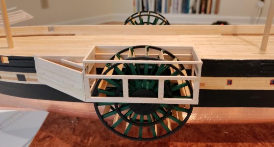
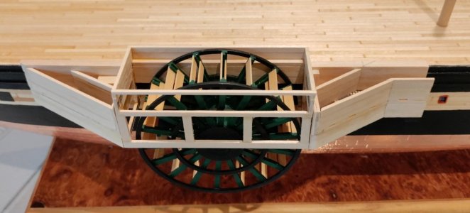
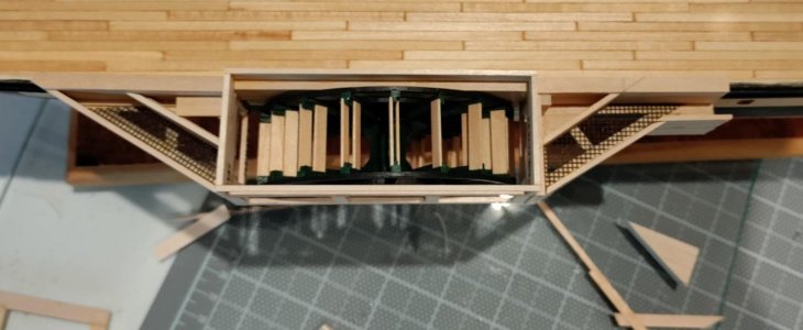
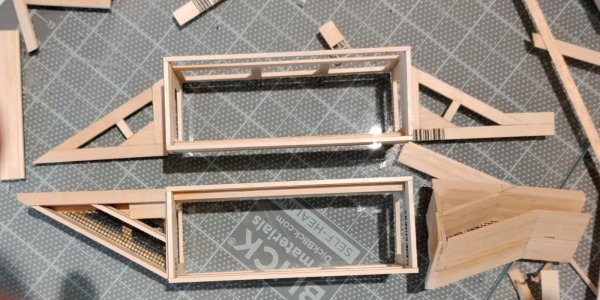
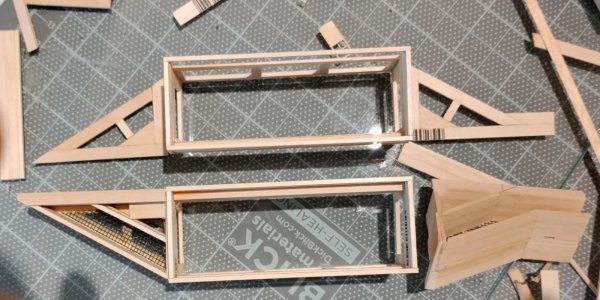
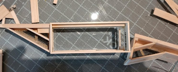
It's Friday evening at Shangri-la and I don't teach again for a week! Don't get me wrong. I LOVE my gig, but it is nice to have some time to focus on other important and life-giving work
Here are some pics of how the pieces came together. Note: one of the more helpful tools I've discovered is a nice thick piece of glass. I glued the sub-parts of all of the sponson components together on glass! I hope the pics are self explanatory. Happy to give more informatio if requested.
Ok. The pictures are not in perfect order. I'll leave it to you to puzzel it out
 I know that the screen mesh I amusing for gratings is way out of scale. It looks a bit better painted.


Last edited:
- Joined
- May 25, 2020
- Messages
- 1,147
- Points
- 443

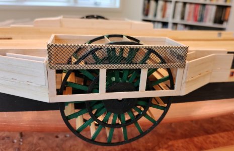
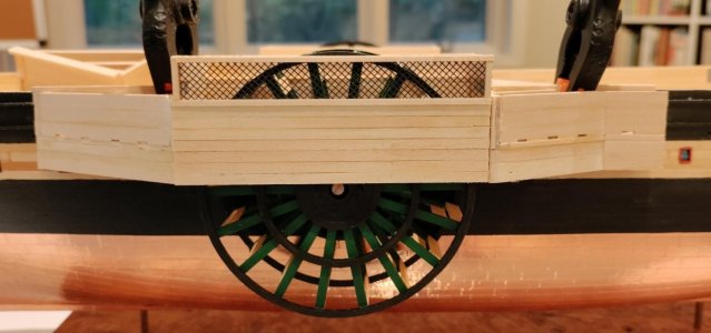
Here are a couple of pics focusing on the lattice on the upper part of the wheel covering box. Again, the screen mesh is not to scale. Once painted it is much better, but still not to scale. I like that the wheels are more visible through the non-scale lattice. Not just a rationalization . You'll see.


- Joined
- May 25, 2020
- Messages
- 1,147
- Points
- 443

After I got the major components finished and fitted, I had to put doors on the fore and aft parts so that sailors could go out onto the sponsons and personnel could get onto the main deck from the aft gangway.
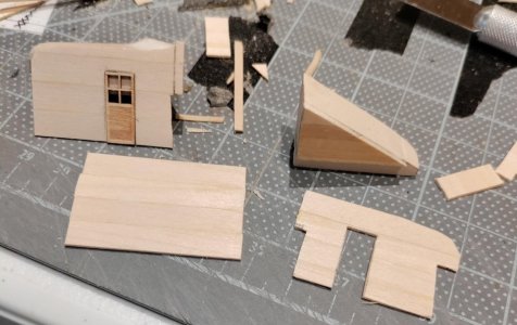
Once I had a skin with the cut out for the door, I glued the skin to the top part of what I am calling the w/c and then glued that part to the sponson assembly. Then, time to paint.
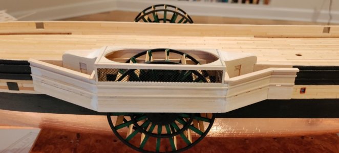
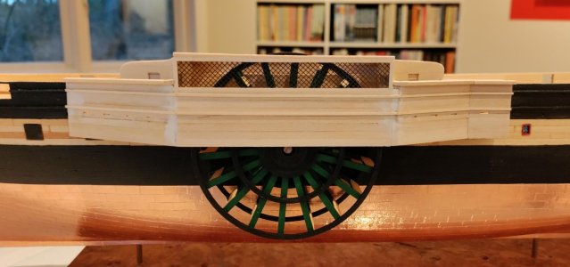
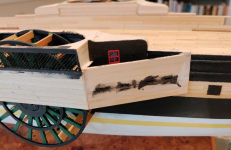
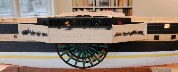
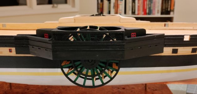
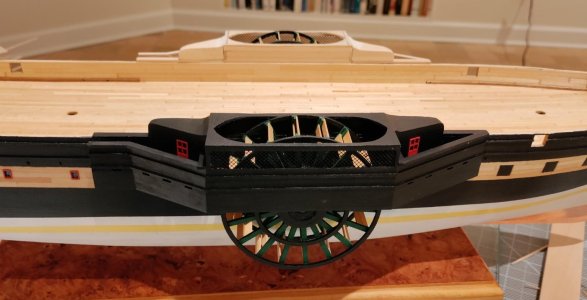


Once I had a skin with the cut out for the door, I glued the skin to the top part of what I am calling the w/c and then glued that part to the sponson assembly. Then, time to paint.


- Joined
- May 25, 2020
- Messages
- 1,147
- Points
- 443

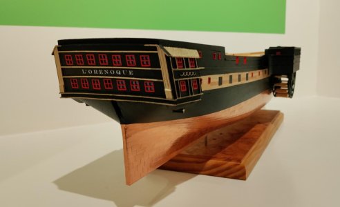
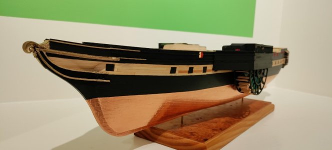
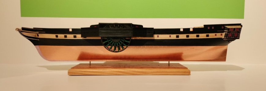
And, shipmates, as we come to the close of this session: I finished coppering the hull and added her name to her stern and painted the open gun ports red.
A few posts back Paul @dockattner asked whether I would repeat the green on the wheels elsewhere. Paul, I'd like to do that. I am thinking the gun carriages and the doors on the inboard parts of the sponsons and maybe the ladders and the bridge. I also thought to paint the funnel that lovely green. We'll see - I'd be glad to have my shipmates' thoughts. I think painting the funnel other than black may be too far out of touch with historical accuracy. Whether that impacts my decisions is anyone's guess
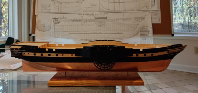

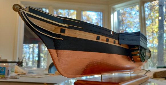
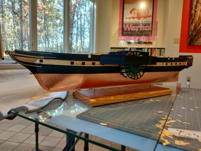
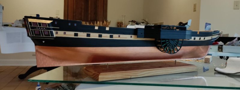
A few posts back Paul @dockattner asked whether I would repeat the green on the wheels elsewhere. Paul, I'd like to do that. I am thinking the gun carriages and the doors on the inboard parts of the sponsons and maybe the ladders and the bridge. I also thought to paint the funnel that lovely green. We'll see - I'd be glad to have my shipmates' thoughts. I think painting the funnel other than black may be too far out of touch with historical accuracy. Whether that impacts my decisions is anyone's guess


Brilliant assembly, Chuck. This is some first class modeling you are showing us!
Brilliant, as usual! You are right: that mesh works very well. WRT the funnel, perhaps a compromise: paint the funnel black, but with a couple of green rings.And, shipmates, as we come to the close of this session: I finished coppering the hull and added her name to her stern and painted the open gun ports red.
A few posts back Paul @dockattner asked whether I would repeat the green on the wheels elsewhere. Paul, I'd like to do that. I am thinking the gun carriages and the doors on the inboard parts of the sponsons and maybe the ladders and the bridge. I also thought to paint the funnel that lovely green. We'll see - I'd be glad to have my shipmates' thoughts. I think painting the funnel other than black may be too far out of touch with historical accuracy. Whether that impacts my decisions is anyone's guess
View attachment 555415View attachment 555416View attachment 555417View attachment 555418View attachment 555419View attachment 555420
Marvelous !
- Joined
- Jun 29, 2024
- Messages
- 1,522
- Points
- 438

Up to your usual high standards, Chuck.
Roger
Roger
- Joined
- Jun 17, 2021
- Messages
- 3,202
- Points
- 588

Oooh la la! Cest magnifique 


Nice build and very elegant. Love the coppering as well.
Very stylish cabinet and an eclectic collection.What ho, shipmates!
I am sorry for the long delays between posts and leaving your kind comments hanging out there without a proper response. Please know that I will send you each the individual response you deserve. In the end, I never fail to meet kindness with kindness.
So, as I warned you, the new academic year with a reborn Professor Henson has been a terrific distraction from my hobbies. AND THEN THE ADMIRAL SAID: "Honey, please make me a desk." So I made the desk and a book case inspiried by Mondiran.
View attachment 550264View attachment 550265View attachment 550266View attachment 550267View attachment 550268
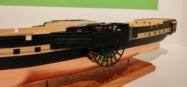
That color combination with the copper plates is looking very nice, Chuck. With a lasting beautiful view of a large part of the paddles under the wheel houses.And finally - some beauty shots
View attachment 555422View attachment 555423View attachment 555424View attachment 555425
View attachment 555421
Regards, Peter
Brilliant Chuck. Way to go. Cheers GrantAnd finally - some beauty shots
View attachment 555422View attachment 555423View attachment 555424View attachment 555425
View attachment 555421


