Thank you very much! I guess you, like I, do not agree with Anderson's statement "Artificially 'bellying' sails may look artistic on a purely decorate model, but on a real scale-built model they are an abomination."Your sails are exceptional. They give life and animation to your model. More like sculpture, very animated and aesthetically pleasing.
-

Win a Free Custom Engraved Brass Coin!!!
As a way to introduce our brass coins to the community, we will raffle off a free coin during the month of August. Follow link ABOVE for instructions for entering.
-

PRE-ORDER SHIPS IN SCALE TODAY!
The beloved Ships in Scale Magazine is back and charting a new course for 2026!
Discover new skills, new techniques, and new inspirations in every issue.
NOTE THAT OUR FIRST ISSUE WILL BE JAN/FEB 2026
You are using an out of date browser. It may not display this or other websites correctly.
You should upgrade or use an alternative browser.
You should upgrade or use an alternative browser.
MarisStella Ragusian Carrack by Signet [COMPLETED BUILD]
- Joined
- Jun 17, 2021
- Messages
- 3,202
- Points
- 588

Mr. Anderson is entitled to his opinion. I rest on mine.Thank you very much! I guess you, like I, do not agree with Anderson's statement "Artificially 'bellying' sails may look artistic on a purely decorate model, but on a real scale-built model they are an abomination."
- Joined
- Jun 17, 2021
- Messages
- 3,202
- Points
- 588

I wonder if Mr. Anderson has ever seen Henry Culver's model of the Sovereign of the Seas at the U.S.N.A. museum?
It is as fine a work of historically documenting a ship by modeling as it is an artistic masterpiece. But then, who am I to pronounce such assessments?
It is as fine a work of historically documenting a ship by modeling as it is an artistic masterpiece. But then, who am I to pronounce such assessments?
WELL DONE MATT- Bolt ropes are well done madeThe mainsail was quite the project for me. Again, for the most part I'm only showing the results; all of you know how to rig far better than I.
The mainsail and bonnet after sewing the boltrope in place:
View attachment 427292
I figured that like most Catholic nations in the Mediterranean, the first few words of the "Ave Maria" would be lettered on the sail to help align the bonnet to the mainsail. I originally translated the words to Croatian, but then remembered that all nations would use Latin from the Catholic church.
View attachment 427293
Here the bonnet has been attached to the mainsail (thank goodness for the "Ave Maria" or I'd probably have screwed that up.
View attachment 427294
I went ahead an made up the parrel for mounting. I'm not certain that design parrel would have been used, but like the looks of it, so...
Using Olha's method for shaping and stiffening sails, this was the result:
View attachment 427295
View attachment 427296
View attachment 427297
The edges had "crinkled" down some, so I re-wet them to activate the starch, and hung the sail by its edge using clamps for weights to take them out:
View attachment 427298
I think the curve came out pretty well:
View attachment 427299
I mounted the sail using a pin for more strength, then attached the halyard and parrel lift, then the clewlines, slablines, lifts and leechlines, which did not depend on the angle or fore-to-aft placement of the sail. Finally, added the sheets, tacks, braces and bowlines, to determine the final location of the sail. And this is the result:
View attachment 427300
View attachment 427301
View attachment 427302
View attachment 427303
View attachment 427304 View attachment 427305
View attachment 427306
View attachment 427307
View attachment 427308
View attachment 427309
Next, the topsail...
A nicely detailed and presented sail! Bravo!
On to the topsail. I decided to work on all three of the remaining sails at the same time. The sails included with the model have a border around the outside which is folded over:
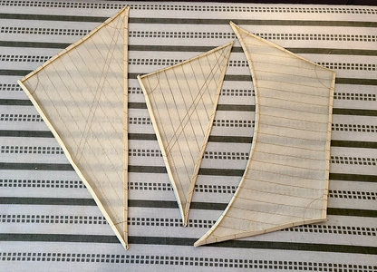
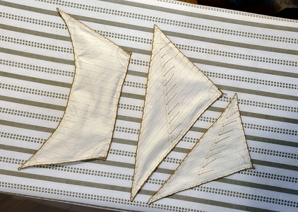
The center sail is the bonaventure lateen sail, which was not included with the kit, but rather made by me using scrap sailcloth from the kit. The thread used is close to the same color as the rest, but is not as shiny or reflective as on the kit sails, so looks darker. The difference seems not that great in person. As before, I inserted #22 black annealed wire in the hem to help shape the sails, and then sewed the overlapping hems all around.
Using the larger lateen sail as an example, I first glue the boltrope in place and (sometimes) let the glue dry. Most often I don't wait, resulting in glue sticking to my fingers (which is satisfying to peel off over time), but it's best to wait, of course.
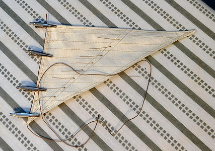
In process of sewing the boltrope in place:
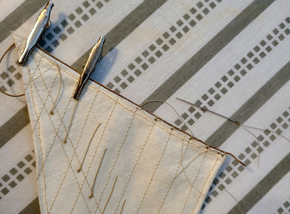
I personally like this method of attachment. It is very close to what has been documented in the kit instructions as being used at the time, and I've seen similar methods published elsewhere, but rather than separate each triple stich being tied off and separated, the thread is pulled from back to front over the boltrope, further holding it in place, between each triple stitch. I like the appearance and to me, at least, it makes sense.
Continuing along the next sail edge, to encircle the sail:
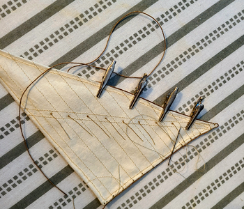
The three remaining sails with boltrope in place, prior to attaching to the spars:
I won't bore you, nor expose my poor rigging workmanship any further, by posting in-process rigging photos, but here are a few views showing the topsail and rigging in place:
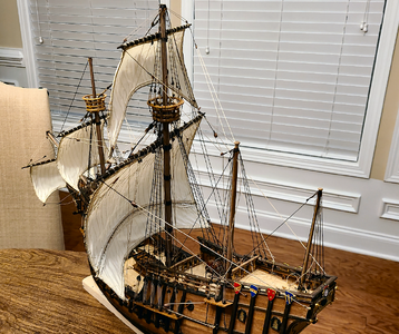
There isn't as much "bow" due to the wind on this sail, due to it being held more tightly by the violin blocks attached to the main course spar, it's smaller area and its severe arc in the sail foot. I have some fine-tuning of bending the wire a bit, but it will get mis-bent during construction, show I'll wait a bit.
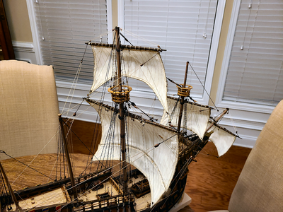
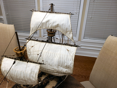
This model is really testing my 80-year old fingers and agility (or lack of same) with the rigging, constantly not having enough room for hands and fingers, plucking other rigging, etc. This will be my one-and-only full rigged ship model (since I was in my teens, anyhow), and I'm glad it's not the more complex rigging of larger ships. I just marvel at Olha's videos, making knots and tying belaying pins like they were full size in front of her, but that's not happening here.
The mizzen lateen spar, sail and rigging are next. I'm hoping the rigging connections will be easier to reach with them. Until next time!

The center sail is the bonaventure lateen sail, which was not included with the kit, but rather made by me using scrap sailcloth from the kit. The thread used is close to the same color as the rest, but is not as shiny or reflective as on the kit sails, so looks darker. The difference seems not that great in person. As before, I inserted #22 black annealed wire in the hem to help shape the sails, and then sewed the overlapping hems all around.
Using the larger lateen sail as an example, I first glue the boltrope in place and (sometimes) let the glue dry. Most often I don't wait, resulting in glue sticking to my fingers (which is satisfying to peel off over time), but it's best to wait, of course.

In process of sewing the boltrope in place:

I personally like this method of attachment. It is very close to what has been documented in the kit instructions as being used at the time, and I've seen similar methods published elsewhere, but rather than separate each triple stich being tied off and separated, the thread is pulled from back to front over the boltrope, further holding it in place, between each triple stitch. I like the appearance and to me, at least, it makes sense.
Continuing along the next sail edge, to encircle the sail:

The three remaining sails with boltrope in place, prior to attaching to the spars:

I won't bore you, nor expose my poor rigging workmanship any further, by posting in-process rigging photos, but here are a few views showing the topsail and rigging in place:

There isn't as much "bow" due to the wind on this sail, due to it being held more tightly by the violin blocks attached to the main course spar, it's smaller area and its severe arc in the sail foot. I have some fine-tuning of bending the wire a bit, but it will get mis-bent during construction, show I'll wait a bit.


This model is really testing my 80-year old fingers and agility (or lack of same) with the rigging, constantly not having enough room for hands and fingers, plucking other rigging, etc. This will be my one-and-only full rigged ship model (since I was in my teens, anyhow), and I'm glad it's not the more complex rigging of larger ships. I just marvel at Olha's videos, making knots and tying belaying pins like they were full size in front of her, but that's not happening here.
The mizzen lateen spar, sail and rigging are next. I'm hoping the rigging connections will be easier to reach with them. Until next time!
Beautiful Signet. Very nice work.
DittoBeautiful Signet. Very nice work.
Thank you so much, I really appreciate it!wonderful work on the sails
- Joined
- Dec 16, 2016
- Messages
- 1,192
- Points
- 493

Hi Signet, I’ve just caught up with your build, again I’m very impressed with your work, I think that you’ve a very good eye for how things should look. Again an interesting and informative log, one that I think I can benefit from, keep up the great work.Thank you so much, I really appreciate it!
Thank you very much, Ken. It has been an enjoyable build for me. Most difficult for me has been getting inside the rigging to make the rope attachments. My fingers and lack of expertise has really made that hard. Luckily, this will be the last rigged ship I will do, going I think to an admiralty build for my next project.Hi Signet, I’ve just caught up with your build, again I’m very impressed with your work, I think that you’ve a very good eye for how things should look. Again an interesting and informative log, one that I think I can benefit from, keep up the great work.
Continuing on to the lateen mizzen sail, I won't bore you with the details and connections, as you all know them better than I, but here are the results:
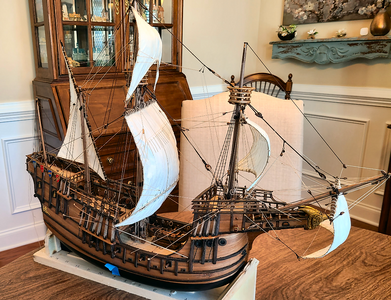
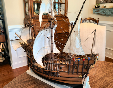
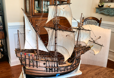
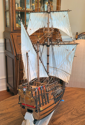
I had a lot of problems rigging the ropes to the various connection points on the deck. Even with some purchased rigging tools, I might spend half an hour on a single rope connection, and even then it only stays because of a blob of super glue. I'm afraid you won't find me posting any close-ups of this work like Olha and others have. But between my eyes, my fingers and my lack of sufficient skills, it's pretty sloppy. But stand back, and look from afar, and it looks pretty good, I think.
The blue tape marks the center-of-gravity of the model, as I've been working on the display stand. I'll probably post it next. And then on to the last sail - the bonaventure sail, which I believe is a first for those modeling this ship, so it will make it a bit different at least. Until next time.
Your build is fantastic!
Super progress, your sails look just great, well done.
I decided to work on the stand for this model next. I based this design on Olha's design for the stand for her Carrack.
I don't have access to a jig saw, so I joined a woodworking friend at a local tool show, showed up with my piece of walnut with the shape drawn on, and conned one of the demonstrators to rough it out for me. The result was better than I'd have been able to do, took less time and made for an interesting show. The result:
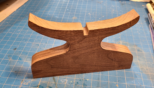
I used a contour gauge to measure the hull contour amidships. I purposely left added height of this piece at the bottom because I couldn't yet determine the exact height.
I would have liked the longitudinal piece of the stand to be longer and wider, but I instead used some walnut I had on hand from different project (if I ever decide to build that carriage clock I designed, I'll have to find another piece). I got brass pedestals to use for the base, and the height of them (45mm) plus the longitudinal piece of walnut would determine the height of the stand:
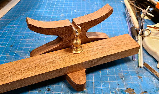
This would help determine how much to cut off the bottom of the crosspiece.
After routing the edges with a 1/4" round bit, the pieces start to look a bit better:
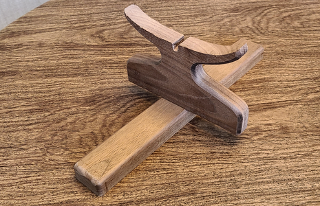
I also realized that while I had a decent contour for the bottom of the hull, I really had no reference to vertical. That is, while I centered the contour as best I could, the keel would determine the actual location side-to-side, and that in fact could rotate the whole model. So I balanced the ship model on the crosspiece (yeah, my whole almost-complete model on a 3/4" wide piece - nerves ), and measured the angle of the mainmast, which should be 90 degrees. Turned out, surprisingly, that it was very close: 89.6 degrees (per digital device). Even though this is very close, it still meant it was off by 1mm across the 6" width. I did my best measurements of the amount to trim off the bottom of the crosspiece, and marked it, at the required angle, with tape to help make an accurate cut:
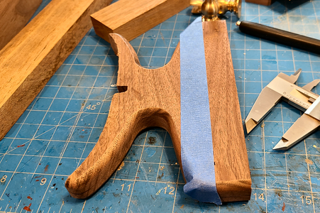
I then notched both pieces for a secure connection using a table saw:
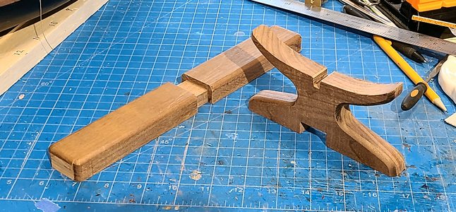
I actually mis-measured the bottom notch on the crosspiece, so it ended up off-center. That turned out to be a good thing, because when then re-checking everything I realized that simply centering the crosspiece and the pedestals was no guarantee that the line between them would be exactly straight and properly fit the keel.
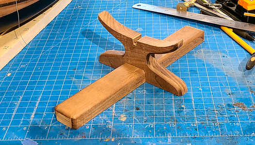
Placing and centering the pedestals brought this to light:
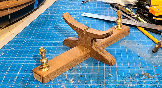
I therefore widened the slot in the crosspiece so as to allow it to move far enough to be centered. Using a piece of 6mm walnut from the kit sheet containing the keel, I used it to find the correct location to have everything in line:
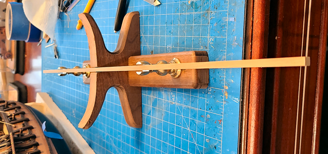
Sorry if tilting your head to look at this hurts; it did hurt my neck, but takes up less space this way.
Using this position, I then glued the crosspiece in place, adding weights to hold everything tight:
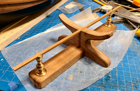
You'll notice that sanding had been done at this point.
After the glue dried, I filled the gaps and placed two screws to hold the assembly better together:
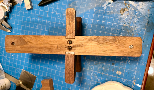
After two coats of Minwax Rub-On Poly, we have the completed stand:
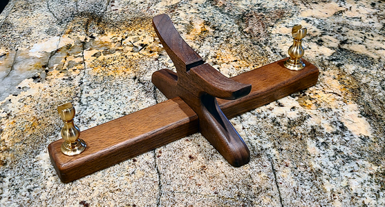
I added felt to cover the bottom, as well as the curved portion contacting the hull. The final result, with the ship model in place, looks like this:
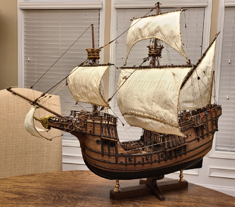
So, that will work for me. The stand couldn't have been that much longer, holds the model securely but is easily removed, looks good but doesn't detract from the model itself. That will do.
Now, about that bonaventure sail.....
I don't have access to a jig saw, so I joined a woodworking friend at a local tool show, showed up with my piece of walnut with the shape drawn on, and conned one of the demonstrators to rough it out for me. The result was better than I'd have been able to do, took less time and made for an interesting show. The result:

I used a contour gauge to measure the hull contour amidships. I purposely left added height of this piece at the bottom because I couldn't yet determine the exact height.
I would have liked the longitudinal piece of the stand to be longer and wider, but I instead used some walnut I had on hand from different project (if I ever decide to build that carriage clock I designed, I'll have to find another piece). I got brass pedestals to use for the base, and the height of them (45mm) plus the longitudinal piece of walnut would determine the height of the stand:

This would help determine how much to cut off the bottom of the crosspiece.
After routing the edges with a 1/4" round bit, the pieces start to look a bit better:

I also realized that while I had a decent contour for the bottom of the hull, I really had no reference to vertical. That is, while I centered the contour as best I could, the keel would determine the actual location side-to-side, and that in fact could rotate the whole model. So I balanced the ship model on the crosspiece (yeah, my whole almost-complete model on a 3/4" wide piece - nerves
 ), and measured the angle of the mainmast, which should be 90 degrees. Turned out, surprisingly, that it was very close: 89.6 degrees (per digital device). Even though this is very close, it still meant it was off by 1mm across the 6" width. I did my best measurements of the amount to trim off the bottom of the crosspiece, and marked it, at the required angle, with tape to help make an accurate cut:
I then notched both pieces for a secure connection using a table saw:

I actually mis-measured the bottom notch on the crosspiece, so it ended up off-center. That turned out to be a good thing, because when then re-checking everything I realized that simply centering the crosspiece and the pedestals was no guarantee that the line between them would be exactly straight and properly fit the keel.

Placing and centering the pedestals brought this to light:

I therefore widened the slot in the crosspiece so as to allow it to move far enough to be centered. Using a piece of 6mm walnut from the kit sheet containing the keel, I used it to find the correct location to have everything in line:

Sorry if tilting your head to look at this hurts; it did hurt my neck, but takes up less space this way.
Using this position, I then glued the crosspiece in place, adding weights to hold everything tight:

You'll notice that sanding had been done at this point.
After the glue dried, I filled the gaps and placed two screws to hold the assembly better together:

After two coats of Minwax Rub-On Poly, we have the completed stand:

I added felt to cover the bottom, as well as the curved portion contacting the hull. The final result, with the ship model in place, looks like this:

So, that will work for me. The stand couldn't have been that much longer, holds the model securely but is easily removed, looks good but doesn't detract from the model itself. That will do.
Now, about that bonaventure sail.....
Last edited:
wow - two weeks not looking at your log - and the sails are almost finished - the sails are very good
and I agree also with your opinion about the stand - it is fitting very well with this type of ship - I like it - and btw very good executed
and I agree also with your opinion about the stand - it is fitting very well with this type of ship - I like it - and btw very good executed
Last edited:
- Joined
- Jun 17, 2021
- Messages
- 3,202
- Points
- 588

Agreed!wonderful work on the sails
Perfection! Wonderful model, perfect presentation. Congratulations!I decided to work on the stand for this model next. I based this design on Olha's design for the stand for her Carrack.
I don't have access to a jig saw, so I joined a woodworking friend at a local tool show, showed up with my piece of walnut with the shape drawn on, and conned one of the demonstrators to rough it out for me. The result was better than I'd have been able to do, took less time and made for an interesting show. The result:
View attachment 432402
I used a contour gauge to measure the hull contour amidships. I purposely left added height of this piece at the bottom because I couldn't yet determine the exact height.
I would have liked the longitudinal piece of the stand to be longer and wider, but I instead used some walnut I had on hand from different project (if I ever decide to build that carriage clock I designed, I'll have to find another piece). I got brass pedestals to use for the base, and the height of them (45mm) plus the longitudinal piece of walnut would determine the height of the stand:
View attachment 432403
This would help determine how much to cut off the bottom of the crosspiece.
After routing the edges with a 1/4" round bit, the pieces start to look a bit better:
View attachment 432404
I also realized that while I had a decent contour for the bottom of the hull, I really had no reference to vertical. That is, while I centered the contour as best I could, the keel would determine the actual location side-to-side, and that in fact could rotate the whole model. So I balanced the ship model on the crosspiece (yeah, my whole almost-complete model on a 3/4" wide piece - nerves), and measured the angle of the mainmast, which should be 90 degrees. Turned out, surprisingly, that it was very close: 89.6 degrees (per digital device). Even though this is very close, it still meant it was off by 1mm across the 6" width. I did my best measurements of the amount to trim off the bottom of the crosspiece, and marked it, at the required angle, with tape to help make an accurate cut:
View attachment 432406
I then notched both pieces for a secure connection using a table saw:
View attachment 432407
I actually mis-measured the bottom notch on the crosspiece, so it ended up off-center. That turned out to be a good thing, because when then re-checking everything I realized that simply centering the crosspiece and the pedestals was no guarantee that the line between them would be exactly straight and properly fit the keel.
View attachment 432408
Placing and centering the pedestals brought this to light:
View attachment 432409
I therefore widened the slot in the crosspiece so as to allow it to move far enough to be centered. Using a piece of 6mm walnut from the kit sheet containing the keel, I used it to find the correct location to have everything in line:
View attachment 432410
Sorry if tilting your head to look at this hurts; it did hurt my neck, but takes up less space this way.
Using this position, I then glued the crosspiece in place, adding weights to hold everything tight:
View attachment 432411
You'll notice that sanding had been done at this point.
After the glue dried, I filled the gaps and placed two screws to hold the assembly better together:
View attachment 432412
After two coats of Minwax Rub-On Poly, we have the completed stand:
View attachment 432413
I added felt to cover the bottom, as well as the curved portion contacting the hull. The final result, with the ship model in place, looks like this:
View attachment 432414
So, that will work for me. The stand couldn't have been that much longer, holds the model securely but is easily removed, looks good but doesn't detract from the model itself. That will do.
Now, about that bonaventure sail.....


