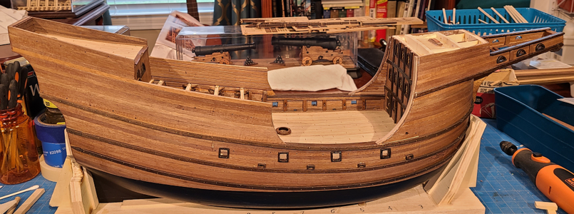
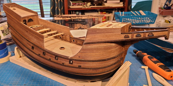
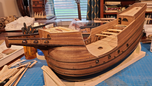
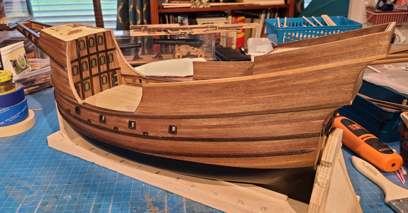
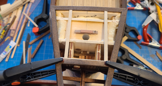
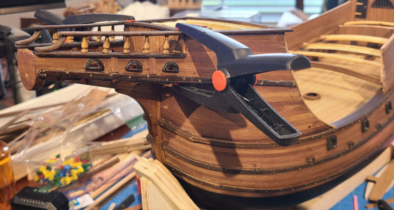
MarisStella Ragusian Carrack by Signet [COMPLETED BUILD]

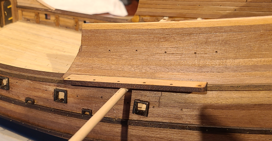
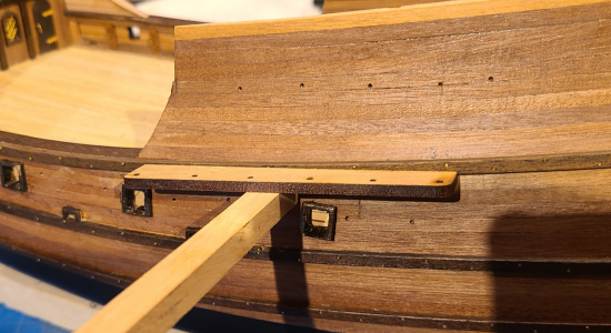
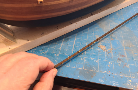
I ended up adding the 0.6x4mm pieces at the bottom which neatened up the appearance some (pics later). I also installed the two rubbing strakes just below the main deck level and water drains. I stained the two 2x4 pieces after drilling the holes for the nails, then inserted the nails prior to gluing and nailing in place:
1683661669365.png
My intention was to position it, use a brad/nail pusher, and it did a good job except when it slipped and damaged the nail, hull and strake :-(. I then resorted to a hammer, which worked in most cases, and did less damage when it bent a nail.

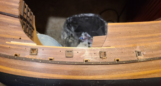
Here you can see one of the strakes installed, as well as work on the gunports:
1683662043592.png
I used the same method on the gunports as on the drains: gluing the port surround in place, drilling small holes at each corner and in between, then filing out the opening, filing the inside of the surround at the same time.

While I drilled holes, as shown previously, marking the location of the gun ports and other items, I measured up from the deck to determine the gunport locations for the guns. With most previous kits I've done, the ports are never in the right position when I do the per the plan.

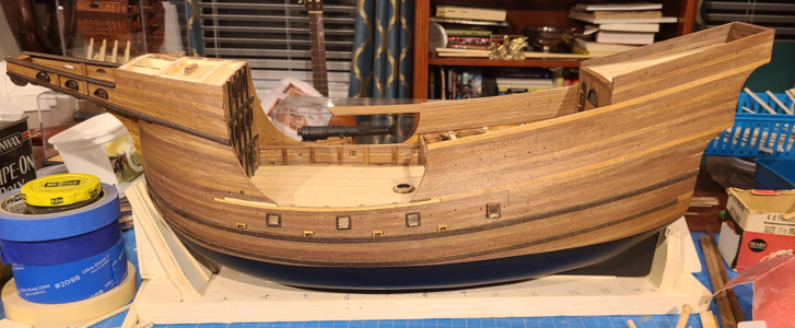
In general, the overall appearance is okay. I'm getting more and more poor quality or poorly done areas, but have to be a bit realistic in what to spend time on and what will show. My 80th birthday today and everything hurts, like it has for a while.
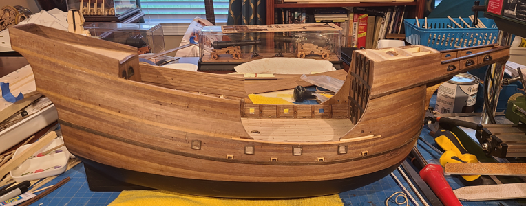
1683662840169.png
No more strakes to be done for now; I've ordered more tiny nails, which won't be here for a week or so. Trying to decide what to work on next.

I'm getting a cheap WEN scroll saw for my birthday (so I understand). I'm trying to decide whether to get some 5mm walnut sheet for the futtocks, or make them out of the 5x5 strips provided. In a way, it seems easier to make out of sheet (although I don't have any), but it seems they would/could never be actually made of one piece, an pieces-up items might be more authentic.
 
Last edited:
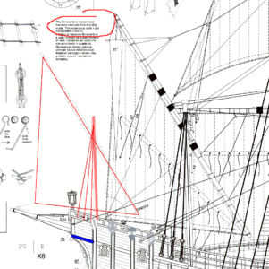
As I mentioned earlier in this thread, I would like to include a Bonaventure mast, sail and rigging, as often used on this style of ship. The plans mention it, and show the location, but has no other information or materials. The mast is highlighted in red:
1683664771423.png
There is enough sail material to make the sail of, provided I can make one that matches well enough, and I can assume rigging will be similar to that on the mizzenmast.

My question is about the channels and deadeyes: Would the channels be located about where I have shown in blue? I assume deadeyes in a similar arrangement to the mizzenmast would be used? Would the Bonaventure sail be a permanent arrangement on a given ship, or be mounted only under certain conditions, or what? Any additional information to help me decide to include it, and how, would be appreciated.
 
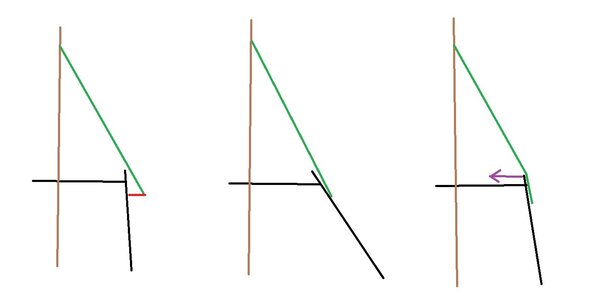
I am not sure, if a chanel for the much shorter Bonaventure mast would be geometrical possible
The shrouts are much shorter because of the reduced height -> the angle between the shrouds and the mast will be more shallow
=> the shrouds would contact the railing and would produce a kink in teh shrouds - like shown on this sketch on the right
or only with extreme wider chanels, but this would be also very complicated from technical stability point

Unbenanntaaa.jpg

So I guess the deadeyes wre installed inside the railing on the poop deck

Take a look at the Mary Rose

l2434_003.jpg

 
I am not sure, if a chanel for the much shorter Bonaventure mast would be geometrical possible
The shrouts are much shorter because of the reduced height -> the angle between the shrouds and the mast will be more shallow
=> the shrouds would contact the railing and would produce a kink in teh shrouds - like shown on this sketch on the right
or only with extreme wider chanels, but this would be also very complicated from technical stability point

View attachment 373715

So I guess the deadeyes wre installed inside the railing on the poop deck
Good point, Uwe, thanks for that. While the Mary Rose has more or less a continuous channel from the mainmast on back, the Bonaventure mast shrouds are not attached to it. So they may be attached to or inside the railing, as you say, or I wonder even to the poop deck, if there are deadeyes, as the deadeyes are not visible on the Mary Rose.

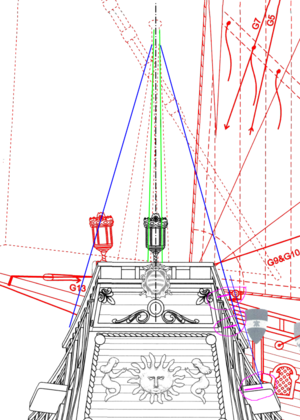
I made a layout by overlaying the side view (with the Bonaventure mast in green) and stern view, with shrouds in blue and channel width to shroud attachment in purple:
1683740886384.png
It does appear that there may be clearance to have the shrouds outside the rail one new channels, so that is still a possibility. It may well be that the shrouds did attach to, or inside of, the poop deck rails, though, as shown on the Mary Rose.

So there is some flexibility there, depending on what would be more historically accurate.
 
Looking at drawings and photos of models here and on the Net of the Mary Rose suggests that the shrouds, with deadeyes, was definitely attached to the decking (or more probably through decking bracing or cross embers) of the poop deck, with no outside channels. Whether this would be the same with the Ragusian Carrack, I don't know.

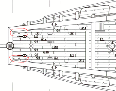
Actually, I just took a closer look at the drawings included with the kit. The plan of the poop deck shows rings (probably) that I believe are intended for the Bonaventure mast, circled in red below:
1683743941872.png
Unlike other attachment points, there is no coding of what rope attaches to them, and the spacing and longitudinal distance seems to match the Bonaventure shrouds. Plus, this is very similar to the Mary Rose drawings I've found.

It seems obvious, now, as do many other things once I finally understand them, but I'd really never noticed this before. Anyhow, always good to have a nice, informative discussion, right?
 
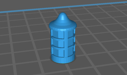
I had asked my son some time ago to make me some 3d printed small lanterns for use on this model. While I've only seen the large lanterns at the stern of ships, and sometimes on the platforms, I reasoned that it made sense to mount lanterns outside doors on the main deck at the forecastle as well as other doors. I found this STL file online and felt it would work for this purpose:
1684165533297.png
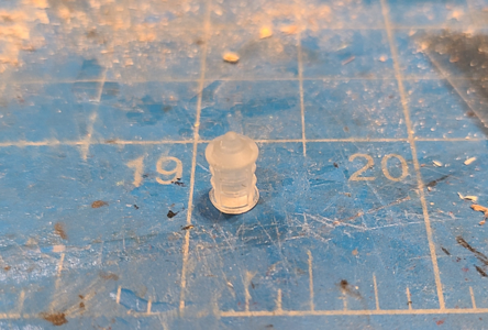
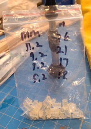
He made them in 4 sizes: 5.2, 7.2, 9.2 and 11.2mm high, scaling 12, 17, 21 and 26" high (they were supposed to be 6, 8, 10 and 12mm, but somehow ended up these dimensions).

I thought the largest I could use on this model was the 21" high scale version:
1684165642223.png
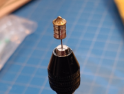
They are cast of clear resin, although came out a bit yellowish. I wanted to simulate some kind of candle or wick inside, so drilled a hole in the bottom of the lantern and put some red paint inside:
1684165711063.png
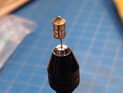
The drilled hole can also be used to mount the lantern. I've thought about mounting wire from the bottom, like this, or from the top, or possibly a small wood platform for mounting. I reasoned that only smaller lanterns would have hoops to carry around by hand.

After painting brass (still wet, and uneven, it appears) I have:
1684165808422.png
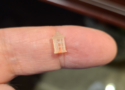
Like most of my work, it looks much better when viewed at actual size:
1684165935776.png
Here's a bag of lanterns, which I will use some much later in the build, when they won't get broken off:
1684166000362.png
 
Hello Signet, I really had to catch up a lot. I'm really impressed with your work and salute you, very neat work.
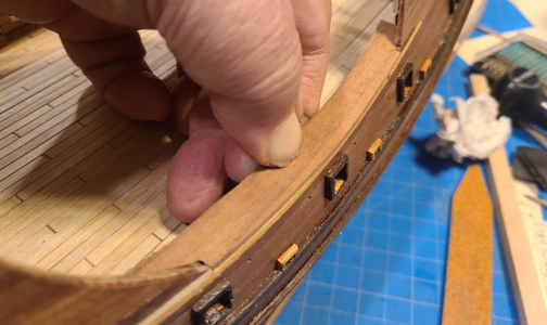
Unfortunately, the next photos show how very un-neat my work can be. I had major problems with the rubbing strakes on this model: most broke when trying to bend, did not want to stay where I wanted them when mounted to the hull (yeah, like they screwed up, not me), were damaged during application, didn't cover some defects I wanted them to, and created more defects that will somehow have to be covered.

Here, some inner detail and bracking has been added:
1684686812438.png
You will notice I took no close-up photos, as these expose all the defects. I did, however, purchase a multi-color putty repair kit which I hope to go back and correct or improve many of those areas later. For now, I'll leave most of them there, or I'd get nothing done other than correcting defects.

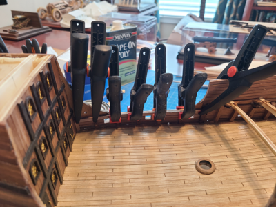
The tops of the rails were reinforced prior adding the tops:
1684687010622.png
Most building this kit have deviated from the described construction, usually making the rails thicker than intended, and I am no exception. The inner longitudinal rail reinforcement I made 0.6mm thick to keep this to a minimum, as the thickness cannot be seen:
1684687098735.png

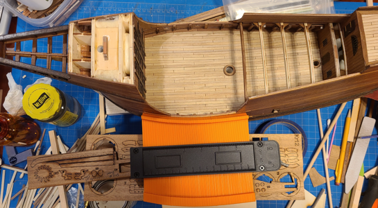
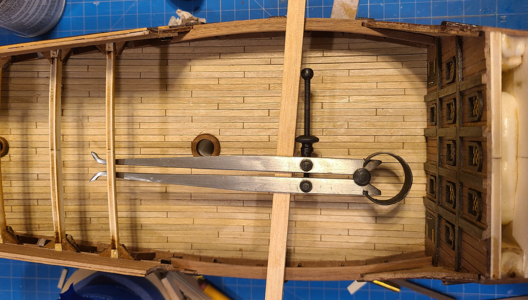
The top of the rails, of 2mm walnut, needs to match the contour or the sides of the ship, so I used a measuring gauge to determine the shape:
1684687167751.png

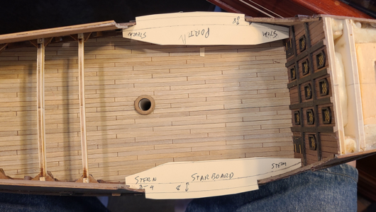
I then made paper templates to confirm the shapes:
1684687199291.png

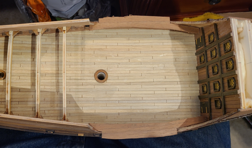
The walnut pieces were cut, and fit to the outer and inner edges:
1684687239395.png

Checking the fit of the rail top with the side of the hull:
1684687349108.png
Many have built this kit with the top of the rail above and overhanging the rubbing strake which then mounted below it. The kit, however, shows the strake blending into and forming part of the rail top, and that is what I am doing. I thought the fit above would end up seamless, but unfortunately it did not.

A final fit of the top rails before being glued in place:
1684687480465.png
The top rails are now glued in place:
1684687538849.png

I then glued and nailed the rubbing strake at top rail level. This was difficult for me to do, the strakes broke, never went properly in place, left gaps between them and the hull and rail, and in general this was a horrible experience. Some of this stuff I am just no good at. No photos were taken during this process. Oh, gee, I forgot!
images

Among other problems that occurred during the strake install is that some of the nails broke loose planking and ribs below the quarterdeck:
1684688247746.png
I thought it was just tears, at the time, but it appears that the photo is blurry too. Use your imagination.

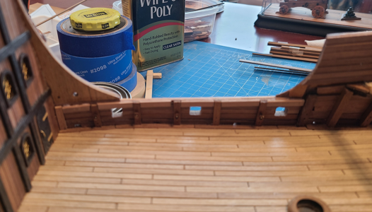
I didn't make the curved transitions between the main deck and higher decks like the instructions called for, and others did in their builds. I felt that these large, unplanked areas didn't feel right. They couldn't be made in one piece, and felt they should be planked, and if they were, felt they should be more a part of the ship. I had already planked them on the outside, so now planked them inside:
1684688474195.png
Likewise, I wanted rail portions on the curved sections, but knew from experience I couldn't bend 2mm pieces that way. So I used 3 pieces of 0.6mm thick material glued together, which bent easily. I'll finish them later and blend them into other structures better.

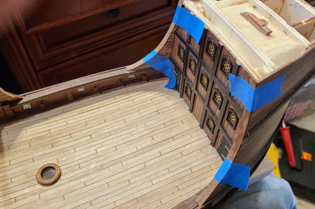
Final pictures after the curved strakes were installed and some other details. I suggest you stand at least 20 feet away from your computer when looking at these photos; it looks pretty good from there.
1684688645117.png
1684688667221.png
1684688690563.png
1684688713308.png
I keep telling myself that when it's done, you won't focus on the relatively small problems, but on the whole. I hope that's true. BTW, /most/ of the holes you see in the planking are for locating inner and other futtocks and bracing, and are supposed to be there. Some are not, and will be filled later.
 
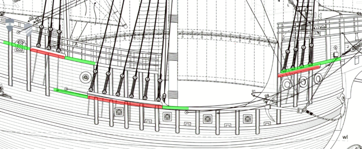
I have a question concerning the Channels (for shrouds) and the Wales which are near, or at, the channels, on this ship and in general. The instructions clearly (but not obviously) show the channels for the foremast BELOW the wales, but the channels for the mainmast and mizzenmast ON the channels:
1684722695440.png
(Wales shown in green, channels where they attach to the hull in red).

So for the foremast, it would look like this (left below):
1684722767291.png 1684722917072.png
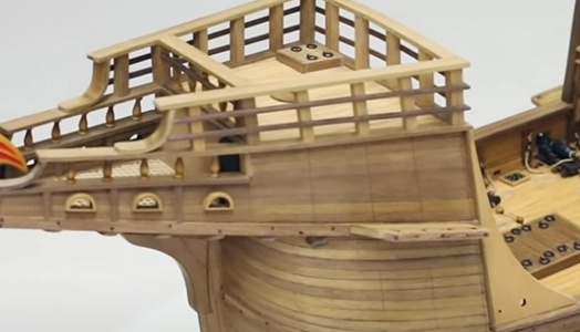
To the right above is Olha's model, where she has all channels ON the wales (no comparisons in quality, please - I see them too).

Is it normal to have channels ON the wales, or adjacent to them? I've show the channel for the mainmast below, on and above in these photos:
1684723129884.png 1684723144438.png
1684723174725.png
In any event, the mainmast channels need to be curved to match the wales, but I'm trying to figure out what is more appropriate or correct, and what looks best. Any comments, suggestions, etc. would be appreciated.
 
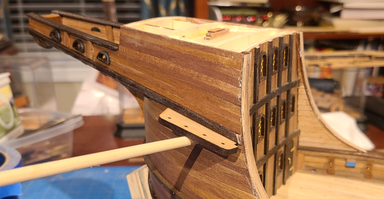
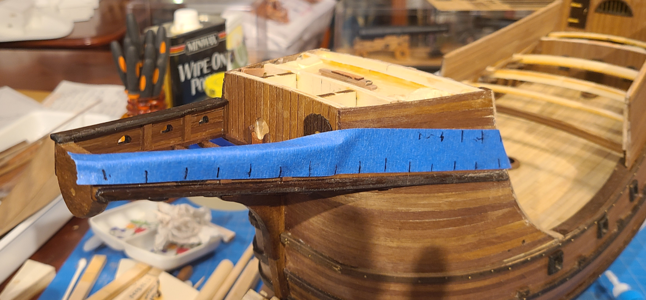
Thought I'd do some work on the rails near the bowsprit next. I wanted to add nails to the raised strip extending from the forecastle, and to help spacing, used marked tape to locate them:
1685323650319.png

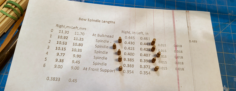
I purchased turned spindles for this area, as I have no lathe and knew the consistency of anything I could make would be poor. As their length varies, I took measurements at the forecastle and stem, and so used a spreadsheet to calculate the correct length for each one, to maintain the taper. I then sanded them by hand to the right dimensions:
1685323803412.png
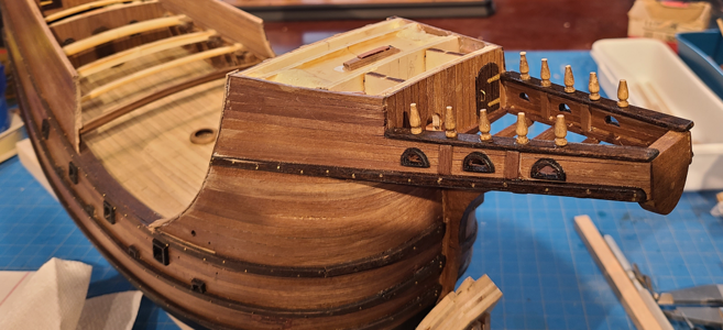
After mounting, they look like this:
1685323936376.png
Not quite correct profiles, but again, better than I could to by hand. The nails added above can also be seen.

Not quite sure how to proceed from there, I switched gears to the opposite end of the ship.

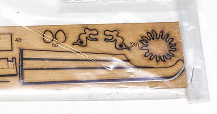
The rudder in the kit comes in 4 pieces:
1685324032524.png
The expected 3 pieces are there, but so also is an extremely narrow strip at the bottom, which the plans show attached to the bottom of the 3 pieces. With its grain direction and fragility, no way was that piece going to survive, so I decided to make a strip to replace it of 1.5mm strip.

What confused me a bit with the way the rudder was cut is that there are two very thin pieces, about 0.5mm wide, /between/ the 3 rudder pieces. I discarded them, considering them unnecessary, but it is confusing to me why the builder wouldn't just have a single cut separating each of the 3 pieces, instead of the two cuts making the thin scrap pieces: it would have required 2 less laser cuts, and insured that the pieces perfectly mated up (which they did just fine anyhow). Surely they weren't intended to be included, to accentuate the 3 pieces of the rudder?

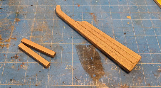
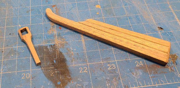
Once assembled, the 3 pieces of the rudder look like this:
1685324356287.png
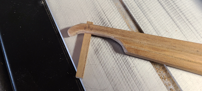
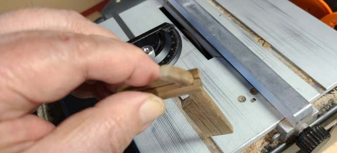
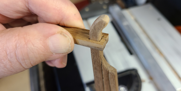
The 1.5mm strip is shown at the bottom. I wanted to emphasize the 3 pieces of the rudder (otherwise, just make it in 1 piece, right?), so beveled the pieces to highlight this. Perhaps I overdid it, but I still think it looks okay. The 2 pieces at the left were cut to make the rudder tiller; unlike Olha, who cut hers of one piece and drilled and filed the square hole, I could cut mine with a saw in this way:
1685324491995.png
fitting each half to the approximate position and checking the depth by assembling the two:
1685324534857.png
until I got a good fit:
1685324571238.png
Yes, I know the tiller is on backwards. I was testing you! :cool:

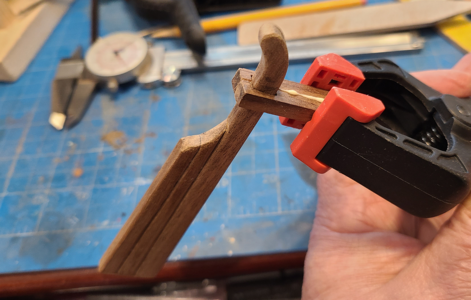
I glued the two tiller pieces together, first while mounted to the rudder to insure a good fit:
1685324642844.png
then when removed, to clamp it correctly.

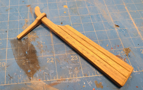
My rudder profile at the top deviated somewhat from the plans (the top had broken off and I added a new piece to it), and I had to go back and modify it to be sure I could remove the tiller prior to assembly. It has to slide over the top of the rudder, as well as down and up in that area to easily raise the rudder to mount into position over the pins. The finished combination:
1685324770107.png
I made the tiller longer than necessary, so I could trim it during assembly to the right length, making it enter the stern as far as possible, so as not to see the end of it.

And with tiller assembled to rudder:
1685324843311.png
and finally, held in place against the stern to check for fit:
1685324890752.png
Rather than cut the tiller to fit, I instead drilled a hole in the next-to-last bulkhead (#14) for it to go through, helping hold it in place and further hiding its end.

That's it for now. Hope everyone Stateside has a great Memorial Day. Don't eat too many burgers and hot dogs!
 
Last edited:
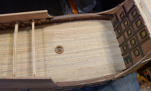
Thought I'd do some work on the rails near the bowsprit next. I wanted to add nails to the raised strip extending from the forecastle, and to help spacing, used marked tape to locate them:
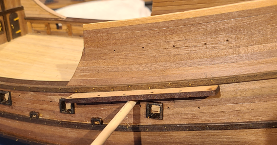
View attachment 376723

I purchased turned spindles for this area, as I have no lathe and knew the consistency of anything I could make would be poor. As their length varies, I took measurements at the forecastle and stem, and so used a spreadsheet to calculate the correct length for each one, to maintain the taper. I then sanded them by hand to the right dimensions:
View attachment 376724
After mounting, they look like this:
View attachment 376725
Not quite correct profiles, but again, better than I could to by hand. The nails added above can also be seen.

Not quite sure how to proceed from there, I switched gears to the opposite end of the ship.

The rudder in the kit comes in 4 pieces:
View attachment 376726
The expected 3 pieces are there, but so also is an extremely narrow strip at the bottom, which the plans show attached to the bottom of the 3 pieces. With its grain direction and fragility, no way was that piece going to survive, so I decided to make a strip to replace it of 1.5mm strip.

What confused me a bit with the way the rudder was cut is that there are two very thin pieces, about 0.5mm wide, /between/ the 3 rudder pieces. I discarded them, considering them unnecessary, but it is confusing to me why the builder wouldn't just have a single cut separating each of the 3 pieces, instead of the two cuts making the thin scrap pieces: it would have required 2 less laser cuts, and insured that the pieces perfectly mated up (which they did just fine anyhow). Surely they weren't intended to be included, to accentuate the 3 pieces of the rudder?

Once assembled, the 3 pieces of the rudder look like this:
View attachment 376727
The 1.5mm strip is shown at the bottom. I wanted to emphasize the 3 pieces of the rudder (otherwise, just make it in 1 piece, right?), so beveled the pieces to highlight this. Perhaps I overdid it, but I still think it looks okay. The 2 pieces at the left were cut to make the rudder tiller; unlike Olha, who cut hers of one piece and drilled and filed the square hole, I could cut mine with a saw in this way:
View attachment 376728
fitting each half to the approximate position and checking the depth by assembling the two:
View attachment 376729
until I got a good fit:
View attachment 376730
Yes, I know the tiller is on backwards. I was testing you! :cool:

I glued the two tiller pieces together, first while mounted to the rudder to insure a good fit:
View attachment 376731
then when removed, to clamp it correctly.

My rudder profile at the top deviated somewhat from the plans (the top had broken off and I added a new piece to it), and I had to go back and modify it to be sure I could remove the tiller prior to assembly. It has to slide over the top of the rudder, as well as down and up in that area to easily raise the rudder to mount into position over the pins. The finished combination:
View attachment 376732
I made the tiller longer than necessary, so I could trim it during assembly to the right length, making it enter the stern as far as possible, so as not to see the end of it.

And with tiller assembled to rudder:
View attachment 376733
and finally, held in place against the stern to check for fit:
View attachment 376734
Rather than cut the tiller to fit, I instead drilled a hole in the next-to-last bulkhead (#14) for it to go through, helping hold it in place and further hiding its end.

That's it for now. Hope everyone Stateside has a great Memorial Day. Don't eat too many burgers and hot dogs!
Good morning. I just caught up on your build and wow. This is fine modelling. I saw some large scale cannons in one photo behind your Carrack they look so good. Cheers Grant
 
I next added the middle portion of the rails for the stem of the vessel (Sorry, I'm not familiar with a lot of this termology):
1685479279743.png
I wanted to do this at this time to strengthen the spindles added previously.
1685479542340.png
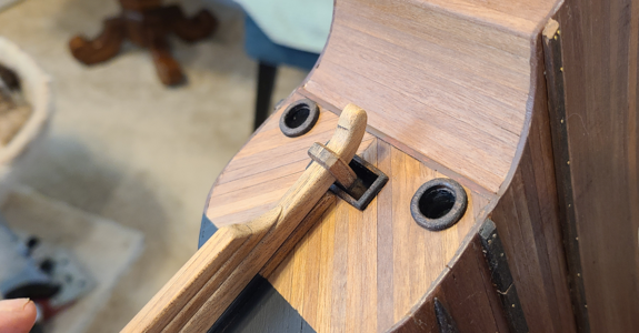
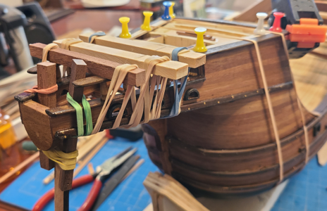
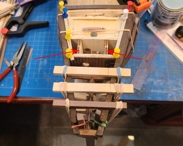
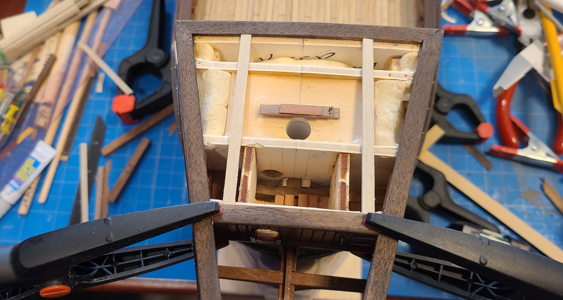
I will have to leave the planking off of this area until I install the catheads, as I want to round the inner end of them and have them insert into holes in the inner bulkheads, indicated by the arrows above.

Next, I placed the foremost member of the rails, which outlines the forecastle deck area. I cut the planks I'm using for the decking with a jig, so they are all the same length, then used two to set the spacing. This not only makes sure the members are parallel to each other, but that I will not have to trim or sand decking planks to insure a good fit.
1685479774515.png
1685479831255.png
1685480861757.png
A lot of errors and poor workmanship shows up here, unfortunately. Rather than fix each thing I can ASAP, I've decided instead to wait until most of a type of work is done, then go back and fix it all at once. I know it won't be perfect, but hopefully better than it is now.

Now to look at the catheads...
 
Back
Top