-

Win a Free Custom Engraved Brass Coin!!!
As a way to introduce our brass coins to the community, we will raffle off a free coin during the month of August. Follow link ABOVE for instructions for entering.
-

PRE-ORDER SHIPS IN SCALE TODAY!
The beloved Ships in Scale Magazine is back and charting a new course for 2026!
Discover new skills, new techniques, and new inspirations in every issue.
NOTE THAT OUR FIRST ISSUE WILL BE JAN/FEB 2026
- Home
- Forums
- Ships of Scale Build Logs
- Super Detailing Static Models / Other Genres
- Historical Trailways, Guns, Aircraft, and Cars
You are using an out of date browser. It may not display this or other websites correctly.
You should upgrade or use an alternative browser.
You should upgrade or use an alternative browser.
Model Airways Sopwith Camel 1/16 scale [COMPLETED BUILD]
Thank you Johan!Nice work on the radial!
Plug wires finished…similar to ship rigging, definitely tedious or fiddly, whichever you prefer! 
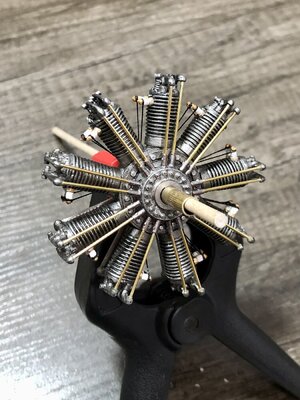
Then I noticed the intake runner flanges on the top (at the cylinder head) has no line or separation where they are bolted on. I wish I would have noticed while building the motor. I could have filed a groove prior to painting. At this point I chose to paint a black line, which never looks as realistic. But at least the joint is represented.
Before…
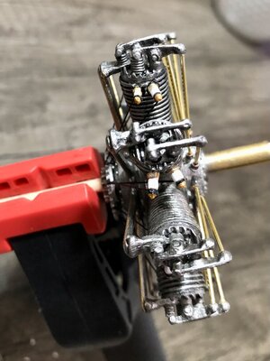
After…
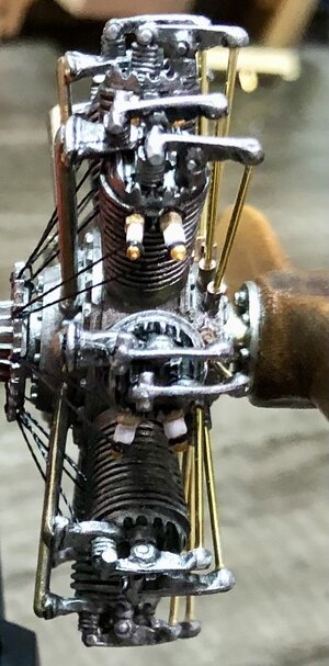
This completes step 1.
Time to prepare for building the upper wing.
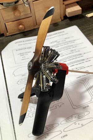
Pic of finished engine and propeller…


Then I noticed the intake runner flanges on the top (at the cylinder head) has no line or separation where they are bolted on. I wish I would have noticed while building the motor. I could have filed a groove prior to painting. At this point I chose to paint a black line, which never looks as realistic. But at least the joint is represented.
Before…

After…

This completes step 1.
Time to prepare for building the upper wing.
Pic of finished engine and propeller…


Last edited:
Model airplanes in balsa is where I got started in wood based modeling way back when as a teen. Gravitated to my first wooden ship model from there. Your build log here brings back many memories! Superb work! Thanks for posting.
Thank you! I actually started with plastic models as a teen. First was WW2 aircraft, then fighter jets. Then I started building wooden RC airplanes. My very first wooden plane was a control line with a gas motor!Model airplanes in balsa is where I got started in wood based modeling way back when as a teen. Gravitated to my first wooden ship model from there. Your build log here brings back many memories! Superb work! Thanks for posting.
Later I discovered wooden ship models. So now I have to get back to airplanes too. Not giving up ships, but I am due for a few airplane builds!
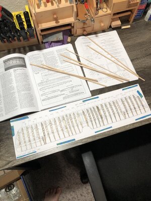
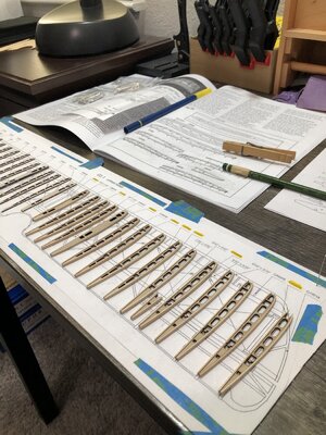
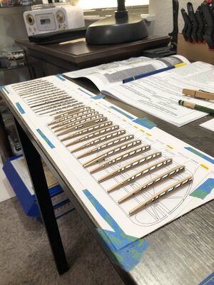
I started putting the cap strips on the wing ribs. First I sanded the char off the ribs, then cut the cap strips, soak them in water and then glue and clamp to the rib. After the glue dries, sand flush with the ends. Pretty much straight forward.
I have the first 3 done of 32. So I will be on this step for a while! But after that it will be time for the assembly to the spars, and will start to look like a wing. Something to look forward to!
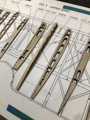
I have the first 3 done of 32. So I will be on this step for a while!

Last edited:
Thanks Lou! They tell you to make a jig, which is just a strip of the cap wood to sit the rib on. The thickness works out to be correct to center the cap strip. But I just made a mark where the edge of the rib should be on the inside of the cap strip, and used it as a visual guide.Looking good Dean, do they give you a jig to help center those cap strips or do you have to eyeball them?
Kurt Konrath
Kurt Konrath
Last time I built a wood kit with tissue surface was old P-38 back in late 70's.
Never got finished as I joined USAF and went to work on real aircraft, and the kit got lost at my folks place over the years.
Never got finished as I joined USAF and went to work on real aircraft, and the kit got lost at my folks place over the years.
The P-38 is a very cool airplane!Last time I built a wood kit with tissue surface was old P-38 back in late 70's.
Never got finished as I joined USAF and went to work on real aircraft, and the kit got lost at my folks place over the years.
You mean the struts? If so, I haven’t looked at them yet. If they are all metal, then I will make them wood.Jig?? We don’t need no stinkin jig!!are you going to use those metal compression bars in the kit? I’ve seen a couple of builds on britmodeler and elsewhere that cut the ends off and remake them in wood to be more realistic?….
They are a strut of sorts, not the interplane or inter wing struts though, they ran fore/aft in the wings, I think there are like 5 of them per wing half, they are made from metal in the kit but in reality they were wooden bars (or beams) with metal fittings on each end… you’ll see them pretty soon….
Ok, I understand, the turnbuckles attach to them for the inner wing support cables.They are a strut of sorts, not the interplane or inter wing struts though, they ran fore/aft in the wings, I think there are like 5 of them per wing half, they are made from metal in the kit but in reality they were wooden bars (or beams) with metal fittings on each end… you’ll see them pretty soon….
I thought you were referring to the large struts between the wings.
Heinrich, you knowing my family background, that is a great assumption!
I do love the way the Neiuport looks, and it was a great flying plane as far as speed and handling goes. Being part French from my fathers side does make me a little biased…lol. But as you know I am also part Italian from my fathers side, and they were also flown by the Italians in WW1. So yes it is my favorite.
As you remember I am also part German and Dutch on my mother’s side. And I am fond of the German airplanes as well. Which is why I want to build the Albatross D.VA kit too! Perhaps even the Fokker D1 triplane!
It is interesting to note, the Camel was a later development by Sopwith, and was a very capable airplane, probably one of the best of WW1 in terms of abilities. Sopwith had made a triplane prior to the Camel. The Germans decided they wanted a triplane, and Fokker developed one. What they didn’t realize, that Sopwith had already learned, is that even though the triplane was very good at aerobatics, being unstable (no dihedral in the any of the wings) and having a lot of lift…is that the design has a lot of drag and visibility is hampered! Seeing your enemy is very important! It was described as looking through blinds as they close. So as you look down, the visibility due to the wings is impaired and made landing them more difficult as well. However it didn’t seem to be much of a problem for Baron Von Richthofen.
And finally, the Camel was credited for the final fight of the Red Baron (Richthofen). Although it is still disputed as to whether it was ground fire or the Camel guns that killed Richthofen, the Ace of Aces
I cut 9 lengths of the provided black thread to install the plug wires. Each one going to 2 plugs.
I have a dowel and wood clamp as a makeshift motor stand. Actually works quite well.
View attachment 290436
Looking at the back of the motor, I realized the intake runners were void of bolts on both ends where the flanges are…sigh. So I decided to add some bolt heads (simulated) using an old technique where I add a drop of glue with a straight pin, to be painted afterwards.
Below I added to the upper flanges and started on the lower flange bolts…
View attachment 290437View attachment 290438
Then I paint with a drop of glue on a toothpick. I used bright silver to add contrast, to help make them stand out.
View attachment 290439
I add the paint with a toothpick dipped into the jar of paint, so it adds more height and is a controlled drop which remains round. At least that’s my logic verses using a brush for this task.
Then I decided to dry brush a little antique gold on the intake runners closest to the flanges on both ends. This is where the most heat would occur, and attempts to simulate heat cycling after much use. Once again a personal logic, but at the same time makes the model more interesting visually.
Before and after below…
View attachment 290440View attachment 290441
Now after being side tracked with adding additional detail (always happens!), I began adding the plug wires.
Here are the first 4, only 14 more to go!
View attachment 290442
And from behind…
View attachment 290443
The termination of the wires is not correct model wise, they should go to a pin that is in the holes on the gear, keeping them in front of the gear, the contact being the pin. But the model is simplified to make life easier, and they are just tied through the hole. If you want to go the extra mile, you could add the pins to the gear and tie the wires to them prior to installing the gear. It was too late to exercise this option for me! If I had it to do over, that is what I would do.
See you after I install the other 14 wires! What wonderful fun in your transition from moving air for a schooner sail to moving air for an wing airfoil!!! Beautiful precise work continues in both the shipyard and hanger. This is a reward to see. RichI cut 9 lengths of the provided black thread to install the plug wires. Each one going to 2 plugs.
I have a dowel and wood clamp as a makeshift motor stand. Actually works quite well.
View attachment 290436
Looking at the back of the motor, I realized the intake runners were void of bolts on both ends where the flanges are…sigh. So I decided to add some bolt heads (simulated) using an old technique where I add a drop of glue with a straight pin, to be painted afterwards.
Below I added to the upper flanges and started on the lower flange bolts…
View attachment 290437View attachment 290438
Then I paint with a drop of glue on a toothpick. I used bright silver to add contrast, to help make them stand out.
View attachment 290439
I add the paint with a toothpick dipped into the jar of paint, so it adds more height and is a controlled drop which remains round. At least that’s my logic verses using a brush for this task.
Then I decided to dry brush a little antique gold on the intake runners closest to the flanges on both ends. This is where the most heat would occur, and attempts to simulate heat cycling after much use. Once again a personal logic, but at the same time makes the model more interesting visually.
Before and after below…
View attachment 290440View attachment 290441
Now after being side tracked with adding additional detail (always happens!), I began adding the plug wires.
Here are the first 4, only 14 more to go!
View attachment 290442
And from behind…
View attachment 290443
The termination of the wires goes thru a hole, however I am certainly this should not have gear teeth but be a smooth diameter. I should have filed the teeth off prior to installation…sigh!
See you after I install the other 14 wires!
- Joined
- Apr 20, 2020
- Messages
- 6,234
- Points
- 738

Dear Dean
it's looks beautiful model and very impressive work
Thank you!Dear Dean
it's looks beautiful model and very impressive work


