MSW USS Constitution

A little update on my ship.
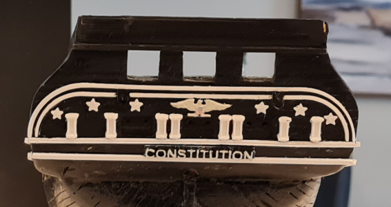
This is the best pics I can take with the phone that I have. I hope the pics do them justice.
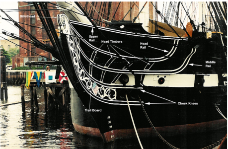
The next step is to work on the trailboards, the rails and the cheek knees, as per the third pic taken from R. Hunts practicum.


Screenshot 2025-02-13 103220.png

Screenshot 2025-02-13 103439.png

Screenshot 2025-02-13 103943.png
 
Last edited:
Hi Jack Sparrow -
Wow - some really nice accomplishments. It seems you have a large and healthy audience too. Me,,,, a little jealous. I rarely get any comments.
 
Hi Jack Sparrow -
Wow - some really nice accomplishments. It seems you have a large and healthy audience too. Me,,,, a little jealous. I rarely get any comments.
i just hope i can do the model justice. It is the most difficult thing I have ever built.
 
I agree, it is very difficult. The manual that came with it is not really a construction manual. You really have to focus on the plans. Of which I fail to do often and gets me into trouble. One of the main things is that there are two different sizes (widths) of planking they are using for the upper hull and bulwarks.
 
I agree, it is very difficult. The manual that came with it is not really a construction manual. You really have to focus on the plans. Of which I fail to do often and gets me into trouble. One of the main things is that there are two different sizes (widths) of planking they are using for the upper hull and bulwarks.
i agree 100%.
 
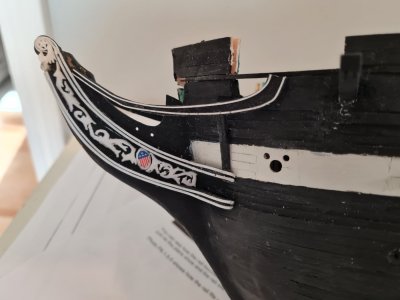
I spent the better part of 2 weeks trying to complete the trailboards. I imported a photo of them into freecad then traced the trailboard into an stl file ready for import into Cura Ultimaker, the software for generating Gcode that the 3d printer reads. I got a little stuck on the how to make the trim finish on the top of the trailboard. My solution was to wrap the mouldings around the star decoration sort of like how it is shown in the practicum but a little different.

I don't like that I see a seam, but I am not sure how to completely eliminate that. Maybe if I used a styrene glue it would melt the plastic and I can hide the seam better. If anyone has a better idea I am open to suggestions. Mind you this is a heavily magnified picture and from far, you don't really see that blasted seam.:)

pic.png
 
Last edited:
I spent the better part of 2 weeks trying to complete the trailboards. I imported a photo of them into freecad then traced the trailboard into an stl file ready for import into Cura Ultimaker, the software for generating Gcode that the 3d printer reads. I got a little stuck on the how to make the trim finish on the top of the trailboard. My solution was to wrap the mouldings around the star decoration sort of like how it is shown in the practicum but a little different.

I don't like that I see a seam, but I am not sure how to completely eliminate that. Maybe if I used a styrene glue it would melt the plastic and I can hide the seam better. If anyone has a better idea I am open to suggestions. Mind you this is a heavily magnified picture and from far, you don't really see that blasted seam.:)

View attachment 503752
Since you don't really see the seam (these closeup photos really DO magnify the flaws!) I'd say leave it, unless you are sure that "fixing" it just won't make it worse!
Your results really ARE terrific!
 
I spent the better part of 2 weeks trying to complete the trailboards. I imported a photo of them into freecad then traced the trailboard into an stl file ready for import into Cura Ultimaker, the software for generating Gcode that the 3d printer reads. I got a little stuck on the how to make the trim finish on the top of the trailboard. My solution was to wrap the mouldings around the star decoration sort of like how it is shown in the practicum but a little different.

I don't like that I see a seam, but I am not sure how to completely eliminate that. Maybe if I used a styrene glue it would melt the plastic and I can hide the seam better. If anyone has a better idea I am open to suggestions. Mind you this is a heavily magnified picture and from far, you don't really see that blasted seam.:)

View attachment 503752
Looks great, Jack, but if the seam is going to nag at you then here are some suggestions. Either Vallejo plastic putty or Tamiya white putty would do the trick. The former is a liquid, the latter a tube paste, so it would depend on your own preference which would be easiest to work with. You can also make your own putty by dousing some small bits of styrene in extra thin cement and working that around to completey dissolve the plastic until you get the consistency you want. Alternatively, you could insert a small piece of sheet styrene into the gap, apply extra thin liquid cement, and after letting that completely harden file the sheet down to the profile of the trim.
 
Looks great, Jack, but if the seam is going to nag at you then here are some suggestions. Either Vallejo plastic putty or Tamiya white putty would do the trick. The former is a liquid, the latter a tube paste, so it would depend on your own preference which would be easiest to work with. You can also make your own putty by dousing some small bits of styrene in extra thin cement and working that around to completey dissolve the plastic until you get the consistency you want. Alternatively, you could insert a small piece of sheet styrene into the gap, apply extra thin liquid cement, and after letting that completely harden file the sheet down to the profile of the trim.
thank you. good ideas
 
I spent the better part of 2 weeks trying to complete the trailboards. I imported a photo of them into freecad then traced the trailboard into an stl file ready for import into Cura Ultimaker, the software for generating Gcode that the 3d printer reads. I got a little stuck on the how to make the trim finish on the top of the trailboard. My solution was to wrap the mouldings around the star decoration sort of like how it is shown in the practicum but a little different.

I don't like that I see a seam, but I am not sure how to completely eliminate that. Maybe if I used a styrene glue it would melt the plastic and I can hide the seam better. If anyone has a better idea I am open to suggestions. Mind you this is a heavily magnified picture and from far, you don't really see that blasted seam.:)

View attachment 503752
Good morning Jack. My 2 cents would be to leave it as it is.!Looks mighty fine. Cheers Grant
 
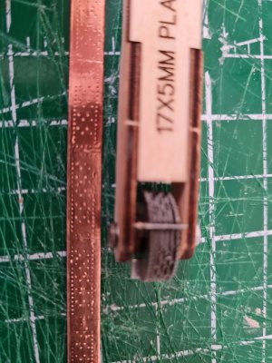
A small update. I am working on the stem of the ship, and realized that I ran out of wood, so I decided to start copper plating the hull. Pic1 shows my progress on the rails and pic 2 shows my new tool that I am using to make the copper plates. It seems to work well. I made a small jig for it and after a few tries with the jig, I realized I can get a better result by freehanding the tool.

pic1.jpg

pic2.jpg
 
A small update. I am working on the stem of the ship, and realized that I ran out of wood, so I decided to start copper plating the hull. Pic1 shows my progress on the rails and pic 2 shows my new tool that I am using to make the copper plates. It seems to work well. I made a small jig for it and after a few tries with the jig, I realized I can get a better result by freehanding the tool.

View attachment 508399

View attachment 508400

Interesting looking device Jack S. I purchased and used pre-stamped tape, as you know, but I reckon your “plate/nail indenter” is very efficient.
 
Interesting looking device Jack S. I purchased and used pre-stamped tape, as you know, but I reckon your “plate/nail indenter” is very efficient.
I have 3 rolls of copper tape not stamped so I figured I would put it to use by using that tool. I hope it won`t break on me. lol
So the process is you stamp the tape and then you cut the tape into plates. It is going to take a long time to get the amount that I need, so in order not to get bored I will make a bunch of plates, install them and make more plates when I run out.
It looks like the stamp is too small for the tape, but there is some overlap between the plates that I have to do so I should be ok.
 
It looks like the stamp is too small for the tape
If you look at the actual plates from USS Constitution, based on the large size and number of holes in your photo, it seems the wheel may actually be too large regarding the size and spacing of the wheel punch pins. Still, it is far better to have dimples rather than big bumps often seen.
Allan
Copper plate pattern tape versus Constitution.PNG
 
If you look at the actual plates from USS Constitution, based on the large size and number of holes in your photo, it seems the wheel may actually be too large regarding the size and spacing of the wheel punch pins. Still, it is far better to have dimples rather than big bumps often seen.
Allan
View attachment 508441
Thanks. I see what you mean.
There is not much out there which is to scale so I picked the smallest wheel I could.
 
Back
Top