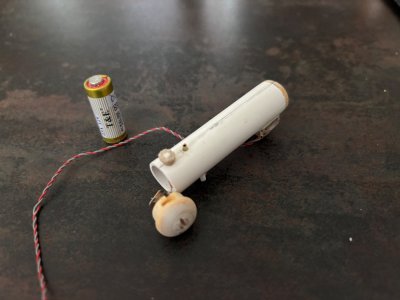
Mad scientist stuff...After preliminary assembly of the first two fuel tanks, which still need to have their end covers finished, it was time to address the first of two custom tanks. One tank has to hold a battery (I switched from AAA to 23A batteries for the higher voltage of the latter), while the other one will be equipped with a simple on/off switch.
Obviously, the plus- and minus points of the battery should ultimately be connected to the switch and the lights, so I ordered the required parts and upon receipt of these parts I started to fiddle around, based on the sketches I made.
The main body of the tank is made from a 14mm tube, thickness 1mm. The battery has a diameter of 10mm (and a length of 28mm), which means it nicely fits the tank. The aft cover of the tank is provided with the plus connection, which is located inside a 12mm tube, thickness 1mm, which holds the battery in position. The smaller tube is bonded to the aft cover. The aft cover has to be removable in order to be able to change the battery. The fwd cover houses the mass connection. Because the length of the battery is 28mm, a spacer is needed to fill the difference between battery and tank length. The fwd end of the tank body also has a feed through, which allows the wires to exit the tank and through the crossfeed lines to the next tank. Since the fuel system is provided with external cross feeds, it is rather convenient to use this to connect the battery to the switch.
While the aft tank cover has to be removable, the fwd cover is permanently attached. There is a good reason for that; the fwd tank attachment is through a clevis on the fwd tank cover. This prevents the fwd cover from being removable.
Since the aft cover is removable, slack in the plus-wire is needed. Because the diameter of the battery is smaller than the inner tube diameter, I have some room to store some slack wire.
Below in a picture what I tried to describe above, I hope this clarifies a lot of my rambling...
View attachment 481737
-

Win a Free Custom Engraved Brass Coin!!!
As a way to introduce our brass coins to the community, we will raffle off a free coin during the month of August. Follow link ABOVE for instructions for entering.
-

PRE-ORDER SHIPS IN SCALE TODAY!
The beloved Ships in Scale Magazine is back and charting a new course for 2026!
Discover new skills, new techniques, and new inspirations in every issue.
NOTE THAT OUR FIRST ISSUE WILL BE JAN/FEB 2026
- Home
- Forums
- Ships of Scale Build Logs
- Super Detailing Static Models / Other Genres
- Historical Trailways, Guns, Aircraft, and Cars
You are using an out of date browser. It may not display this or other websites correctly.
You should upgrade or use an alternative browser.
You should upgrade or use an alternative browser.
Simple and cleverThis sketch came into my mind Johan. Make a cardstock cut out of your first rounded end to use as a template for the rest. That way you have a good chance to achieve uniformity.
View attachment 481628
Johan has been doodling plenty while on the beach.Mad scientist stuff...
Clearly your plans are coming together Johan- nice.
Cheers Grant
- Joined
- Oct 1, 2023
- Messages
- 2,012
- Points
- 488

Didn't you build another model airways modelI am very much impressed with your design and build Johan. I shall have to try that one day. I have been using TurboCAD for the last 15 years and have a love/hate
relation with it.
Best regards
Ted
- Joined
- Sep 3, 2021
- Messages
- 5,197
- Points
- 738

Modeling is a bit on and off right now; some other things have taken priority. That doesn't mean no progress has been made.
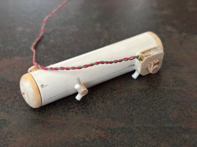
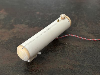
I have one tank more or less complete, with cross feeds, fuel pump, fuel vent and filler cap. It also happens to be the tank with the battery for the lights, requiring a removable tank cap.
Below a few pictures of the results, the fuel cap is still subject to evaluation; I'm not convinced of its geometry.
Top view looking fwd, with cap and battery removed. Filler cap and vent opening visible.

Bottom view looking fwd/up, fuel crossfeeds and fuel pump visible.

View looking aft/down. Fuel vent and filler cap visible.

I have one tank more or less complete, with cross feeds, fuel pump, fuel vent and filler cap. It also happens to be the tank with the battery for the lights, requiring a removable tank cap.
Below a few pictures of the results, the fuel cap is still subject to evaluation; I'm not convinced of its geometry.
Top view looking fwd, with cap and battery removed. Filler cap and vent opening visible.

Bottom view looking fwd/up, fuel crossfeeds and fuel pump visible.

View looking aft/down. Fuel vent and filler cap visible.

Looking good Johan! Some nice details available to you at this scale.
I can see your concept turning into a promising model.
Nice tiny details, Johan.Modeling is a bit on and off right now; some other things have taken priority. That doesn't mean no progress has been made.
I have one tank more or less complete, with cross feeds, fuel pump, fuel vent and filler cap. It also happens to be the tank with the battery for the lights, requiring a removable tank cap.
Below a few pictures of the results, the fuel cap is still subject to evaluation; I'm not convinced of its geometry.
Top view looking fwd, with cap and battery removed. Filler cap and vent opening visible.
View attachment 483369
Bottom view looking fwd/up, fuel crossfeeds and fuel pump visible.
View attachment 483368
View looking aft/down. Fuel vent and filler cap visible.
View attachment 483367
Regards, Peter
- Joined
- Oct 28, 2018
- Messages
- 760
- Points
- 403

Good job Johan,
I understand that it is quite a challenge.
The more beautiful when your model is completed, and then you forget all about it
.
Greetings
Henk
I understand that it is quite a challenge.
The more beautiful when your model is completed, and then you forget all about it
.
Greetings
Henk
Just catching up, I'm impressed by your thinking, sketching and engineering . That is going to be a fantastic model.
Jan
Jan
- Joined
- Sep 3, 2021
- Messages
- 5,197
- Points
- 738

Looking good Johan! Some nice details available to you at this scale.
I can see your concept turning into a promising model.
Nice tiny details, Johan.
Regards, Peter
Good job Johan,
I understand that it is quite a challenge.
The more beautiful when your model is completed, and then you forget all about it
.
Greetings
Henk
Just catching up, I'm impressed by your thinking, sketching and engineering . That is going to be a fantastic model.
Jan
Thanks for visiting and your words of encouragement.
For some odd reason this build cost me more time to plan and build. All too frequently I have to take a step back and reconsider my plans.
- Joined
- Sep 3, 2021
- Messages
- 5,197
- Points
- 738

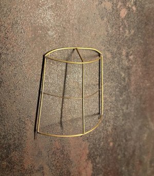
While I was trying to complete another tank, I discovered that the crossfeed manifold was too large. Being fed up with this situation, I changed focus and started on the canopy frame. Like I did on the 1:48 canopy frame, I used brass wire and tube for the frame and solder and CA to connect the parts. Working on the frame in 1:24 does make a difference, though it's still very laborious and finicky, but I now have the windshield frame and first part of the top frame complete.
While drilling some 0,5mm (0,020") holes, I broke quite a few drills...
Below a picture of the frame, I admit I'm quite pleased with the results of an evening's work:

While drilling some 0,5mm (0,020") holes, I broke quite a few drills...

Below a picture of the frame, I admit I'm quite pleased with the results of an evening's work:

The joinery on your metal work does indeed look pleasing to the eye.
Looks promising! Not so easy to solder I'm guessing...
- Joined
- Sep 3, 2021
- Messages
- 5,197
- Points
- 738

The joinery on your metal work does indeed look pleasing to the eye.
The joints are a freaking nightmare. Still, a bucket full of patience is quite helpful.Looks promising! Not so easy to solder I'm guessing...
Looking good, Johan. The transparent canopy will give it strength.While I was trying to complete another tank, I discovered that the crossfeed manifold was too large. Being fed up with this situation, I changed focus and started on the canopy frame. Like I did on the 1:48 canopy frame, I used brass wire and tube for the frame and solder and CA to connect the parts. Working on the frame in 1:24 does make a difference, though it's still very laborious and finicky, but I now have the windshield frame and first part of the top frame complete.
While drilling some 0,5mm (0,020") holes, I broke quite a few drills...
Below a picture of the frame, I admit I'm quite pleased with the results of an evening's work:
View attachment 483893
Regards, Peter
- Joined
- Sep 3, 2021
- Messages
- 5,197
- Points
- 738

Hey Peter,Looking good, Johan. The transparent canopy will give it strength.
Regards, Peter
Luckily the curved canopy parts already give some rigidity to the assembly. It's still rather fragile though; I'll be glad indeed when the transparancies are attached.
Regards, Johan
Good afternoon Johan. I think Daniel and Paul understated this soldering. It is so clean-nice. It must be a Dutch characteristic to work with tiny, fragile details so well. You and Peter come to mind. Cheers Grant
Say Johan, have you tried using soldering paste on the joints, it's a combination of powered solder mixed with flux. Squirt a dab on the cleaned joint, heat it up and it just flows into place.
- Joined
- Oct 1, 2023
- Messages
- 2,012
- Points
- 488

Maybe Johan's next project will be a scratch built watch

