• LUCZORAMA SHIPWRECK SCAVENGER HUNT GIVEAWAY. 4 Weeks of Fun • 1 Legendary Prize ((OcCre’s Fram Ship)) • Global Crew Welcome!
    **VIEW THREAD HERE**

NHI Kolibri N-3, scale 1:48, scratch build

Joined
Sep 3, 2021
Messages
5,021
Points
738

As I mentioned a while ago, I intend to build a model of the NHI (Nederlandse Helicopter Industrie) H-3 in scale 1:48.
A rather comprehensive description of the project can be found here: https://www.heli-archive.ch/en/helicopters/in-depth-articles/nhi-h-3-kolibrie. It's an exceptionally well written article with information on all aspects of this project.

During the mid fifties my father was involved in the design of this Dutch helicopter, the main reason why I selected to build this rotorcraft. It was a very small helicopter, driven by two rotor tip-mounted ramjets; the noise coming from these engines was er splitting and as a child I was scared s....less, just by the sound of it. As a result, I was never to be found anywhere near the thrice darned thing.

Below a picture of the Kolibri H-1; my father is the man in center front, if I remember correctly, he was responsible for the rotor head design.
This picture was taken about a half year before my birth:
9f54cacd-0911-42a3-8eb4-336b292e6251.jpeg


A picture of the Kolibri H-3 model:
IMG_0524.jpeg

Unfortunately, detailed information, ie drawings, are severely lacking, sofar I uncovered a few pics from an old brochure, with some dimensions and I was able to locate a sideview of the H-3 model.
Initially I thought to scale the avialble pictures to1:48 and start the build using these, but I realized rather quickly that that would be a rather bad idea; especially the rotorhead design need to be more detailed than what's shown on the drawings.
This led to the decision to define the helicopter in 3D-models. This meant I needed a 3D software package and, since I own a ten year old Macbook, it was to be compatible with the old MacOS Catalina. That ruled out the use of Fusion 360, but luckily FreeCad still runs on the old OS...
So I now find myself deep diving into mastering a new and unfamiliar Cad-program, while simultaneously trying to obtain a more or less correct product definition.

An isometric view of the H-3 model:
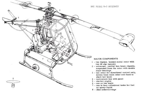
IMG_0504.jpeg

A 3 view sketch of the H-3 model, with some main dimensions:
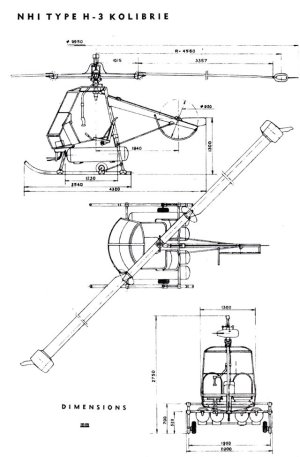
IMG_0533.jpeg

A side view drawing, again of the H-3 model
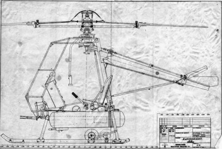
NHI Kolibri 5.jpeg
(None of these picture are mine...)

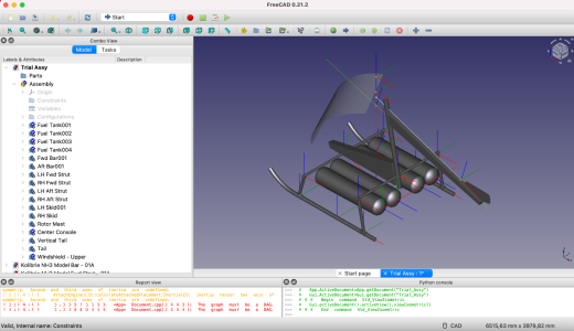
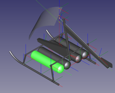
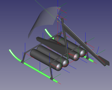
After some hours spend struggling with FreeCad, I now have a basic assembly model with various axis systems and components like the undercarriage, the fuel tanks and the rotor mast.
As can be clearly seen, a lot of work is still required before I have anything useful...

First attempt at the assembly model:
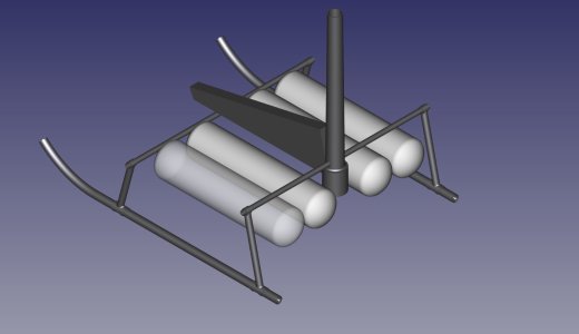
Frame Kolibrie.jpeg

Second attempt, using multiple axis systems for the main components and system lines starting to appear for the tail (green) and the tail rotor drive shaft (white). More definition to follow:
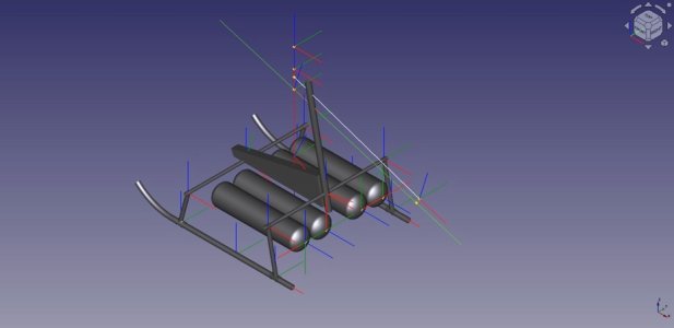
Foto 30-08-2024 om 08.59.jpeg
 
Last edited:
As I mentioned a while ago, I intend to build a model of the NHI (Nederlandse Helicopter Industrie) H-3 in scale 1:48.
A rather comprehensive description of the project can be found here: https://www.heli-archive.ch/en/helicopters/in-depth-articles/nhi-h-3-kolibrie. It's an exceptionally well written article with information on all aspects of this project.

During the mid fifties my father was involved in the design of this Dutch helicopter, the main reason why I selected to build this rotorcraft. It was a very small helicopter, driven by two rotor tip-mounted ramjets; the noise coming from these engines was er splitting and as a child I was scared s....less, just by the sound of it. As a result, I was never to be found anywhere near the thrice darned thing.

Below a picture of the Kolibri H-1; my father is the man in center front, if I remember correctly, he was responsible for the rotor head design.
This picture was taken about a half year before my birth:
9f54cacd-0911-42a3-8eb4-336b292e6251.jpeg


A picture of the Kolibri H-3 model:
View attachment 468327

Unfortunately, detailed information, ie drawings, are severely lacking, sofar I uncovered a few pics from an old brochure, with some dimensions and I was able to locate a sideview of the H-3 model.
Initially I thought to scale the avialble pictures to1:48 and start the build using these, but I realized rather quickly that that would be a rather bad idea; especially the rotorhead design need to be more detailed than what's shown on the drawings.
This led to the decision to define the helicopter in 3D-models. This meant I needed a 3D software package and, since I own a ten year old Macbook, it was to be compatible with the old MacOS Catalina. That ruled out the use of Fusion 360, but luckily FreeCad still runs on the old OS...
So I now find myself deep diving into mastering a new and unfamiliar Cad-program, while simultaneously trying to obtain a more or less correct product definition.

An isometric view of the H-3 model:
View attachment 468329

A 3 view sketch of the H-3 model, with some main dimensions:
View attachment 468330

A side view drawing, again of the H-3 model
View attachment 468331
(None of these picture are mine...)

After some hours spend struggling with FreeCad, I now have a basic assembly model with various axis systems and components like the undercarriage, the fuel tanks and the rotor mast.
As can be clearly seen, a lot of work is still required before I have anything useful...

First attempt at the assembly model:
View attachment 468332

Second attempt, using multiple axis systems for the main components and system lines starting to appear for the tail (green) and the tail rotor drive shaft (white). More definition to follow:
View attachment 468333
Today I was privileged to see your Fokker ‘Spin’ in real life and you research for the ‘Kolibri’. I have placed my chair to watch this build, Johan. Interesting CAD drawing.
Regards, Peter
 
Time for some update on my current build, the nimble Kolibri.
The 3D definition is still ongoing, which is coupled to a steep learning curve. Although having used Dassault Systems CATIA versions 3, 4 and 5, starting to use another 3D-definition software requires relearning the methods and getting acquainted with the quirks of the software; the main building blocks are the same, but getting to the required results may be an entirely different route towards the goal.
I added the tail to the model, as well as the main part of the windshield, the 3D model starts to resemble a Kolibri.
Still trying to do reverse engineering on the rotor head, which has become a major headache. I am trying to understand the working of both the collective and the cyclic, unfortunately the information I have seems to be somewhat conflicting in some regards. Once I wrap my mind around it, I will elaborate further.
In terms of information, I contacted the Aviodrome in the Netherlands and they possibly have some more information than I have accumulated. I hope to be able to extend my personal archive with quite some useful information.

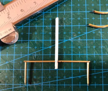
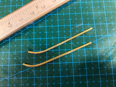
I also started making some parts, more as a trial than anything else. I am trying to get a feel for the scale and i also want to see whether or not my selection of materials and dimensions results in a visually pleasing model. Currently manufactured are the aft struts, aft bar and main mast. Also the two skids were made, as well as one of the fuel tanks.

1. The current 3D model, with tail and main windshield:
Schermafbeelding 2024-09-08 om 12.18.01.png

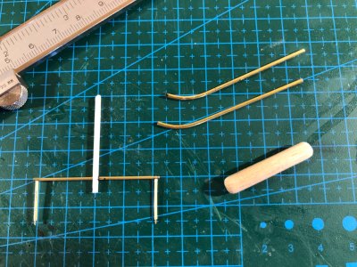
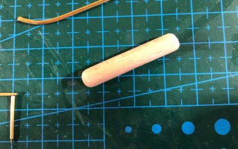
2. Overview of parts made to date:
IMG_2500.jpeg

3a. The first fuel tank:
IMG_2503.jpeg
3b: In 3D:
Schermafbeelding 2024-09-08 om 12.19.03.png

4a: The main mast with the aft bar and struts:
IMG_2502.jpeg
4b. In 3D:
Schermafbeelding 2024-09-08 om 12.19.30.png

5a. The tow skids:
IMG_2501.jpeg
5b. And again their counterparts in 3D:
Schermafbeelding 2024-09-08 om 12.19.54.png
 
Last edited:
Time for some update on my current build, the nimble Kolibri.
The 3D definition is still ongoing, which is coupled to a steep learning curve. Although having used Dassault Systems CATIA versions 3, 4 and 5, starting to use another 3D-definition software requires relearning the methods and getting acquainted with the quirks of the software; the main building blocks are the same, but getting to the required results may be an entirely different route towards the goal.
I added the tail to the model, as well as the main part of the windshield, the 3D model starts to resemble a Kolibri.
Still trying to do reverse engineering on the rotor head, which has become a major headache. I am trying to understand the working of both the collective and the cyclic, unfortunately the information I have seems to be somewhat conflicting in some regards. Once I wrap my mind around it, I will elaborate further.
In terms of information, I contacted the Aviodrome in the Netherlands and they possibly have some more information than I have accumulated. I hope to be able to extend my personal archive with quite some useful information.

I also started making some parts, more as a trial than anything else. I am trying to get a feel for the scale and i also want to see whether or not my selection of materials and dimensions results in a visually pleasing model. Currently manufactured are the aft struts, aft bar and main mast. Also the two skids were made, as well as one of the fuel tanks.

1. The current 3D model, with tail and main windshield:
View attachment 470018

2. Overview of parts made to date:
View attachment 470025

3a. The first fuel tank:
View attachment 470022
3b: In 3D:
View attachment 470019

4a: The main mast with the aft bar and struts:
View attachment 470023
4b. In 3D:
View attachment 470021

5a. The tow skids:
View attachment 470024
5b. And again their counterparts in 3D:
View attachment 470020
I see some very nice steps, Johan. And good to hear that the Aviodrome perhaps some extra information and documentation.
Regards, Peter
 
I see some very nice steps, Johan. And good to hear that the Aviodrome perhaps some extra information and documentation.
Regards, Peter
I was pleasantly surprised with this news. Initially it was said that no information was available anymore. At least this warrants a visit to the Aviodrome.

I’ll have to leave the graphic modeling to people smarter than me though.
That's exactly what I tried to do while still at work... ROTF

I am very much impressed with your design and build Johan. I shall have to try that one day. I have been using TurboCAD for the last 15 years and have a love/hate
relation with it.
It's a fun thing to do, the main drawback being that I need a lot of time thinking things trough, but that's due to my lack of grey matter (inside my head, not on top of it, although it's receding at a fast pace...)
Unfortunately I don't have any experience with TurboCad, but having (some) experience with Cadam (that's really old), Autocad, Cadds5 and Catia I learned the hard way there's no "easy" or "simple" in 3D modelling. It's always associated with a steep learning curve and way too many options and menus to choose from.
 
Hello y'all,

Making progress, but not physical.
I do have an appointment with the Aviodrome archives on October 9th, first opportunity. The material is from a private archive from one of my father's colleagues. It was handed over to the Aviodrome a few years ago.
Furthermore, I'm still working on the 3D-model. I now have the transparancies modeled, next step is the framework for the transparancies.

It doesn't look like it, but those transparancies gave me some formidable headaches.
Schermafbeelding 2024-09-12 om 21.15.42.png

It now starts resembling a Kolibrie:
Schermafbeelding 2024-09-12 om 21.13.47.png

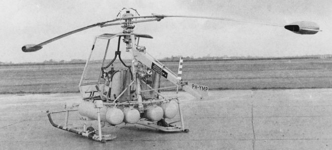
For reference, a picture of the real thing:
IMG_0003.jpeg
 
Last edited:
Hello y'all,

Making progress, but not physical.
I do have an appointment with the Aviodrome archives on October 9th, first opportunity. The material is from a private archive from one of my father's colleagues. It was handed over to the Aviodrome a few years ago.
Furthermore, I'm still working on the 3D-model. I now have the transparancies modeled, next step is the framework for the transparancies.

It doesn't look like it, but those transparancies gave me some formidable headaches.
View attachment 470803

It now starts resembling a Kolibrie:
View attachment 470804

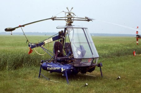
For reference, a picture of the real thing:
View attachment 470806
Yes sir, curved surfaces lofted into 3D space not on normal xyz headings is nightmarish. Looks good Johan.
 
Hello y'all,

Making progress, but not physical.
I do have an appointment with the Aviodrome archives on October 9th, first opportunity. The material is from a private archive from one of my father's colleagues. It was handed over to the Aviodrome a few years ago.
Furthermore, I'm still working on the 3D-model. I now have the transparancies modeled, next step is the framework for the transparancies.

It doesn't look like it, but those transparancies gave me some formidable headaches.
View attachment 470803

It now starts resembling a Kolibrie:
View attachment 470804

For reference, a picture of the real thing:
View attachment 470806
That complex part look good, Johan. And a small step is still a step forwards. Hopefully gives your visit to the Aviodrome you a lot of information. And a better contact than I hoped to have with the Scheepvaartmuseum. Because of postponing it is now silence. It seems arrogance towards 'amateur model builders'.
Regards, Peter
 
Yes sir, curved surfaces lofted into 3D space not on normal xyz headings is nightmarish. Looks good Johan.
Thanks Dan,
To be honest, in the course of this process I have created about a zillion local axis systems and sketches. Curves in 3D is something I still have to discover in FreeCad.
Johan

That complex part look good, Johan. And a small step is still a step forwards. Hopefully gives your visit to the Aviodrome you a lot of information. And a better contact than I hoped to have with the Scheepvaartmuseum. Because of postponing it is now silence. It seems arrogance towards 'amateur model builders'.
Regards, Peter
Thanks Peter,
The canopy consists of six different parts in the 3D-model, lower and upper windshield, the fwd top canopy, the center top canopy and two LH and RH top canopy parts, next to the center canopy. The frame work definition is next but possibly a redo of the windshields first; they are probably sitting too high with respect to the floor. Hopefully that can be resolved ved by positioning one of the axis systems. Fingers X-ed.

So far my questions have been answered swiftly and correctly by my contact at the Aviodrome. After initially stating there wasn't any information of the Kolibrie, he later informed me there actually still was some and re-directed me to another contact. I have high hopes.
Johan
 
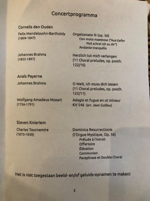
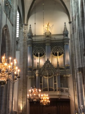
This afternoon something entirely different: Ellen and I are visiting one of the weekly concerts in the Domkerk of Utrecht .
Today the organ will be played by three students from the Rotterdam conservatory.

This afternoon's program :
IMG_2517.jpeg

And the ever imposing organ:
IMG_2516.jpeg
 
Last days saw two separate actions:
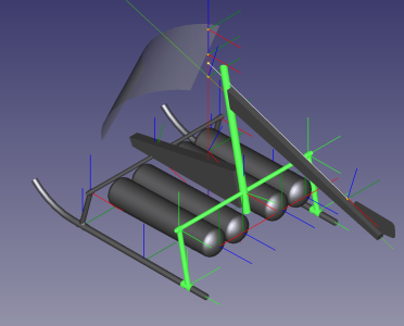
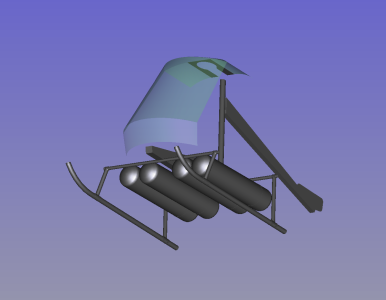
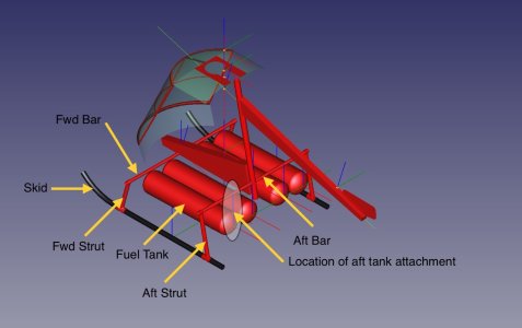
1. Trying to sort out the aft attachment of the fuel tanks. The information I have is seriously lacking detail. I thought I would do be able to determine the details by reverse engineering, but alas, that's not to be, I definitely need more and better details. This holds up the entire project; the tanks need to be attached to the fwd an aft bars, before installing the struts to the skids. See picture below:

ISO-01-01.jpeg

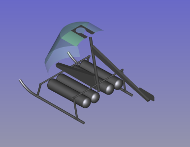
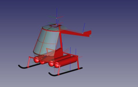
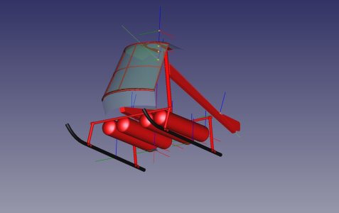
2. Work continues on the 3D definition, with focus on the framework for the transparencies. As already shown in the picture above, I started coloring the parts to match the intended colorscheme, which in turn is matching with the H-3 as displayed in the Avidrome:
ISO-02-01.jpegISO-03-01.jpeg

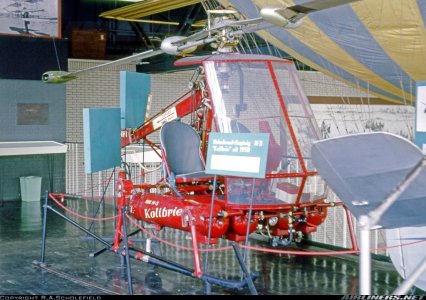
The H-3, as on display in Lelystad (source Airlines.net)
IMG_0783.jpeg
 
Last edited:
Last days saw two separate actions:
1. Trying to sort out the aft attachment of the fuel tanks. The information I have is seriously lacking detail. I thought I would do be able to determine the details by reverse engineering, but alas, that's not to be, I definitely need more and better details. This holds up the entire project; the tanks need to be attached to the fwd an aft bars, before installing the struts to the skids. See picture below:

View attachment 471239

2. Work continues on the 3D definition, with focus on the framework for the transparencies. As already shown in the picture above, I started coloring the parts to match the intended colorscheme, which in turn is matching with the H-3 as displayed in the Avidrome:
View attachment 471240View attachment 471241

The H-3, as on display in Lelystad (source Airlines.net)
View attachment 471242
That looks great! It takes ‘some’ time, but the satisfaction will be there, Johan. It's nice that it also shows the window transparently.
Regards, Peter
 
That looks great! It takes ‘some’ time, but the satisfaction will be there, Johan. It's nice that it also shows the window transparently.
Regards, Peter
Indeed, Peter, it takes "some" time, but currently I'm not in a building frenzy mode (yet). The fuel tank attachment issue was already addressed in my previous post, but the next or maybe parallel topic is to tackle the rotor head workings, I need to understand how that works. I'm half way there, I think; I more or less understand how the collective works (and also the adjustment of the tail rotor). What's left is the cyclic.

Admittedly, working on the 3D definition is very satisfying, especially when one discoveres more and more options, transparency being one of them. What is a bit concerning though is that one has to find a working method to define all parts, subassemblies and assemblies. There are various methods possible, all with their own pros and cons. The trap to avoid now is to change the method too much during the process...
 
Last edited:
Back
Top