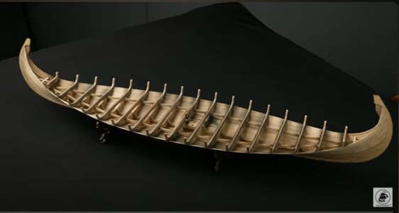
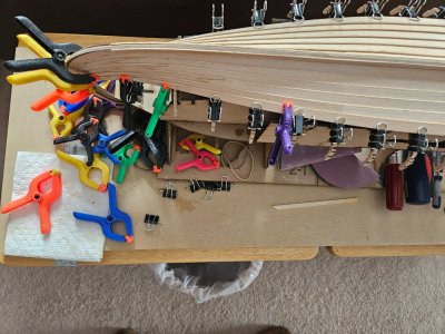
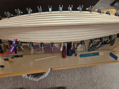
Oseberg - Ver. 3 - Pavel Nikitin - 1:25

Any day now, my friend! ;)
Great news, my kit finally arrived yesterday...Jan. 27, 2025!!!

The not so great news, it must have been dropped somewhere in the shipping process. At first it just looked as though the outer plastic and styrofoam wrapping was damaged but still intact. When I opened it up I realized the box itself had substantial damage on what I will call the back left corner, I was heartbroken. I searched through all of the parts to make sure they were all there and intact, I was lucky...the damaged corner is where there was extra styrofoam inside the box where all of the MDF plates were packed. I found no damaged parts, excellent job Pavel and Denis!!!

Hopefully I can get started on it this weekend, I'm looking forward to this build!
Steve

Looks like you dodged a bullet there! I was impressed with the packaging of my kit as well. I'm glad there was no damage. Whether or not you decide to do a build log (I hope you do), at least post a few pictures of your progress. :D
 
Preparing the strakes

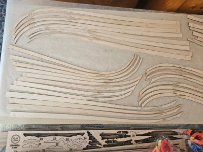
I've spent the past week's evenings preparing the planking strakes. Following Pavel's lead in his video, I lightly marked each piece with the plank number. Because the pieces on each course are symmetrical, you can alternate which faces is up between the sections that are glued together (Pavel shows this). This takes advantage of the bevel on the laser-curt edges. You only need to very gently sand the tips of the points until you get a snug fit. The inside edges do not have to be touched. Very light touches with fine sandpaper is all that is needed. Pavel uses spring clamps to clamp the pieces together across the width of the strake, but that mad me nervous. I used painter's tape to hold the pieces together on a scrap piece of Corian that the glue won't stick to. This has the added advantage of keeping everything flat while the glue dries.

20250127_183102~2.jpg
20250201_120301.jpg
20250201_120306.jpg

So, the next step is to apply the strakes ... or so I thought. Watching Pavel's next video, I see that the next step is to taper the ends of the stems - you know, the ones I so carefully fit the supports on the jig to. Oh well, I figured if the jig needed adjustment, I would just handle it.

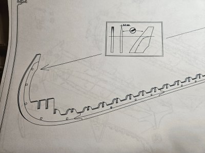
This is another area where the videos are a must. If you look at the instructions, you'll see that the amount to taper is approximately 20mm.

20250120_185014.jpg

On the video, however, Pavel has you taper the last 60mm. Another case where it would be challenging to build from the instructions alone.

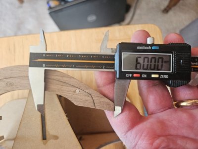
He clamps the boat's frame sideways on the jig, but a clamp made me nervous, so I used rubber bands to hold it in place and supported the part I was sanding with my hand. The first side is sanded until the very tip is 2.5mm thick. Then you sand the other side until the tip is 0.5mm thick. Using a craft stick with 80 grit paper glued on, it took about 15 minutes to get each bevel sanded (x 4).

20250201_113007.jpg
20250201_110854.jpg
20250201_113218.jpg
20250201_121530.jpg
20250201_123252.jpg

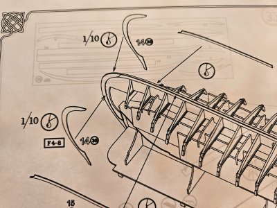
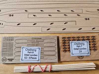
The next step is to glue temporary cheek pieces onto the stems. Pavel shows only applying tiny drops of glue as these are only to be guides while the strakes are being applied. They will be removed later. Looking at the instructions, you might be able to figure out what the "1/10" next to the glue symbol means. ;)

20250201_151028.jpg
20250201_140305.jpg

The cheeks don't exactly follow the curve of the stem, but hopefully the carved walnut pieces that replace them will fit better. Either way, it can be dealt with. My concern with the newly modified stems fitting back into the jig were unfounded. They fit back in perfectly! After that, the keel cheeks are glued on and then it's time to plank! :D

20250202_102214.jpg

There are a few enhancements that I have been planning since before I even received the kit. One of these have to do with the strakes. Any photographs of the actual Oseberg show that the builders put a decorative (I assume) double bead along the lower edge of each strake. This is also where the rivets were placed (another enhancement I plan, but let's not get ahead of ourselves.)

web_hent_bilde.jpg
(Photo credit Unimus Portalen Cultural History Museum, Archeology) This site has a lot of great reference photos of the Oseberg.

I attempted to get as close to scale as possible. They are just a tiny bit larger than they should be, but they are as close as I could get with what I had.

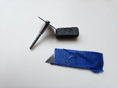
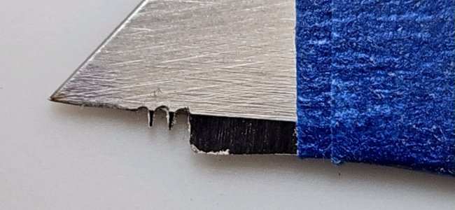
To accomplish this, I made a scratchstock from a utility knife blade. Using the dressing stone from Dremel, I dressed the edge of the thinnest cutoff wheel they make into a rounded profile. Using this, I carefully ground some slots into the blade right next to one another and cut away the rest. I filed the edges that would contact the face and edge of the strake so they wouldn't mar it. Then, repeated light passes will cut the grooves into the strakes. It takes a while - and many passes, but can be cathartic.

20250202_084922.jpg
20250202_084958.jpg
20250202_085033.jpg
20250202_085050.jpg

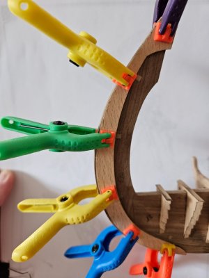
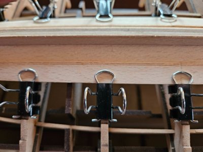
The first strake is applied and clamped with modified binder clips and spring clamps.

20250202_102233.jpg

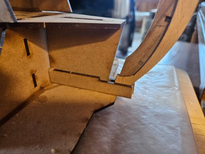
The apparent gap between the strake and keel must be a shadow, because there isn't one on the model.

That's where I am so far. Now I have a lot of scraping and fitting to do. Sigh.
 
Planking (cont'd)

Work continues on the planking. Progress is slow as each plank must fit a certain way while being twisted and bent. Adding the bead detail also takes some time, but I feel it is well worth it. I will need to experiment with some finishing techniques that won't make the detail completely disappear, yet doesn't make it stick out like a sore thumb either. Subtlety is the order of the day.

20250208_081000.jpg
20250208_081023.jpg

I had mentioned earlier that there were some other enhancements I was going to make. A couple of these have to do with the oars and the oar holes in the top strake. Here is what is provided in the kit:

20250208_090417.jpg

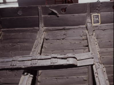
First, the oar holes in the strake of the actual Oseberg do NOT have 2 diagonal slots - there is only one - on the aft side of the hole and angled upwards.

1739024022545.png

This makes perfect logical sense as the oarsmen would be facing aft as they rowed and the pressure from the oar shaft would always be on the forward side of the hole. If you had a slot there, it would create a weak point in the plank and would surely break away from the stress.

I ordered some beech from Dave at the Lumberyard to recreate these upper strakes correctly. The color of the replacement wood is a good match, although it doesn't have the flecks of grain that Pavel's has. Most of it will be hidden by the shields anyway, so that is not a big deal.

Second, the oar hole covers. While other Viking ship finds have oar hole covers to keep from shipping water while under sail, there is no evidence of these ever being used on Oseberg. There were never any found, nor are there any remains of holes or hardware to attach them. This has led researchers to believe that this boat was more of a ceremonial ship and was seldom, if ever, taken out on the open seas - more likely to have been sailed on protected inland waters.

As for the oars, while I understand the need for making the kit more accessible to the average builder by providing 2 piece oars, that is not how they were built. Nor were the blades as wide as his with respect to the shaft. A video from Olha Batchvarov shows her making proper one piece oars which is what I plan on doing. In that video, she shows a page of oar dimensions from the book, The Oseberg Ship: Reconstruction of form and function by Vibeke Bischoff.

1739024926560.png

This book, if you can find it at all, is quite expensive. I did find a copy, however, at the Cornell University library, so I applied for and received an off-campus library card and I'll be heading to Ithaca today to pick it up. Until next time...
 
Last edited:
While installing strake #3, I discovered that two of the second jig frames sit a little too high and the strake doesn't clear them. I have added an edit to my post #38 that illustrates this. They can be easily trimmed at this point, but would be even easier before you assemble the jig.
 
Preparing the strakes

I've spent the past week's evenings preparing the planking strakes. Following Pavel's lead in his video, I lightly marked each piece with the plank number. Because the pieces on each course are symmetrical, you can alternate which faces is up between the sections that are glued together (Pavel shows this). This takes advantage of the bevel on the laser-curt edges. You only need to very gently sand the tips of the points until you get a snug fit. The inside edges do not have to be touched. Very light touches with fine sandpaper is all that is needed. Pavel uses spring clamps to clamp the pieces together across the width of the strake, but that mad me nervous. I used painter's tape to hold the pieces together on a scrap piece of Corian that the glue won't stick to. This has the added advantage of keeping everything flat while the glue dries.

View attachment 499039
View attachment 499040
View attachment 499041

So, the next step is to apply the strakes ... or so I thought. Watching Pavel's next video, I see that the next step is to taper the ends of the stems - you know, the ones I so carefully fit the supports on the jig to. Oh well, I figured if the jig needed adjustment, I would just handle it.

This is another area where the videos are a must. If you look at the instructions, you'll see that the amount to taper is approximately 20mm.

View attachment 499044

On the video, however, Pavel has you taper the last 60mm. Another case where it would be challenging to build from the instructions alone.

He clamps the boat's frame sideways on the jig, but a clamp made me nervous, so I used rubber bands to hold it in place and supported the part I was sanding with my hand. The first side is sanded until the very tip is 2.5mm thick. Then you sand the other side until the tip is 0.5mm thick. Using a craft stick with 80 grit paper glued on, it took about 15 minutes to get each bevel sanded (x 4).

View attachment 499046
View attachment 499047
View attachment 499048
View attachment 499049
View attachment 499050

The next step is to glue temporary cheek pieces onto the stems. Pavel shows only applying tiny drops of glue as these are only to be guides while the strakes are being applied. They will be removed later. Looking at the instructions, you might be able to figure out what the "1/10" next to the glue symbol means. ;)

View attachment 499051
View attachment 499052

The cheeks don't exactly follow the curve of the stem, but hopefully the carved walnut pieces that replace them will fit better. Either way, it can be dealt with. My concern with the newly modified stems fitting back into the jig were unfounded. They fit back in perfectly! After that, the keel cheeks are glued on and then it's time to plank! :D

View attachment 499053

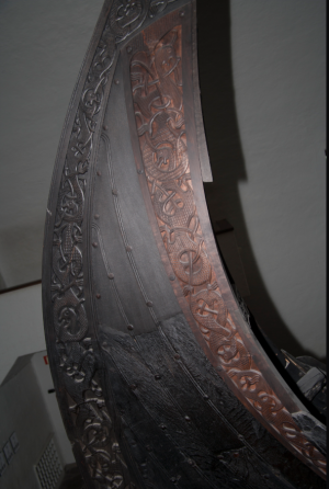
There are a few enhancements that I have been planning since before I even received the kit. One of these have to do with the strakes. Any photographs of the actual Oseberg show that the builders put a decorative (I assume) double bead along the lower edge of each strake. This is also where the rivets were placed (another enhancement I plan, but let's not get ahead of ourselves.)

View attachment 499054
(Photo credit Unimus Portalen Cultural History Museum, Archeology) This site has a lot of great reference photos of the Oseberg.

I attempted to get as close to scale as possible. They are just a tiny bit larger than they should be, but they are as close as I could get with what I had.

To accomplish this, I made a scratchstock from a utility knife blade. Using the dressing stone from Dremel, I dressed the edge of the thinnest cutoff wheel they make into a rounded profile. Using this, I carefully ground some slots into the blade right next to one another and cut away the rest. I filed the edges that would contact the face and edge of the strake so they wouldn't mar it. Then, repeated light passes will cut the grooves into the strakes. It takes a while - and many passes, but can be cathartic.

View attachment 499056
View attachment 499057
View attachment 499059
View attachment 499060

The first strake is applied and clamped with modified binder clips and spring clamps.

View attachment 499061

The apparent gap between the strake and keel must be a shadow, because there isn't one on the model.

That's where I am so far. Now I have a lot of scraping and fitting to do. Sigh.
I always thought I had a good eye for detail but you definitely put me to shame, I never noticed the double bead on the planks. Awesome job adding that extra detail!
 
The Keel

Still working from videos because the manual had not yet been sent, I started assembling the keel. This is where I made my first mistake of the new year. That's my quota, so no more allowed. ROTF

The keel is made in two layers, with each layer having 6 pieces. The idea (as shown on the video) is to assemble each layer, then laminate the two layers together. There are small square holes that line up between the two layers where you are to drive square pegs to align the layers and strengthen the assembly. On his video, Pavel assembles each layer freehand. The joints are designed where this is plausible, however he starts gluing without any apparent cleanup of the char from the laser cutting - he just puts glue on the mating surface and pushes the parts together.

Now, anyone who has ever assembled a model with laser-cut pieces, knows that the cut edges are slightly beveled due to the laser burning away more at the top surface of the sheet than at the bottom. The thicker the piece, the more noticeable the taper. The joint is in sort of a zig-zag pattern and when I placed the two parts together, there was a gap of nearly 1mm where the parts wouldn't mate due to the taper. Pavel simply pushed the parts together and filled in the gap with glue (granted, you can't see the actual gap, but you see him wipe glue into the crack). A glue joint in wood that is mostly glue will not hold, so I very lightly sanded the mating surfaces to square them up and make the joints fit.

Pavel then simply applies glue to one of the layers, paces the other on top and starts driving pegs. Easy-peazy!

Wellllllll, when I stacked the two layers up, one was noticeably longer than the other! :oops:

View attachment 494454
View attachment 494455View attachment 494456

Now, there is NO WAY I sanded THAT MUCH MORE from one layer than the other! I barely touched the edges - just enough to get rid of the daylight showing in the joints.

Comparing the layers to the full sized drawing, I found that one of them was really close, less than 1mm off. It, fortunately, was the shorter of the two, so I left it as is. Comparing the square peg holes, I realized that they gradually diverged from one another along the length, so I would not be able to just make one cut to fix the problem. I ended up making 7 cuts along the length. I then glued each section to the good layer as I completed adjusting it - driving pegs as I went.

View attachment 494457

IMPORTANT - laminating these two halves with white glue WILL CAUSE THEM TO CURL due to the moisture in the glue. Be sure to have LOTS of small clamps, or two boards and large clamps (or water bottles, as Pavel shows).

I would suggest building one layer over the plans and then fitting the second layer to the first as you assemble it.

I have the char cleaned up from the edges now and just need to sand the faces, tapering them as directed.
I received my kit two weeks ago and I'm moving at break neck speed, I finally finished the first slipway/jig last weekend. LOL

I'm not totally pleased with how it turned out, it has a 2 to 3mm warp to it from stem to stern...I guess I should have sanded the joints of the bottom two runners to make sure they were perfectly flat before I glued them together.

I'm super glad I came across your build log, I would have just followed Pavel's video and glued everything together without sanding the keel parts and found out the hard way that nothing fits as it's supposed to. I'm going to follow your advise and sand down the 5 piece half of the keel to match the blueprint and make the 6 piece half match it.

I've seen some other threads and videos of people building v2 and v3 of this kit and saying the hull planks are too short, I have to believe this has to be a big part of that.

Thanks again for your detailed build log, it's really helping me!
Steve
 
Thanks again for your detailed build log, it's really helping me!
Thanks for following along Steve. I will try to point out issues I find along the way. I'm hoping to get as far as I can before spring comes and all the outdoor chores manifest themselves. :D I hope everyone keeps in mind that I am no expert, I'm figuring things out as I go and hoping to keep others from falling into the traps I find.

Congrats on receiving your kit and getting started on it. As far as the warped jig, I think that if you can get the slots in the ends that hold the stems parallel with one another, you should be ok. As I mentioned earlier, the jig doesn't hold the frames tight enough to keep them in perfect alignment, plus the two stringers will make the frames go where it wants them anyway. I had to adjust a couple of frames afterward. As long as the stems are parallel, I don't think you'll have a warped frame. Split the difference between the two stem slots, taking a little off one side of one end, and off the opposite side of the other end. Then just add a piece of scrap to the opposite sides of the slots to trap the keel stems.

I've got 4 runs of strakes done so far. I haven't run into any being too short, but they are pretty narrow at the stems. Don't be afraid to adjust the ends at the stems for a good fit and an angle that will allow the strake to be bent around the bilge. I've had to sand-fit-sand-fit-sand-fit maybe 15 to 20 times before getting a good fit. Have patience. The edges of some of them just barely (and I mean barely) overlap the previous one at the stems. I've also had to adjust the notches in the last couple of frames as well.

I hope all of this makes sense. It should once you get to that point. If not, just ask and I'll do my best to help.
 
hemselves.Thanks for following along Steve. I will try to point out issues I find along the way. I'm hoping to get as far as I can before spring comes and all the outdoor chores manifest t :D I hope everyone keeps in mind that I am no expert, I'm figuring things out as I go and hoping to keep others from falling into the traps I find.

Congrats on receiving your kit and getting started on it. As far as the warped jig, I think that if you can get the slots in the ends that hold the stems parallel with one another, you should be ok. As I mentioned earlier, the jig doesn't hold the frames tight enough to keep them in perfect alignment, plus the two stringers will make the frames go where it wants them anyway. I had to adjust a couple of frames afterward. As long as the stems are parallel, I don't think you'll have a warped frame. Split the difference between the two stem slots, taking a little off one side of one end, and off the opposite side of the other end. Then just add a piece of scrap to the opposite sides of the slots to trap the keel stems.

I've got 4 runs of strakes done so far. I haven't run into any being too short, but they are pretty narrow at the stems. Don't be afraid to adjust the ends at the stems for a good fit and an angle that will allow the strake to be bent around the bilge. I've had to sand-fit-sand-fit-sand-fit maybe 15 to 20 times before getting a good fit. Have patience. The edges of some of them just barely (and I mean barely) overlap the previous one at the stems. I've also had to adjust the notches in the last couple of frames as well.

I hope all of this makes sense. It should once you get to that point. If not, just ask and I'll do my best to h
 
Planking (cont'd)

The planking continues slowly. I didn't get as much time to work on her this weekend as I had hoped because the Covid cooties came calling Saturday morning. Feeling better now, but still recovering, so just a couple of thoughts and pictures for now.

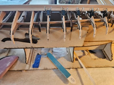
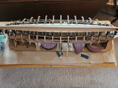
The strakes are a tricky fit where they curve up to the stems. Having plenty of clamps of different types and sizes is a necessity. I have even used rubber bands in some circumstances. Pavel includes some "clamps" to make with dowels, but I didn't even bother. In many instances, the jig gets in the way of the clamps, so you have to improvise with whatever you can.

20250217_153649.jpg

20250217_153658.jpg

Forming the double bead on the edge of the strakes has also taken a lot of time. It's a small detail, but I think it will be worth it.

20250217_153804.jpg

The book The Oseberg Ship that I mentioned earlier is a wealth of knowledge on this ship. There are drawings with dimensions made from the original parts. I will try to convey as much of that information as I can without violating copyrights. Oh, yeah, the cross beams in the power frame that I was calling thwarts for lack of a better term are actually called bitis (pl), biti (sin). This is definitely a book that I will purchase as soon as I can find one for sale.
 
Even with Covid you're making good progress.
Well Jan, the worst couple of days are past, so, since I can't go back to work yet (still testing positive), I can either sit in front of the TV and cough, or sit at my worktable ... and cough. :D

Just came upon your build report and wanted to share my appreciation for your attention to detail and skillful woodworking.
Thank you Paul. I've seen your work and am honored that you would say that.
 
You have me wondering what the slight differences in the fitting of the strakes is caused by. I found working on the SB that there were planks that fell short at the stern. I thought it was my error but found that a couple of the other SB builders had the same experience.

Jan
 
You have me wondering what the slight differences in the fitting of the strakes is caused by.
Jan, I was wondering the same thing, so I've spent the time since your posting trying to figure out what's going on.

Clearly, as seen below, if I try to attach a raw, unsanded strake to fit the curve of the stem, it won't reach the previous one to overlap it. This is the problem I have faced since the first strake,
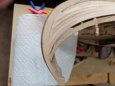
20250218_101201.jpg

Once I fit the end of it so that the strakes meet, however, then the new one is angled so far towards the keel, that significant pressure must be exerted to conform it to shape.
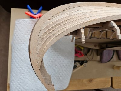
20250218_101246.jpg

Where you see the strake overlap in the first 3 or 4 cm, it is just barely overlapping. In my attempt to fit this one last night, I partially broke it at the glue joint you see at the first frame. I glued it back together and called it quits for the evening.

I thought about wetting or steaming them to try to edge-bend them. That would work if the grain followed the curve of the bend, but it doesn't. Remember, these pieces were cut from a straight-grained sheet of wood. If I moistened the wood, it would only weaken it and applying lateral pressure would surely make it split along the short grain.

Keep in mind that I have only been trimming the barest minimum necessary at the tip of the strake to get it to fit. I then wondered if maybe I was being too conservative and would have an excess of material once I reached the last strake. I decided to dry-clamp the strakes up to #10 to see.
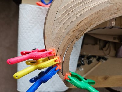
20250218_101900.jpg

Well, I guess that theory has been shattered. Despite my minimalist approach to fitting, it appears that there will not be enough material to reach the tip of the stem, even if I trim no more!

I decided to go back to Pavel's videos and try to see what he did. Video #9. Planking Part 2 ends with only strake #4 attached.

1739895370993.png

I am working on strake #7. His next video, #10 is titled, "Painting Timbers" and he decided to attach strakes 5 through 9 off-camera. Well, a lot of help that was. :confused:

1739895583003.png

Looking carefully, you'll see that even his strake #9 falls short of the corner of the stem guide piece (the one that is just temporarily glued on.)
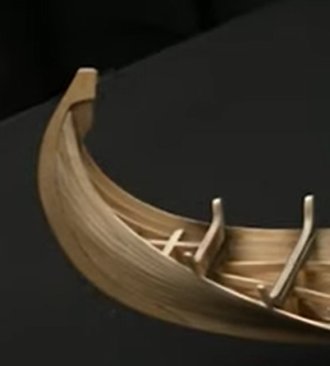
1739895785751.png

My only option at this point is to continue on as I have, carefully fitting with sandpaper and gentile pressure. If (when) I end up short at the stems, I will just have to deal with it as best as I can. Perhaps I messed up early on, but I've really tried to be careful and remove the least amount of material as possible.

I should also point out here that Pavel stops at strake 9 to paint the frames with his patina and tint. This makes sense to make it easier to sand around the sides of the frame afterwards. His next video, #11, dives right into the decking - still only having 9 strakes installed. If you were building from his assembly manual, you would have planked all the way out to #12, the sheer strake and modified your jig into a cradle before starting the decking.
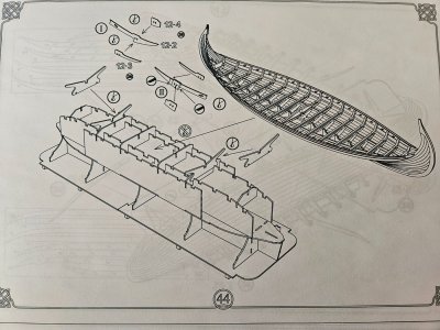
20250218_112717.jpg

While we have this page of the manual in front of us, there is an important detail that i must point out. The drawing has the bow oriented towards the upper left and the stern at the lower right. You can tell this by the position of the mast step, which is located on the aft side of the central biti. The location where he drew the detail for the steering oar reinforcement would lead you to believe that it should be placed at that end of the ship. IT IS NOT! The steering oar goes at the lower right end on the side away from you.

As a side note and while the vast majority of those on this forum already know this, here's a bit of nautical trivia for newcomers to ships and ship modeling. Before there were rudders on ships, as in the case of the Oseberg, a separate large oar was used to steer the boat. Most sailors were right handed, so the steering oar was placed over or through the right side of the stern . Sailors began calling the right side the steering side, which soon became "starboard" by combining two Old English words: stéor (meaning "steer") and bord (meaning "the side of a boat"). As the size of boats grew, so did the steering oar, making it much easier to tie a boat up to a dock on the side opposite the oar. This side became known as larboard, or "the loading side." Over time, larboard—too easily confused with starboard—was replaced with port. After all, this was the side that faced the port, allowing supplies to be ported aboard by porters. (Source National Ocean Service - NOAA)
 
Thank you Russ, for posting this great explanation. It's great piece of research of cause and effect. I think I remember some similar problems on one of the other Viking kit builds. The solution was to work from the stem to midships and add a small piece between the strakes. Don't know if I got that right but then I'm an old guy and don't have to be right all the time..

Jan
 
Back
Top