Pocher 1:8 scale Lotus 72 [COMPLETED BUILD]

Hi Dean. I speak from memory Dean, but I think the twin side fitted radiator design also made room for the brake assemblies to be mounted inboard and reducing the unsprung weight of the suspension and wheel- a first for F1 cars. Most definitely one of the best looking F1 cars but not my favorite - Nigel Mansell 1992 Williams.

Looks like fun and I will pull up a chair and follow this. Cheers Grant
My taste in F1 cars goes back to the old classics. It is hard for me to pick a clear favorite, but the Lotus 72 is in my top 5 for sure! ;)
If I had to pick one, it would most likely be the Eagle Gurney-Westlake V-12.
After that?
Lotus 72
Lotus 78
McLaren M23
Ferrari 312T
Williams FW07
 
Bad news and Good news...

First the Bad
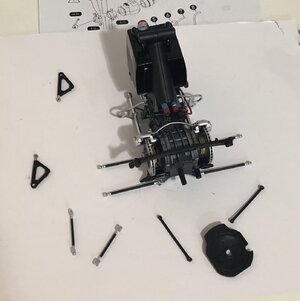
... while gathering pieces for the next step...
1684953543657.png
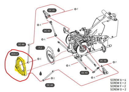
I couldn't find piece DCA-2! Certainly it couldn't have been lost by me, because I don't remove parts from the trays (die cast pieces) or sprue (plastic pieces) until they are needed.

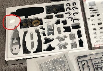
So I checked my photos showing the contents when I first unpacked the kit...
Screenshot 2023-05-24 132242.jpg

Sure enough, there is the empty cavity for the die cast part DCA-2 shown above. I never noticed it...sigh!
I need this part to couple the transmission with the motor! And trust me, I turned my entire room upside down and searched through the entire contents of the kit to no avail! I find it hard to believe it would have fallen out and not be in sight anywhere.

So I contacted the store that I purchased the kit from, and they gave me an email address...dead end! So I got online at the Pocher website and found a phone number for the US customer service contact. I called and got a voice mail saying to email customer support. I emailed customer support and got a reply saying they will get back to me within two days! Sigh!!!!

So I have a few choices at this point, wait and see if I can get the part in a timely manner, or... I have to design one in Cad and print it in plastic.
This part has brackets that the struts attach to, and it should be fine in plastic, however I don't know the exact thickness, and that determines the distance between the struts that go from the rear suspension to the front of the motor. I will have to assemble a lot of suspension pieces to accurately determine that, and then take it all apart again. So it is doable, but I am hopeful they will respond in a timely manner and get me the part I paid for, so I don't have to make my own part (which will be very time consuming)! Plus I prefer the die cast piece for strength reasons.

And finally, how did that leave the Pocher factory with a part clearly missing from the tray? The kit was sealed and I had to cut it open. Given the cost, I would have expected a better quality control. :(

Now the good news!
There are many more sub assemblies that I can work on while waiting to see how this plays out. I was excited to see the motor and rear end come together, but it all has to be done eventually. So working on other sub assemblies will keep my build moving forward. I just won't be working in the same order as the instructions. ;)
 
Last edited:
Dean I'm glad to hear you have a good albeit difficult work around for this missing piece should your first attempt at replacement fail.
Thank you Daniel. I can create the part, but it will be very time consuming. So instead of taking a few seconds to take it out of the tray, it would take days of work to duplicate it. Hopefully that won’t be necessary. ;)
 
A missing part is rather annoying, putting it mildly. Being able to work on other subs is hardly a consolation.
I hope you'll receive your missing part sooner rather than later. I have mixed experiences with shipment of missing parts
 
A missing part is rather annoying, putting it mildly. Being able to work on other subs is hardly a consolation.
I hope you'll receive your missing part sooner rather than later. I have mixed experiences with shipment of missing parts
It is very frustrating, however I heard they have good customer service regarding that. So time will tell.... ;)
 
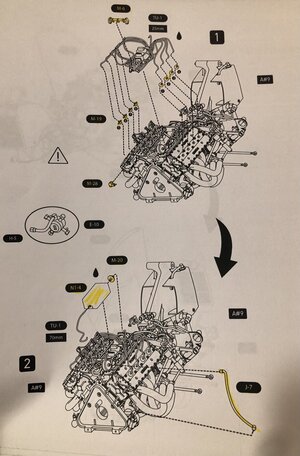
After that is done, the next step is to join the motor assembly with the rear end assembly. That’s on hold. So the next step after that is below…
IMG_1293.jpeg
I assume they wait until the two assemblies are joined to continue on the motor details because they are more likely to be broken. But I will just have to be careful! ;)
So those were added and this step completed.
View attachment 376259
View attachment 376260
IMG_1295.jpeg

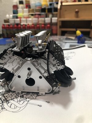
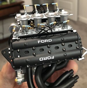
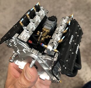
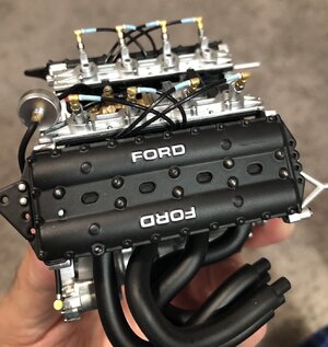
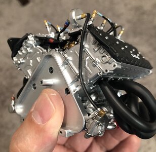
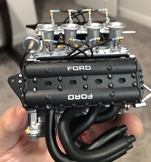
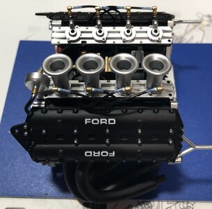
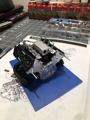
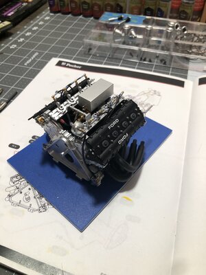
I put the velocity stacks on temporary to see what they are going to look like. I sanded the edges where they were cut off the sprue and did some touch up paint and finally added a wash down at the bottom of them. Happy with the look.
Ps - I was going to make small screens for the velocity stacks, which would look cool. But after doing some research I found out race cars don’t use them because they break up the laminar flow of air in the stacks at the expense of power. So screens are more suited for street cars. In addition, I learned that the height determines the Rpm range that the velocity stack increase’s torque! Shorter ones increase torque at low rpms and taller ones at higher rpms. Makes sense due to how they work. ;)
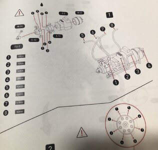
The hose that is not connected will be attached to the fuel injector housing in the upcoming steps.
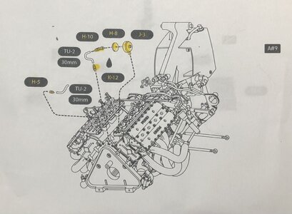
So next will be the distributor and injector housing assembly that will allow me to add the injector tubes and spark plug wires! ;)
 
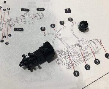
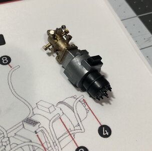
Next step…the distributor and injector housing assembly. There will be an ignition box sitting on top of this that will cover most of it, but we still have to treat it like it will be seen! ;)
IMG_1303.jpeg
The parts are all black plastic…
IMG_1299.jpeg
I painted it and added the hoses…
IMG_1306.jpeg
IMG_1309.jpeg
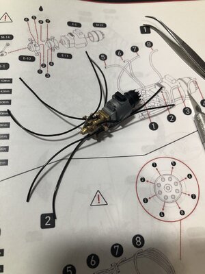
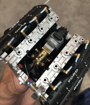
Then it was glued to the motor… and the tubing was run and cut to length…
IMG_1312.jpeg
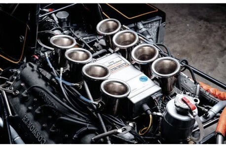
Using this image as reference…
IMG_1310.jpeg
As you can see, the tubing is actually a clear blue color and there is a black tubing for insulation over that. But the ends are clear and have a white piece that usually has the cylinder number on it.
So I tried to simulate that the best I could with paint…
IMG_1317.jpeg
IMG_1311.jpegIMG_1313.jpegIMG_1314.jpeg

And a peek at it with the velocity stacks… ;)

IMG_1317.jpeg
Tomorrow evening will be time for the spark plug wires! Fun stuff! ;)
 
Last edited:
Great discussion on velocity stack heights and what they do. I learned something. I love the contrasting colors in the engines plumbing.
Thank you Daniel! I learned myself when looking into screens for the velocity stacks.
The AN type connectors were blue and red, which was common for hose fittings, and some of the others were either silver or gold. It does make it more interesting visually. ;)
 
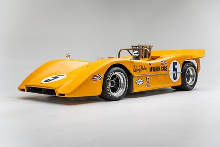
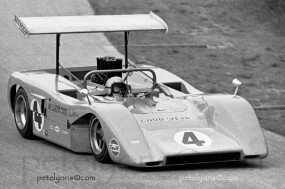
My favorite CanAm series showing velocity stacks circa 1969.
Jim Pace Motorsports has some great YouTube videos with sound which is awesome.
View attachment 376322
I have that car in my collection! ;)
And I stand corrected, because I have seen screens on race cars, but it was not that common to my knowledge. Perhaps some of the mechanics didn't know that would break up the laminar flow through the velocity stack?
 
I have that car in my collection! ;)
And I stand corrected, because I have seen screens on race cars, but it was not that common to my knowledge. Perhaps some of the mechanics didn't know that would break up the laminar flow through the velocity stack?
You know it's possible the screens were taken off while racing and put back on while the vehicle was in the shop just to keep errant material from getting in while
unsupervised.


CA69Elk_McLaren4b-285x189.jpg
 
Last edited:
Last edited:
Back
Top