Thanks Grant! I know you’re over there in CHARville…and I am here in PAINTland.Good afternoon Dean. Just caught up here. Very very cool!! Cheers Grant

Glad you stopped in.
 |
As a way to introduce our brass coins to the community, we will raffle off a free coin during the month of August. Follow link ABOVE for instructions for entering. |
 |
 |
The beloved Ships in Scale Magazine is back and charting a new course for 2026! Discover new skills, new techniques, and new inspirations in every issue. NOTE THAT OUR FIRST ISSUE WILL BE JAN/FEB 2026 |
 |
Thanks Grant! I know you’re over there in CHARville…and I am here in PAINTland.Good afternoon Dean. Just caught up here. Very very cool!! Cheers Grant

True story…..I’m feeling a tad charred right now.Thanks Grant! I know you’re over there in CHARville…and I am here in PAINTland.
Glad you stopped in.

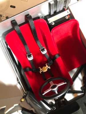
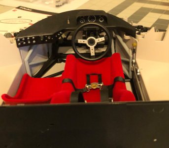

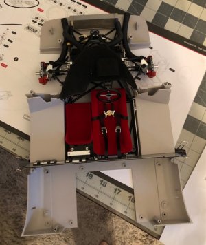
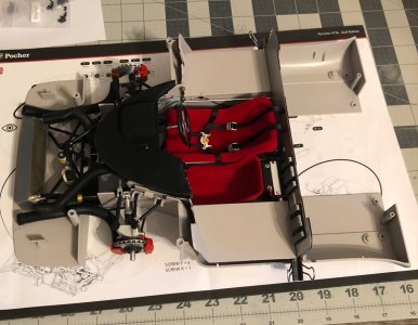

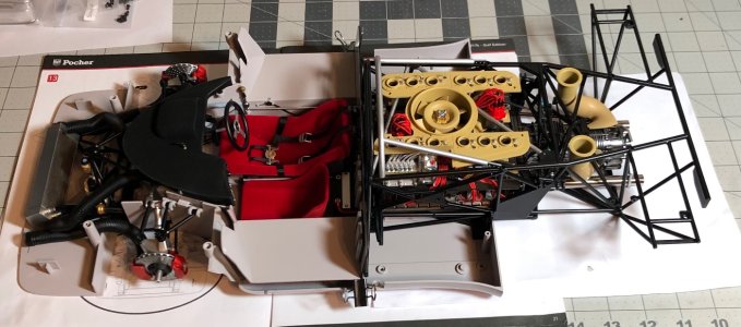
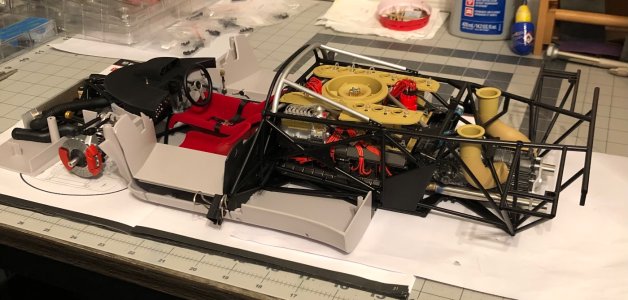
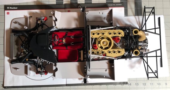
Thanks, they came that way, top of dash too.Very nice! The seats appear to be flocked. Did you do that or were they provided that way?
Thanks Jan!Wow, the detail, absolutely fascinating to watch all the pieces come together.
Jan

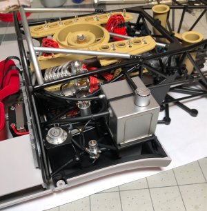
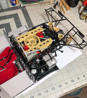
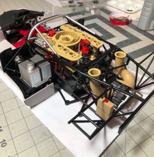
It certainly does Dean. Did you use like a brown based or black based wash?I am glad I did a wash on all the parts, it definitely adds realism.
Thanks Daniel, it is brown based.It certainly does Dean. Did you use like a brown based or black based wash?
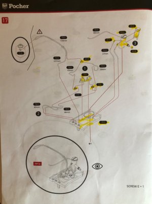


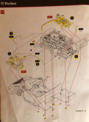
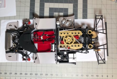
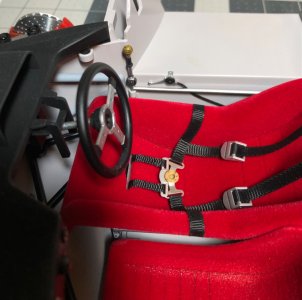
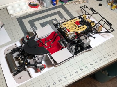
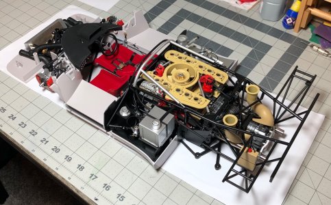

Your touch-up of several details makes it special, Dean. It was also by the build of the Ducati that you have to look on several pages to find how some lines and tubes are running. But with it’s function in mind you can best reason how they should run.On to sub assembly A#16…
View attachment 508776
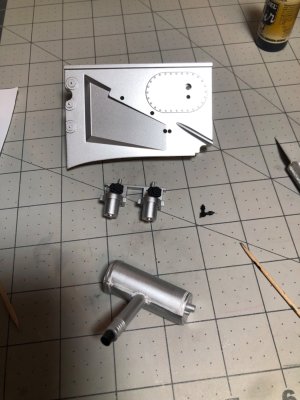
The parts as provided…I started gluing them together in preparation for painting…
View attachment 508777
As you can see there is no way I would put them on like this! Paint and detailing required…
Then assemble…
View attachment 508778
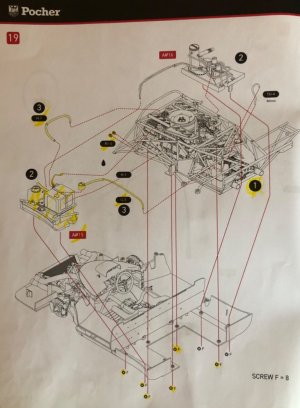
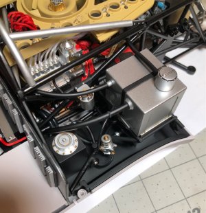
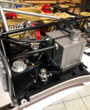
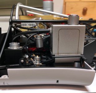
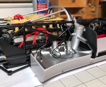
The fuel lines run across to the other side to the black can and then to a pump and thru the filter and finally to the injector manifold…
View attachment 508779View attachment 508780
So time to finalize this step…
View attachment 508781
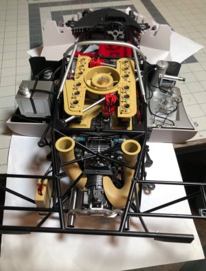
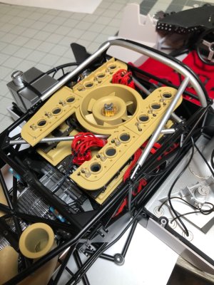
I ran the last of the hoses for this step and I am happy to finally have all of the sub assemblies and additional hoses put together.
Complaint - the majority of the pins on the parts the hoses attach to were smaller than the ID of the hoses being attached…sigh! You can’t even glue them on. Solution - I came up with the idea to put some PVA glue on a toothpick and spread it around the OD of the pins and let dry, and repeat until the pin diameter was large enough to attach the hose firmly. Whew!
Pics…
View attachment 508782View attachment 508783View attachment 508784
She’s at 20” long now, and about 10” wide. And she’s getting heavy!
A picture of the wooden shifter knob…I clear coated it and I think it looks better.
View attachment 508786
A few final pics…
View attachment 508787View attachment 508788View attachment 508789
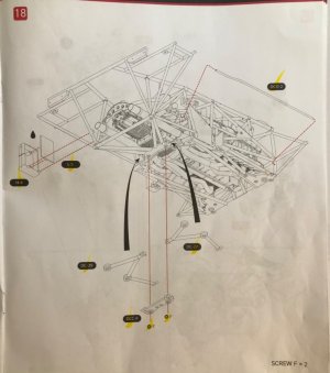
She’s really coming together nicely, despite a few challenges here and there. The instructions are definitely a bit ambiguous! You have to look at the pages after the step you’re working on sometimes, to see where things go. Some of the lines go to places not shown. Good thing they have some nice 3D illustrations. And having knowledge of cars is a definite plus.
Next will be working on the rear axles and then the rear suspension and brakes. That should be fun…no hoses!
Perhaps a tip for other (future) builders: In the Pocher manuals there is most of the time on the last page a overview of all the tubes with there lengt:You have to look at the pages after the step you’re working on sometimes, to see where things go. Some of the lines go to places not shown.

Thanks Peter! Knowing what the lines are for is a help for sure.Your touch-up of several details makes it special, Dean. It was also by the build of the Ducati that you have to look on several pages to find how some lines and tubes are running. But with it’s function in mind you can best reason how they should run.
Regards, Peter
The cars do not have that info, the last page is blank, and the first page covers screw sizes. The hose sizes and lengths are given when needed on a step. I didn't even use their lengths most of the time. I just ran the hose and cut it to the length that best suited the application. There is always extra left over.Perhaps a tip for other (future) builders: In the Pocher manuals there is most of the time on the last page a overview of all the tubes with there lengt:
View attachment 508877
While reading and paging through the manual I came across all the tubes with their number. I mentioned the relevant chapter number on the overview page. At the end I had both the beginning and the end of all the tube. With the 2nd build I did that first. That saves a lot of searching and puzzling later.
As an example by the Ducati: tube RF-02 has to be installed in chapter 5. But almost at the end in chapter 27 the end is attached.
I suppose it's the same with this build, Dean?
Regards, Peter
