Ro-marin Happy Hunter Tug-1/50-Multifunction RC

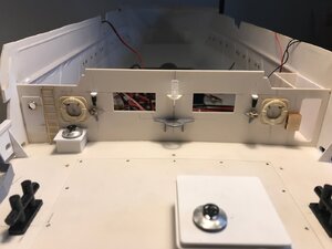
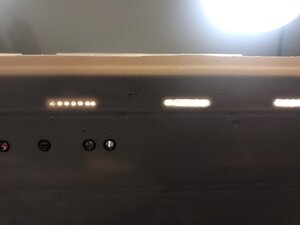
I have done some further detail work on the aft bulkhead.The small items above the pulleys are homemade bulkhead lights consisting of a bright white defused LED and plastic sheet.These are protected by black heat shrink acting as a mask for painting a little later on.

The lifebelts, central lamp moulding and the ply firebox are just mocked up for now and will be removed for painting.I have fitted two brass pins to the firebox to enable easy location after paint.The lifebelts are from my old kit hence the discolouration.A good scrub before paint should sort that.

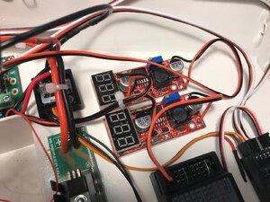
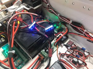
To enable the LEDs to work on 6volts,I have soldered 130 Ohm resisters inline in the positive lead.Red and Yellow LEDs will require a higher value resistor.The 6V batteries are greater than 6v when fully charger so adjustable voltage regulators with digital readout limit the supply voltage to 6v max.

Kind Regards

Nigel
IMG_1728.JPGIMG_1729.jpgIMG_1730.jpg
 
Thanks Guys

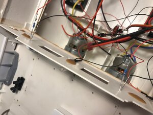
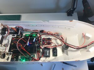
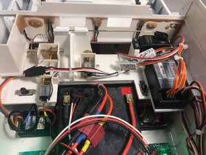
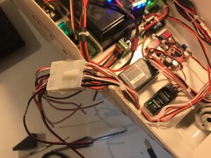
As I had two weeks holiday,I wanted to get the wiring done and tested as far as is possible.I needed to get my head into it and just keep going rather than doing bits now and again.I have managed that and things are now ready for gluing the next deck in place.
The motors are in place for the crane jib and hook as well as the tow release mechanism operated via a servo.I have fitted a multiplug to the wiring that goes to the superstructure to allow removal.
The crane rotation is taken care of by another motor and worm drive that is screwed to the underside of the next deck to go in.

Kind Regards

Nigel
IMG_1732.jpgIMG_1733.jpgIMG_1734.jpgIMG_1735.jpgIMG_1736.jpg
 
Hi Stephen

If you mean the two on off switches connected to the speed controllers, thats how they come from Mtronics from the factory.Once the controllers are calibrated they will become redundant as I will use the two distribution board switches currently sat on top of the 12v battery to turn the model on and off.The switches and battery volt indicators will go into small panels I have built into the next deck.
That will just leave the deliberately long battery leads free standing inside.I made them long so I can easily disconnect the Deans connectors for battery charging in situ.The Deans connectors do take some pulling apart.

Kind Regards

Nigel
 
Hi Nigel,
Good that I asked, I had assumed they might be a RX battery eliminator. Which I am quite sure you would know that having more than one battery eliminator feeding a RX in a common circuit is a problem.
The good news is the Deans plugs will loosen up as do most plugs.
Cheers,
Stephen.
 
Hi Stephen

I have disconnected ALL the battery eliminator feeds from the Escs.The receiver and decoders take their supply from the 6volt battery.I was told a long tome ago that the decoders run better on 6volts than 4.8volts.The receiver can take voltages up to 7.2v so no worries there;)
6v is fed to the receiver which supplies the decoders via the common rail.

Kind Regards

Nigel
 
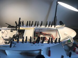
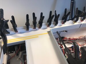
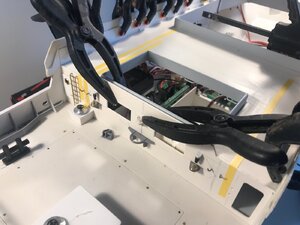
The deck and bulwark liners are now glued in place and drying.I glue the deck and liners in place in one operation as the liners clamp the deck down.The deck is pulling the hull into shape as it has pulled in at the top out of the mould.Hence the bigger clamps at the front.

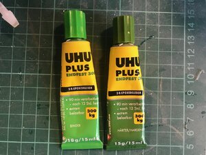
Whilst Stabilit Express is the best glue for ABS,this only gives me 5 minutes work time, no where near enough.For this I use UHU Endfest 300.Ninety minutes work time and a good bond to ABS styrene provided the surfaces are abraded.The excess will be removed with a scalpel when the adhesive is in a "green" stage in a few hours.

Kind Regards

Nigel

IMG_1737.jpgIMG_1738.jpgIMG_1739.jpgIMG_1740.jpg
 
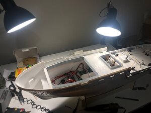
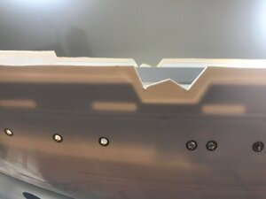
With the deck now bonded in place I turned my attention to opening the scuppers out.Using backlighting from my desk lamps,the outline is clearly visible from the bulwark liner.I chain drilled holes smaller than the scupper's height from the outside and started to rough out the shape.Final finishing is done with files and homemade sanding sticks(400 grade wet and dry cyano'd to lolly sticks).

Kind Regards

Nigel
IMG_1743.jpgIMG_1744.jpgIMG_1746.jpg
 
Last edited:
hi Nigel, it’s good to see someone else building this kit, although you are a little bit ahead of me. I have what might be a daft question, but if you don’t ask you don’t know. I’ve just finished building what is described in the instructions as the towing mechanism, but I can’t for the life of me see what it is meant to do. I’ve basically got a servo attached to a control rod that passes through 2 bushes, which opens and closes a gap between the 2 bushes. As far as I can see there is no further reference to this mechanism in any of the following instructions What is this meant to do and how is it intended to work ? Thanks Ian
 
Hi Ian

The idea is that a tow cable with a loop on the end is held in place by the rod.You can then tow other models.Moving the rod via the servo allows the tow cable to be released remotely.
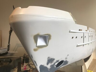
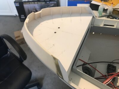
I am still working away on the build and will post some pics when I have finished the current step.A word of warning,I didn't trim any of the decks, they fit is near perfect.Until I got to the small deck at the bow.I have had to make a new one out of ABS sheet as it worked out 4 to 5mm short of the very tip of the bow.Also the mould guides on the outside of the hull are mmmm all over the shop.I filled them all using UPOL finishing putty from Halfords and marked the hull out to fit the d mouldings.

Kind Regards

Nigel
 
Hi Nigel,
oh I see, it’s simpler than I thought, and if Im honest a little underwhelming.
Thanks for the tip regarding the decks, I’ve got the rear deck secured in place and I’ve dry fitted the main deck, but based on you experience I think I’ll dry fit the bow before I go much further.
i‘m currently trying to get the gear boxes for the crane built, which is proving very difficult to get them to run smoothly, as you certainly already know the worm and wheel need to engage in a very precise manner otherwise they skip or stick making the movement very jerky. I’ve bought a couple of motors with ready built worm and wheel gear boxes from Amazon which work much better but now I’m trying to find a way of mounting these on the model.
Is it possible to show a photo of the problems on the outside of the hull, as you’ve probably guessed Im new to this game and I’m not sure I fully understand the issue
thanks for your help

Ian
 
Ian
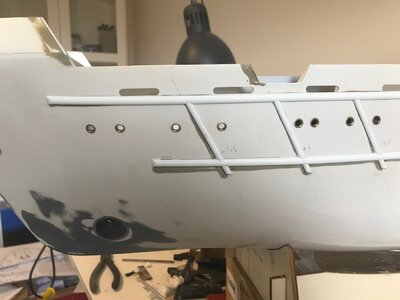
I will post a pic this weekend.It is easy to see as the locations are filled with grey putty and you can see where my d mouldings are positioned.If you follow the kit engravings the mouldings slope down at the bow end, it looks wrong they should be parallel to the deck line when viewed from the side.

Kind Regards

Nigel
 
Hi All
I have had things going on at home so what spare time I have had has been spent building, hence me not being around much at the moment.I had hoped to complete at Christmas but this has slipped a little,I do however hope to have the hull ready for paint before my holidays.
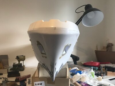
Little update of where I am at, all decks are on but as explained earlier I had to make a replacement foredeck as the kit item fell short at the bow by 4 to 5mm.This has also meant I had to extend the vac formed bow Bulwark.
You will notice I have cut the kit anchor pockets out.These were simplified to allow removal of the hull from the mould.The new ones follow the original.
Nearly all the side mouldings are on the hull.You can see how far out the kit moulded lines differ from my placement by the grey putty I have used.

Kind Regards

Nigel
IMG_1824.jpgIMG_1825.jpgIMG_1826.jpgIMG_1827.jpg
 
Uwe,yes I remember several kits by the German Manufacturers I used to drool over when younger.I have acquired a vintage untouched Hegi Oceanic tug kit from the 70's.Missing fittings, but these can be obtained or made.
I would like to see if Krick bring back the Berlin lifeboat with daughter boat.I has seen this built and it is a stunning model.

Kind Regards

Nigel
Hi Nigel,

You might be in luck.
I was in a model shop in Vegesack which is close to Bremen on Saturday and they had the Berlin lifeboat model, built and on display.
They also had the Graupner 1/200 Queen Mary 2 remote controlled model. (I was involved with building the real ship in Saint Nazaire, France in 2003).
They have virtually everything you need for RC model boats.
Their website address is www.modellbau-hasselbusch.de it’s well worth having a look at.

I build 1:1 scale cruise ships at Meyer Werft in Papenburg, Germany.

kind regards,

Beau.
 
Back
Top