


Hello friends of the baroque ship.
As I am starting the build of SAINT PHILIPPE in 1/64 let's do it in an proper way - click for music:
March de Triomphe
SP was launched in 1693 as replacement for the fire assisinated SAINT PHILIPPE of 1669 burnt down by the British after beaching the damaged hull.
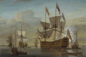
SP fought her only sea battle at Malaga 1704 and there are three paintings I do know from what only one shows a abbreviation of her:

The ship has got four gunports under the transom - but there does the similarity does find its end.
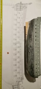
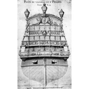
The other source we have got are lines and former plans

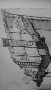
and a decorations drawing from the Toulon ship yard:


There are several differences to the Lemineur reconstruction published by Ancre - we will discuss these later on.

Here we can see the four instead of two gunports for the 36polounders under the transom and a pair of 24pounders integrated into the transom - nearly comoflaged in the structure.
I am very doubtful to this setting as in my opinion the recoil of the 24pfd gun is to much for


the slim timbers already holding the mass of decorational carvings and glass and balconies and columns. But as I told I will go deeper into this matter later on.
In a first step there are serious alternation between the plan of the transom balkonies and the Ancre solution (here shown in a scetch a cut along the center line) :

This maybe right due to some rebuilds done after the original pair of Toulon drawings

This painting shall show SP, twoo - but with one floor and row of windows less.
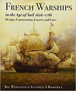
Even at Rif Winfield important book FRENCH WARSHIPS IN THE AGR OF SAIL 1626-1786 we do not get any proper answers to those questions.

And this contemporary painting of the battle of Malaga is a kind of bad if not dirty joke:

So there are a lot if doubts due to the transom's reconstruction. I my point of view Ancre pressed the reconstruction into a 90 barrels on carriages wearing hull - let's call them "counting guns"

not thinking about the swivel guns that may be in charge, too. But I am not in the situation to handle this case properly at the moment.
So what did I do yesterday? I paid nearly the price for the monograph again spent into ink plotter print outs in 1/64. And I have to admit that some of the plates are wrongly named due to the scale! (Keep this in mind when resize your plans!)
So the resulting hull is a beast of a ship still 1/4 smaller than the original plan - she will be fully rigged nearly four French feet long.

And is a beauty also as a hull model:

Here compared to the Heller hull I do transfer from SOLEIL ROYAL to SP:

Changing the scale to 1/92 so the hull fits better.
But st the very end the model will be a fully rigged one:

Myfirst step is to build a cardboardmodel for the first impression of the size and to get a feeling for the hill's shape. Let us call it a rough 3D-scretch to play with in the flat due to find a place for the proper model. So tomorrow I will reenter the Copyshop with the needed plans to get my working copies and cutout paper to be glued on the cardboards.
Hopefully you like this limited project as I will build it PoB due to my workshops limitations.
Thanks for your interest.
As I am starting the build of SAINT PHILIPPE in 1/64 let's do it in an proper way - click for music:
March de Triomphe
SP was launched in 1693 as replacement for the fire assisinated SAINT PHILIPPE of 1669 burnt down by the British after beaching the damaged hull.
SP fought her only sea battle at Malaga 1704 and there are three paintings I do know from what only one shows a abbreviation of her:
The ship has got four gunports under the transom - but there does the similarity does find its end.
The other source we have got are lines and former plans
and a decorations drawing from the Toulon ship yard:
There are several differences to the Lemineur reconstruction published by Ancre - we will discuss these later on.
Here we can see the four instead of two gunports for the 36polounders under the transom and a pair of 24pounders integrated into the transom - nearly comoflaged in the structure.
I am very doubtful to this setting as in my opinion the recoil of the 24pfd gun is to much for
the slim timbers already holding the mass of decorational carvings and glass and balconies and columns. But as I told I will go deeper into this matter later on.
In a first step there are serious alternation between the plan of the transom balkonies and the Ancre solution (here shown in a scetch a cut along the center line) :
This maybe right due to some rebuilds done after the original pair of Toulon drawings
This painting shall show SP, twoo - but with one floor and row of windows less.
Even at Rif Winfield important book FRENCH WARSHIPS IN THE AGR OF SAIL 1626-1786 we do not get any proper answers to those questions.
And this contemporary painting of the battle of Malaga is a kind of bad if not dirty joke:
So there are a lot if doubts due to the transom's reconstruction. I my point of view Ancre pressed the reconstruction into a 90 barrels on carriages wearing hull - let's call them "counting guns"
not thinking about the swivel guns that may be in charge, too. But I am not in the situation to handle this case properly at the moment.
So what did I do yesterday? I paid nearly the price for the monograph again spent into ink plotter print outs in 1/64. And I have to admit that some of the plates are wrongly named due to the scale! (Keep this in mind when resize your plans!)
So the resulting hull is a beast of a ship still 1/4 smaller than the original plan - she will be fully rigged nearly four French feet long.
And is a beauty also as a hull model:
Here compared to the Heller hull I do transfer from SOLEIL ROYAL to SP:
Changing the scale to 1/92 so the hull fits better.
But st the very end the model will be a fully rigged one:
Myfirst step is to build a cardboardmodel for the first impression of the size and to get a feeling for the hill's shape. Let us call it a rough 3D-scretch to play with in the flat due to find a place for the proper model. So tomorrow I will reenter the Copyshop with the needed plans to get my working copies and cutout paper to be glued on the cardboards.
Hopefully you like this limited project as I will build it PoB due to my workshops limitations.
Thanks for your interest.
Attachments
Last edited by a moderator:


")


 , guys... Or Coca???


")


 let's figure out real errors:


