School for model ship building

So, as a recap. Dave is the Sir Edward Hawk still going to be the first lesson and if so when do you (we) plan to start?
Donnie
the Sir Edward Hawk will indeed be the subject of a build. I will attach a set of "modeling plans" for those who want to do all the work from square one cutting and milling there own wood, OR i will also provide milled framing stock for those who do not have the power tools to cut and mill their own. This will be where frames blanks are built up and frames cut out, the next offer will be a set of laser cut frames which a builder will have to build the frames and can start building a hull. Believe me this is semi-scratch and a lot can go wrong. There are no fittings, no deck structures it will all be built from scratch.
Because this is a "school for model ship building" and NOT a build log there is a lot to cover before anyone starts cutting wood or building a scale model ship. There is no point in jumping into a build if the builder does not know how to get there in the first place. I was or actually still am a mechanical drawing that is what they called it back then. It involves taking a 2d drawing and projection the front, sides, back and bottom views. So a machinist or anyone can use the drawings to produce a part or structure.

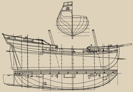
I wondered about the shipwrights who came here in the wilds of the Great Lakes region and built warship with no mold loft and no drawings. After researching these master shipwrights i realized they were trained surveyors. They built ship with only a sheet of numbers. It was called a table of offsets that converted a 2D drawing into X,Y,Z Coordinates.
One of my grandsons is a civil engineer and i showed him a drawing like the one i posted and asked can you build this without any instructions? He said "oh ya it is a 2d drawing of a 3D object no problem" You can find any point anywhere on the hull from the drawing.
 
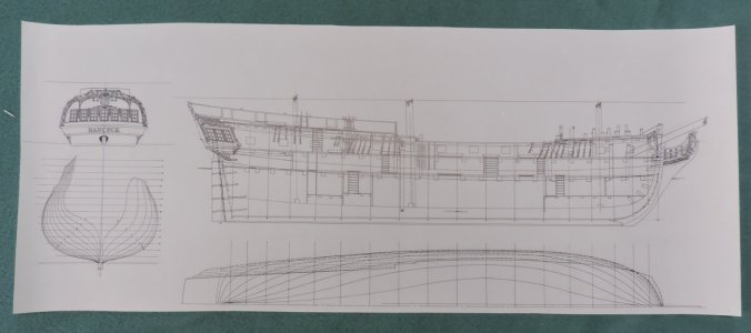
When i got interested in drawing ship plans i asked Bob Bruckshaw at one of the model club meetings on how to do it. He invited me to his studio and showed me how he did it. To my surprise he did not draw a set of modeling plans instead what he did was a series of drawing of the parts he was going to fabricate. This was done with individual tracings over a master drawing.
This was way back in time, in the 1970s BC that is before computers, so technical drawings were done on translucent drafting Vellum using a rapidograph pen on a light table.

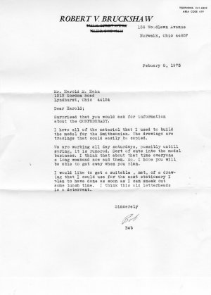
A letter from Bob to Harold on the Confederacy. Bob has the "tracings" thar he used to build his model.

img206.jpg


From Bob back to Harold he did some of his drawings on tracing paper here is the original tracing for the Kingfisher

018.JPG

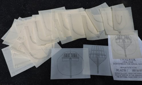
Later Harold used Vellum for his drawings

016.JPG012.JPG

Harold did the same thing Bob did and drew everything as separate patterns over a master drawing

pen ink original drawings.jpg
005.JPG

We are going to do the same thing just using different tools rather than pen and ink now it is CAD which makes the process so much easier. If you do not know CAD programs there is still the old school methods.
 
Volume #1 of the NRG’s Shop Notes includes Hahn’s drawings for one of the schooners from his dockyard diorama.
In fact Hahn’s drawings for Sir Edward Hawke, pg 96-102, including 5 pages of frame drawings! @Dave Stevens (Lumberyard) this is the intended subject for this class, yes? But you will teach us how to create the equivalent drawings I see :)
 
In fact Hahn’s drawings for Sir Edward Hawke, pg 96-102, including 5 pages of frame drawings! @Dave Stevens (Lumberyard) this is the intended subject for this class, yes? But you will teach us how to create the equivalent drawings I see :)

yes, this is the subject, but the project is based on Hahn's original drawings, for this project the Sir Edward Hawk plans are a total redrawing.

yes we will be getting into how to create a set of working drawings.
 
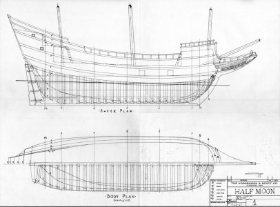
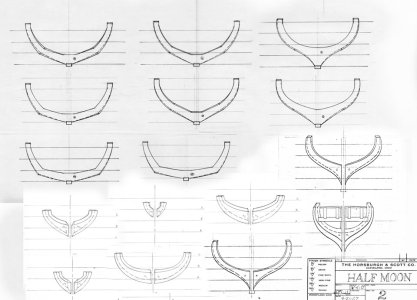
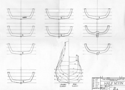
building a model is all about preplanning exactly what you want to build then figure out how to do it. take a look at the Half Moon maybe Hahns first drawing and model. It looks like a plank on frame hull but it is not really. It is a hybrid between a plank on frame on the bottom only and however he built the upper works, Harold never wrote about how he built this model.

A570.jpg


looking at the plans Harold drew he only drew the frames to the waterline

half moon 1.jpghalf moon 2.jpghalf moon 2A.jpghalf moon 3.jpg
 
Last edited:
to recap where to find plans as an example just in the Great Lakes region there are a number of maritime museums not inoculating historical societies


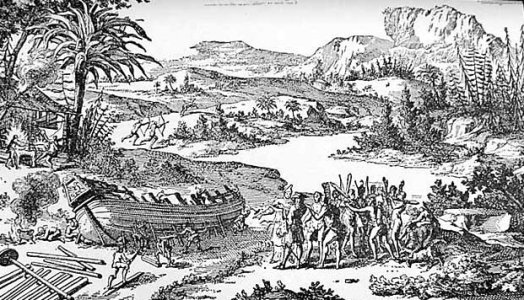
the Great lakes are rich in maritime history going back to 1679 with the Griffon

Building-le-griffon.jpg

from massive wooden warship from the war of 1812 to unique vessels like the whaleback


ec413a825803f7f9169c2e72d0418a89.jpg
 
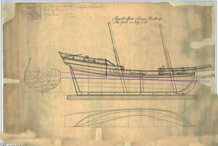
first thing is to trace the original ship plan which can be done two ways either in a CAD program or old school with drafting Vellum.
This is the tracing of the Sir Edward Hawk from the original museum plan

orig drawing.jpg

what you need is a clean sharp drawing

hawke plan.jpg
in the case of the sir Edawrd Hawk i will be tracing Hahns original drawing in order to rework Hahn's drawings into a new drawing.


hawk tracing.JPG
 
why trace the original frame drawings?

orig body plan.JPG

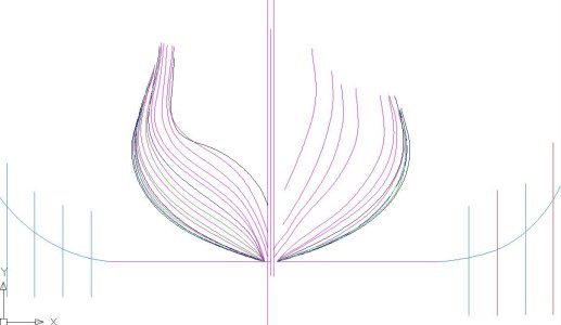
looking closer the frame lines are all tangled up

Cad6.JPGCad7.JPG

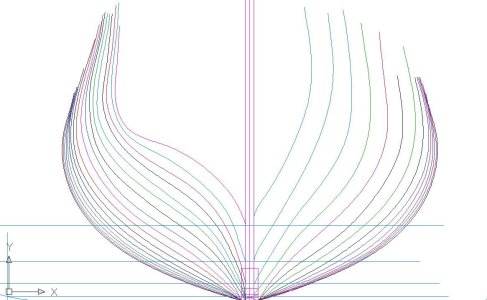
corrected bodyplan all the frame line do not overlap and the bodyplan is now a smoother shape.

Cad5.JPG
 
Thank you very much for the detailed description of the first steps.
But I immediately have a question. Why don't you a priori indicate the thickness of the material for the keel, keelson, future deadwood, frames?
Of course, I understand that all vector files are perfectly scalable. And the future scale of the model can be perfectly transformed for both 1:96 and 1:48. And the availability of materials for any newbie in ship modeling is much less than yours. Isn't it easier to immediately tie in to the thickness of the planks that I or someone else has.

By tying the model to the thickness of the planks, which are gathering dust in my nightstand, it is easier for me to start manipulating the data. In addition, the model of the approximate length of 245 mm is excessive for me, as a beginner...

Снимок экрана 2025-03-07 212611.jpg
 
Last edited:
Isn't it easier to immediately tie into the thickness of the planks that I or someone else has.

If I understand your question correctly, the answer is no. Traditionally built ships are not built to dimensioned lumber scantlings. Even where one might determine that plank thickness might be three inches, the actual thickness of the planking stock may vary for a variety of reasons, e.g., allowances for fairing and/or backing out. In any event, given the shapes of all the other timbers in a ship, a modeler, as does a full-scale shipbuilder, is always going to have to custom fit all parts. The old saying about construction tolerances used to be: "A framing carpenter works to the nearest quarter inch, a finish carpenter works to the nearest eighth inch, and a ship's carpenter works to the nearest ship!"

I believe the best approach would be for a modeler to determine the overall size of the model contemplated, then determine the scale they wish to build to. This would usually be the scale which yields a model closest in size to the size of the model they are contemplating. From there, scale scantlings would be taken up manually from scaled drawings, from a drawing in another scale using a proportional dividers, or determined mathematically from the table of offsets. As might be imagined, the odds of any stock required matching the dimensions of pre-milled stock are extremely slim. Custom milling will be costly when one might be able to source it. For this reason, although not essential, anybody considering scratch building would, IMHO, do well to acquire a band saw, disk sander, thickness sander, and micro-table saw. With these machines, which do involve a bit of an investment, one is capable of milling any stock they might require for building a model ship. If one does any amount of ship modeling, these tools quickly pay for themselves in savings over the cost of pre-milled stock. These days, the best modeling power tools available, bar none, come from Byrnes Model Machines. (http://byrnesmodelmachines.com/ - website needs updating - telephone for ordering) I believe Hahn used a Craftsman 8" table saw with a narrow kerf finishing blade to get out scale building stock back in his day.
 
Last edited:
If I understand rfuh47’s question correctly it’s about accounting for plank thickness when making your drawing. This is a pesky problem because the original hull lines drawing that you are starting with can be drawn to either the INSIDE or OUTSIDE of the planking. If you are building a POF model like Dave is you need body plan lines drawn to the vessel’s moulded or inside of the planking. This is not as simple as it sounds because in areas of curvature the correction will be more than the plank thickness. I once wrote an Excel spreadsheet to handle the trigonometry to make this cottection to offset dimensions. CAD users may be able to do this more easily. BTW: Example of an actual Table of Offsets for a real ship and resulting lines drawing drawn by me.. (Photos Below)

I also used a full sized table with a thin kerf to cut planking for the one Hahn Style POF model built many years ago. If I live long enough to finish my current project, I would cut planking, framing stock again with my full sized saw.

Whaleback Ships: One of the best pictures that I have seen as it is taken from an angle showing interesting details.

The whaleback vessel ( both barges and steamships) was invented by retired ship captain and Duluth, MN resident Alexander McDougall. A total of 44 were built including one in England. They had a major influence on design of English tramp steamships. Those interested in reading about their fascinating history (along with some drawings) is recounted in an award winning book recently published by Wayne State University Press.

Title: Whaleback Ships and the American Steel Barge Company
Author: C. Roger Pellett. (Shameless Plug By Me)

IMG_0506.jpegIMG_0519.jpeg

IMG_0519.jpeg
 
Last edited:
why trace the original frame drawings?

View attachment 505310

looking closer the frame lines are all tangled up

View attachment 505311View attachment 505312

corrected bodyplan all the frame line do not overlap and the bodyplan is now a smoother shape.

View attachment 505313
Could you provide a bit more granularity on what is involved in correcting the body plan? Also is there a standard for whether the forward or after profiles go on the left or right, or is it just a matter of preference for the draftsman?
 
I may be dead wrong, but I think the biggest obstacle to scratch building is space.
Personally, I think that that is a fallacy as many ship models were scratch built with nothing but a pocket knife and time. Which may also be a bit of an exaggeration. I do remember reading in Harold Underhill’s book that he built the Lion on a card table with only a few hand tools. That’s not to say I don’t feel blessed every time I walk into my shop/shipyard realizing that I have the tools and space that I do have. Certainly the power tools make the building process more efficient but there’s also, in my mind, a joy in shaping a part well with just a saw and some chisels, files and sandpaper. Just my two-cents.
 
I think that that is a fallacy as many ship models were scratch built with nothing but a pocket knife and time. Which may also be a bit of an exaggeration.
A small space is more of a problem if you don't live alone. There are some admirals that are not happy if there is a shipyard in the living space of an apartment or average size house. Sawdust and the occasional clutter are usually frowned upon by the spouse in charge, at least in my home:(

As far as exaggeration, maybe just a little. :) We need only look at the beautiful prisoner of war bone models done with tools that did not run on electricity.

Allan
 
I have Ewart C. Freeston's book Prisoner of War Ship Models. In it you can clearly see just what can be accomplished with a tiny bit of space, a minimum of tools and supplies, and a whole lot of time. I think for many of us time really is the limiting factor. I have a vision of some cosmic high-order polynomial in which the capacity to produce a model is a function of space available, time available, and money available.
 
To add to Dave’s post above:
When I learned to make lines drawings, they were first made with pencil and ordinary drawing paper. The process by its nature requires many erasures as lines in the various views are juggled to match. Once the pencil drawing was completed it then had to be traced in ink on to vellum. State of the art then was a double nib drawing pen or if one could spend the money an a German Rapidograph drafting pen. Ink blobs were common and erasing the ink from the vellum impossible.

Fortunately there are now items that make hand drawing ships lines fun:
Frosted Mylar drafting film.
Electric Eraser
Inexpensive disposable felt tipped drafting pens.

Like in days past, I usually trace lines drawings in ink after making a pencil drawing. Both are made on Mylar. Unlike vellum, ink erases easily from Mylar. For me much more pleasant than sitting at a computer.

Roger
 
OK ALL I WILL TRY TO MAKE IT SHORT OK JUST FINISHED A STINT IN HOSPITAL 25 DAYS IF ANYONE ITERESTED IN USA HEALTH CARE GOOD AND TERRIBLE YOU CAN CONTACT ME PM OR OPEN FORUM NOW A DIFFERENT AND YES SCARY THINGS HAD TO RELOCATE TO A NURSES FACILITY PERMANATLY 6 PATIENE ABOUT 15 AIDES, NURSES, CARE GIVERS DR SPECILIST AS NEEDED I HAVE KNOW DAVE STEVENS FOR AT LEAST 20 YEARS WE HE AND I HAVE FOUGHT THE SYSTEMS BOTH WITH AQND WITHOUT IN ALL OUR CONVERSATIONS I KNOW AND I AM PRETTY SURE DAVE KNOWS ALSO IT IS FORWARDING THE HOBBY OK DAVE THE JUNK YARD DOG WE WORK THIS ON ON THE SAME. THIS NOT ONLY A HYOBBY NOW BUT PERMANENT HERE, I HAVE AQ DIFFERENT MIND SET ABOUT MODELIN I HAVE TO TRY TO KEEP THE MODELS SIMPLE I HAVE WAS AND AM INTERESTED GREATLY IN RESEARH LIKE CHARLIE T WALDAMERE ETC MAYBE I CAN LEARN THE WHYS AND HOW OK SO I NEED SOMETHING THAT DAVE IS DOING DO NOT LET NYONETHINK IT WILL BE EASY IT WILL NOT MY PROBEM WITH DYSLEXA IS STILL THERE NOT BAD BUT CAN CAUSE SOME PROBLEMS I HOPE TO JESUS WE CAN MAKE IT ALL COUNT DAVE TO YOU HIT ME BACK YOUR COMENTS PLEASE. GOD BLESS STAY SAFE YOU EV AND ALL DON
 
If I understand rfuh47’s question correctly it’s about accounting for plank thickness when making your drawing. This is a pesky problem because the original hull lines drawing that you are starting with can be drawn to either the INSIDE or OUTSIDE of the planking. If you are building a POF model like Dave is you need body plan lines drawn to the vessel’s moulded or inside of the planking.

hull lines are usually drawn to the inside of the planking or drawn to the face of the frames. This is done because the planking on a hull is not always the same thickness. Bottom planks are thicker than the side planking. Also war ship have what is called thick stuff which is a run of planking above and sometimes below the main wales.
 
Back
Top