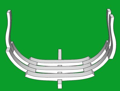
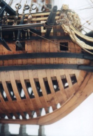
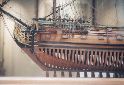
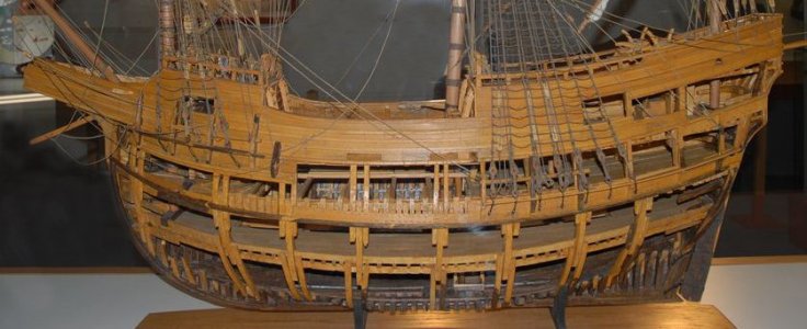
School for model ship building

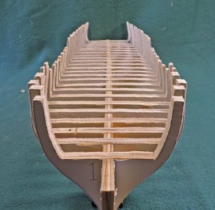
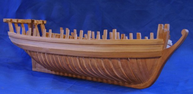
so far the discussion has been around scratch building a plank on frame hull. But scratch building is not limited to plank on frame you can design and build a hull using bulkheads or what is called the bread-and-butter method which is building from lifts.
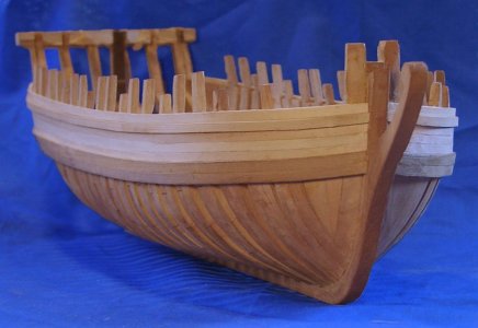
for now it is back to framing. The problem with framing a hull is keeping all the framing the correct place.

first issue is to make sure the frames are square to the keel, The problem is you only have that little notch over the keel and a frame can move quite a bit.
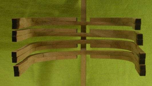
square frames.jpg


a solution to squaring up the frames as you install them is to use a backing piece. Start with the midship frame and work your way to the bow and stern.
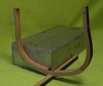
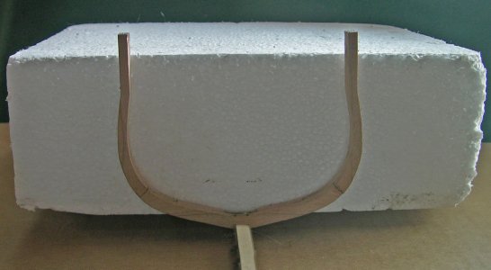
block frame.jpgfoam frame.jpg

by using a square backing block you also are keeping the frames from leaning, the frame on the left is leaning in.
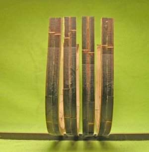
leaning frame.jpg

another way to prevent frames from leaning fore and aft is to use blocks between the frames. Once you square up the mid frame the next frame is located in the keel notch and blocks used at the top. I learned the hard way this is not a fool proof method because if all the space blocks are ever so slightly different thicknesses that slight error adds up and the entire structure will lean.
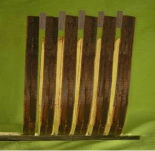
spacer slant.jpg

Frames will move side to side and back to front and it is a task to keep everything in line.
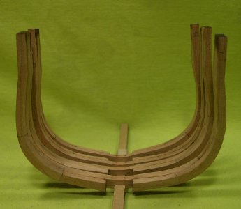
tilt frame side.jpg

a problem reported by builders using the Hahn jig method found themselves still having a problem keeping the frames level side to side

level frame.jpg

The problem happens when the extensions are not finished exactly the same, the top extension sits in the jig which located the height of the frame. Hahn used a jig to insure each frame fit tight to the top of the keel and the top of the extensions sat against the jig
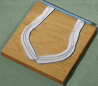
method7.jpg

Harold's use of a jig solves the problem of locating the frames and holding the in place.
 
Last edited:
This is why I included Alan Yedlinsky's Scantlings of the Royal Navy book on my "reading list." It's all there in readily accessible spread sheet format! It's a huge research time saver.

This is a great reference for the size and spacing for hull framing but it is only for a certain period in ship building as the establishments did change over time. Also the British establishments do not apply to all hull framing all the time.
For example, an older method used to frame up a hull

frameshape1C.jpgA45.jpgA51.jpgSan-Juan.jpg


the there is the stepping of frames

tapered frames2.jpg
tapered frames1.jpg
tiered framing.jpg

the room and space where the space between frames are equal to the sided demission of the frames.

single framing.jpg

and the bends and filler framing

frameshape sf.jpg

sister framing

frameshape2C.jpg
 
In model building we make all the frames the exact same size and evenly spaced. That is not the case in real ship building it depends on the the type of ship. Here is the frame spacing for the Eagle built on the lakes. The frame spacing varied from 5 to 2 inch space

Eagle framing section.jpg

Steam ships had solid floors under the engine the spacing is different all along the keel


pleasure2.jpg
pleasure.jpg

in some cases, framing was also so close together the hull was a solid wall of framing timber

princess charlotte closeup.jpg

some hulls used strapping

strapping 1B.jpgstrapping1A.jpg
argo strap1.jpgargo strapping 2.jpg
 
Last edited:
as i was saying you don't have to frame up a hull if you intend on planking it. A fully planked hull with all the plank runs following the hull shape is a really pretty thing to look at.


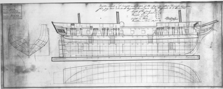
I am using the princess Charlotte for this lesson in setting up a plank on bulkhead hull
go here to read all about the Princess Charlotte


princess charlotte lr.jpg


starting with the tracing

tracing.JPG

we need the center profile it runs under the deck at the top and along the rabbit line at the stem, keel and stern post. The lower blue line is the top of the bulkhead slit.


profile piece01.jpg

next set up the bulkhead locations. I placed them alongside the gun ports

bulkheads01.jpg
 
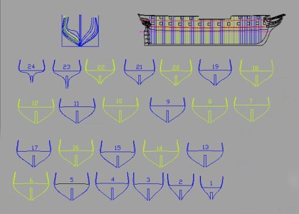
for the bulkheads i traced the station lines

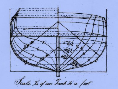
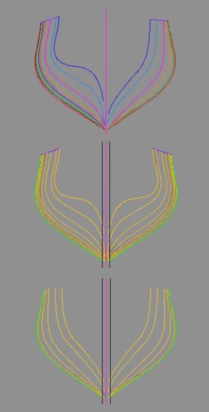
bodyplan1.jpg

as i did with adding frames it is the same for adding bulkheads. If your doing this by hand blow up the original bodyplan it is easier to draw the line between the stations.

bodyplan2.jpg

when you have all the bulkhead lines drawn i split the bodyplan from midship forward and aft. Then mirrored each side to complete the shape of a bulkhead

bulkhead1.jpg

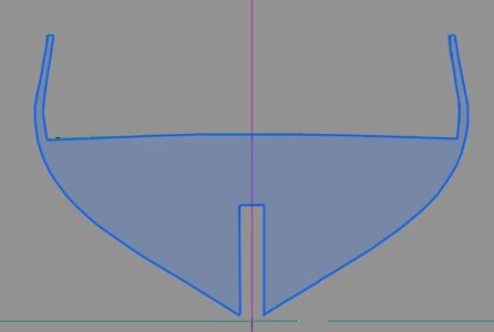
When the bodyplan is finished you line it up with the profile. The 3 blue lines are the rabbit at the bottom dark blue line is the top of the bulkhead slots then the deck and the top of the frame, You want to make sure the slots in the bulkheads match up with the profile slots. the deck is nor flat so the height changes from bulkhead to bulkhead.

bulkhead2.jpg

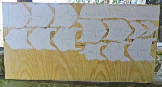
you are dragging each bulkhead shape from the bodyplan and shaping the top and adding the deck

bulkhead3.jpg

finally, you have all the bulkheads

bulkhead4.jpg

this has been done in kits since the 1950s without a computer aided program CAD so yes you can do this by hand no problem.
 
Last edited:
Hi Dave,

I am enjoying the information and gaining a great deal of useful knowledge. A long time ago I was a draftsman and I designed a 42' racing sailboat. At that time it was all by hand. Now I don't have the equipment to draft by hand. What CAD program do you use or suggest. If I missed your suggestion, I apologize.

Bill
 
I am enjoying the information and gaining a great deal of useful knowledge. A long time ago I was a draftsman and I designed a 42' racing sailboat. At that time it was all by hand. Now I don't have the equipment to draft by hand. What CAD program do you use or suggest. If I missed your suggestion, I apologize.

i am using a very old version of AutoCad 2004. it has everything needed to draw. I also have Turbo CAD and Fusion 360. There is a discussion on the forum about drawing programs. Actually, programs like Adobe Illustrator.

i use drafting programs because i can convert the files to 3D CNC or print files and for building 3D models.
To build a hull you can do everything in Photoshop with scans and printing on Vellum. in my personal opinion if you can build the model you surely must be able to do a basic drawing, don't let drawing spook you, you do not need a computer and drawing programs to do this.
 
This is why I included Alan Yedlinsky's Scantlings of the Royal Navy book on my "reading list." It's all there in readily accessible spread sheet format! It's a huge research time saver.

This is a great reference for the size and spacing for hull framing but it is only for a certain period in ship building as the establishments did change over time. Also the British establishments do not apply to all hull framing all the time.
For example, an older method used to frame up a hull
Quite so. Perhaps I should have been even more specific. The books covers Admiralty data between 1715 and 1805. In terms of any information on the actual construction of British sailing warships, that's the best of what we've got and even then there were many deviations from the norms. Merchant vessels would be likely more lightly built, but that's only a presumption. We'd have to look to the modern maritime archaeologists to continue to add to our store of knowledge on construction details other than the Royal Navy's. That said, I'd hazard a guess that for reasons I don't completely understand, there are more ship models built of Royal Navy ships of the subject period than anything else these days. :)
 
“Solid, bread and butter” or more correctly laminated hulls are also a viable option for building ship models. I personally get a lot of enjoyment sculpting these hulls. It is the way that Naval Architects often designed ships years ago. Nathaniel Herreshoff designed his yachts this way. He had instrument maker Brown and Sharpe design and build a machine for taking off data to be sent to the mould loft. He did not draw lines drawings.

I make my models by carving two half models.

Unfortunately, very little is known about early American Framing practices as ships were built in local yards, and of course records were lost in the Washington, DC 1815 fire. It may seem strange but more is known about framing of Great Lakes Vessels. Cold fresh water and lack of shipworms have protected them. Unfortunately, zebra and quagga mussels are covering up many.

Chapelle writes that British Admiralty officials often complained about lightly framed captured American vessels, and when they duplicated their lines, they often spoiled the vessel’s performance with heavy scantlings.

Roger
 
Last edited:
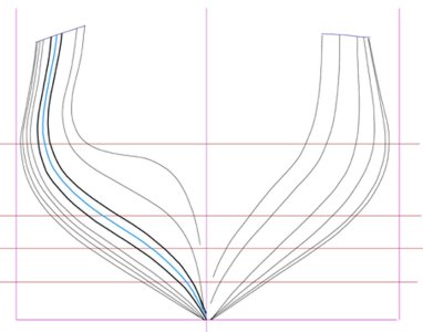
“Solid, bread and butter” or more correctly laminated hulls are also a viable option for building ship models.

"Bread and butter" laminated hulls, solid or hollowed out, are the easiest to build of all in my opinion. All that needs be done is to trace the waterlines (and perhaps add a few on your drawing board if you wish and then cut a couple of boards the thickness of the distance between the waterlines to the waterline, leaving one straight edge of the boards as the centerline of the vessel. If you cut two boards together, half and half, you'll have a matched pair when their straight edges are placed together. When all the waterlines are stacked up and it's all glued together, all you have to do is "knock off the corners" of the steps between the stacked board edges and sand the curved shapes fair with a batten with some sandpaper on it. The inside corners define the shape of the hull as you go.
 
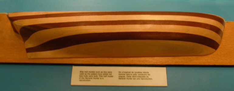
making a lift hull can be done as a finished decorative piece or used to build a solid hull. A member of the club years ago would build small solid hulls using the left method. Back in the day when piano keys were made of ivory Charley would salvage the ivory and plank his solid hull . A solid hull makes a good foundation for planking.

you can use different colored wood for each lift


half hull.jpg

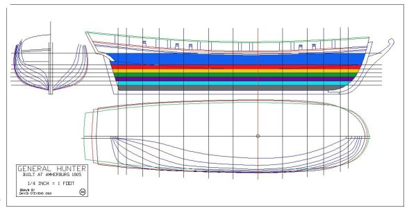
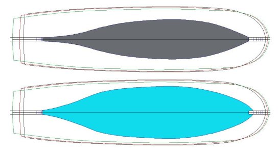
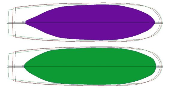
here is the basic idea for building a lift hull the thickness of the lift is shown on the profile by horizonal lines the sheer drawing give you the shape of each lift. Each lift is cut out and glued and stacked together. sometimes small wood screws are used so the lifts do not come apart.
If the hull is used to draw out the hull lines the lifts are made to come apart so they can be traced


lift1.JPGlift2.JPGlift3.JPGlift4.JPGlift5.JPG
 
drawing all the frame with bevel lines is a tedious and time-consuming process. Mistakes are very common when drafting frames and you do not find the errors until you assemble the hull. There is a way to skip the drawing and use a vertical lift method. No doubt there is blow back from those who use the traditional methods of drafting a hull. You can not do that because that is not how it is done.

bodyplan1.jpg


starting with a basic bodyplan what i am doing is taking the thickness of a frame (sided dimension)

frame block.jpg

and cutting out the station lines from the bodyplan the space is added to the pieces.

pattern 3.jpg

because there are more frames than station lines actually there are two frames between each station line i am going to fill the gap

pattern 4.jpg

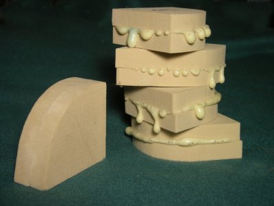
each filler piece is glued up from 2 pieces the thickness of the frames plus the space i used an expanding glue which was not a good idea

glued blocks.jpg

midshipthere is little difference in the shape of the blocks but they will step down as the approach the bow and stern

carved block2.jpgcarved block3.jpg

the blocks are now glued up to form the hull
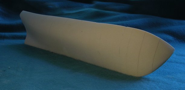
The hull is made from a dense foam board used for sculpting. Do not sand the hull in doors. The static will cause the dust to cling to everything, actually it is not a dust it is a very fine grit.

assembled hull blocks.jpg

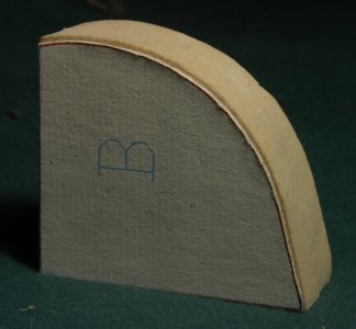
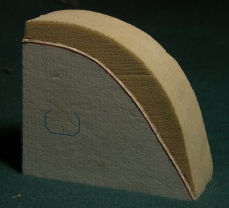
the finished hull

finished hull 1.jpgfinished hull 2.jpg

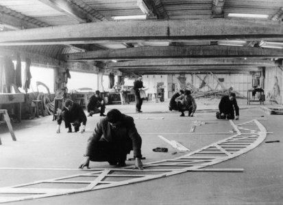
traditionally this would be a builders 1/2 hull and measurements called offsets would be taken off the hull and sent to the mold loft

d.jpgOld-Lofting-Template.jpg

i am not building a real ship here i am building a model so i substituted the mold loft floor for a band saw and sliced the hull like a loaf of bread

finished hull 3.jpg


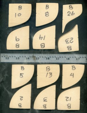
took all the slices and scanned them now i have the outside of all the frames and bevels

scan sample.jpg
 
Once toy have a corrected bodyplan you can pull out one frame shape at a time and draw the inner spare of the frame called molded size and shape The is a long and tedious job both by hand and in CAD.

step0.JPG


Start with making a copy of the frame in CAD you can select the copied line and use it like a template or by hand print out the frame. You do not need both sides of the frame drawing so cut it in half down the centerline.

What you want to do is cut out the frame shape and you will be usings it a template to trace.

template.jpg


.
 
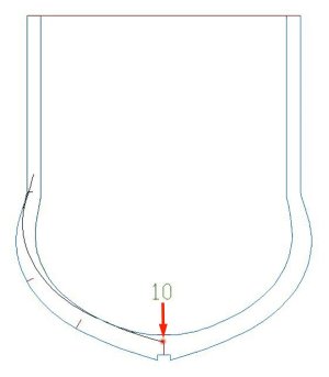
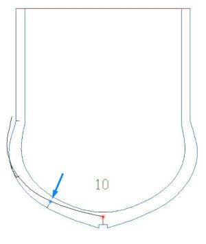
before moving on those little short lines are the points at the ends of the futtocks which are the frame sections. The length is important because it is defining the shape of the inside of the frame. The placement of the lines is hit or miss as long at you have the general location of the floor heads, and futtocks.
Some builders get into the exact structure of the frames keeping close tolerances but that is at a whole different level of building, more like model engineering.


step1.JPG


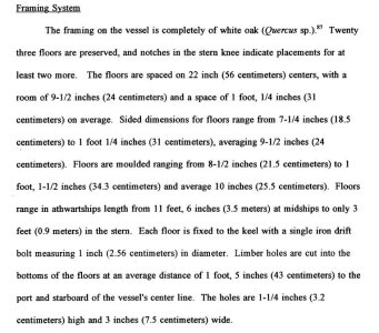
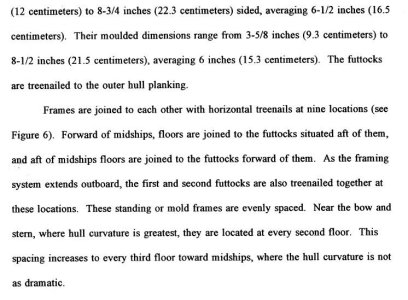
the lengths you will find in ship contracts or the establishments or archaeological records like the following.

rpw1.JPGrpw2.JPGrpw3.JPG

 
drawing the inside shape of a frame by hand and with CAD

take the template or select and copy the outside shape and place the end on the top of the line at the red dot.

step2.JPG

rotate the cardboard template or select the line in CAD and rotate it so it matches up with the second line the blue dot


step3.JPG

trace the template from the red dot to the blue dot, i CAD break the line at the blue dot

step4.JPG

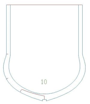
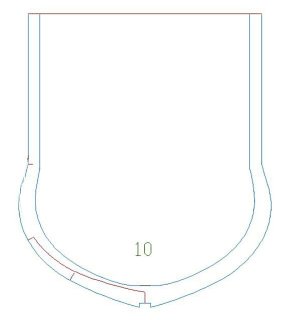
take the cardboard template and rotate it at the blue dot until it matches up with the next line green dot. In CAD where you broke the line select the end point and rotate the line to meet the green dot line

step5.JPG

trace the edge of the template to the green dot. in CAD break the line at the green dot

step6.JPG

sometimes the inner line does not give you the right taper so you have to fiddle with getting it in the proper place. with the last line in this case has to be rotated from the top to the bottom rather that what was done so far which was from the bottom to the top

step7.JPG

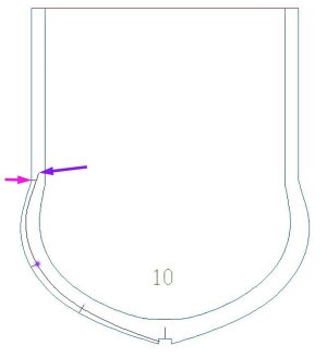
you have to adjust the top because if you rotate the template or the line in CAD you end up with a narrow section. Move the end of top line purple to the magenta line

step8A.JPG

now rotate the top to match up at the purple dot and trace the template

step8.JPG

you now have a nice inside frame line with the correct taper from the floor to the cap rail.

step9.JPG

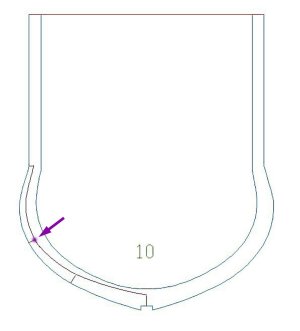
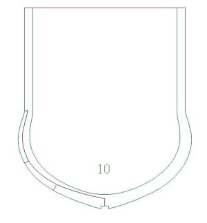
mirror the left side to the right side to complete the frame. Notice the frame just drawn does not look like Hahn's original frame drawing. We will get into that later.

step10.JPG
 
Last edited:
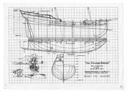
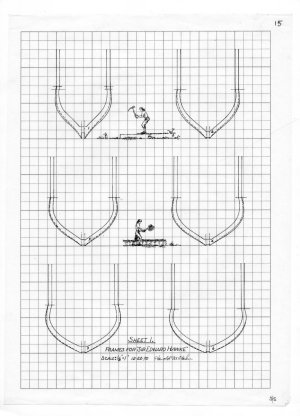
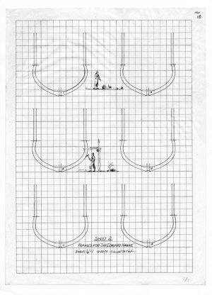
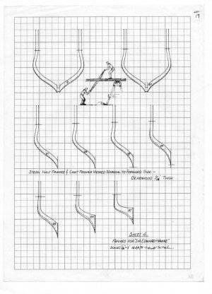
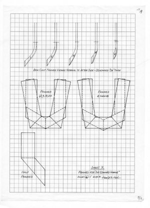
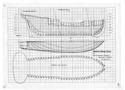
Harold Hahn never did a final drawing on the Sir Edward Hawk or offered a set of plans. What we do have to work with is his working drawings he used in an article on building a plank on frame model.

img331.jpgimg332.jpgimg333.jpgimg334.jpgimg335.jpgimg336.jpgimg337.jpg

The first step is to scan the original drawings as a JPEG file then using AutoCAD 2004 bring in the JPEG files to trace

Cad2A.jpg
 
Back
Top