Soleil Royal by Heller - an Extensive Modification and Partial Scratch-Build by Hubac’s Historian

Hello again!

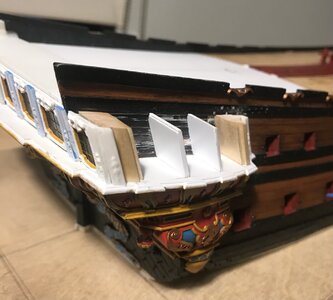
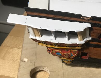
I was surprised to discover that my initial fairing to the shape of the hull, for these lower finishing pieces, was only approximate.

I was sanding them along the curving arc of the lower main wales, but not accounting for their actual rake in the horizontal plane. It was also only possible, initially, to guess at what the connecting angle would be with the transitional moulding above.

When I first offered these up to the hull, after securing the section above, I found that there was significant daylight in the middle of the piece, and the top angle was all wrong.

It took a fair amount of careful contour sanding and re-checking, but eventually I got the pieces flush up to the hull, fore and aft, and a closed joint at top.

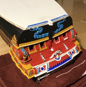
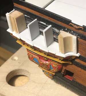
Here you can see the changing tumblehome as reflected upon these inner surfaces:
View attachment 200387
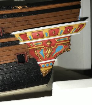
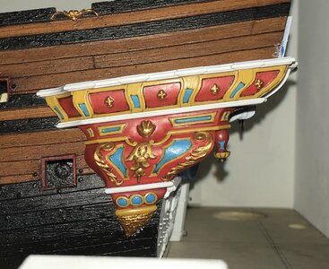
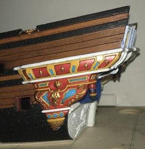
One mistake I made was painting these before final fitting. All of that handling burnished through much of the gold. I also found that, while ordinarily sure-handed, I kept dropping these delicate pointed things on the floor. Lots of swearing! My kids wrote a song in my honor for dad’s hobby-time: “Oh EFF!!, I dropped my model... Oh EFF!!, the paint is scuffed!”

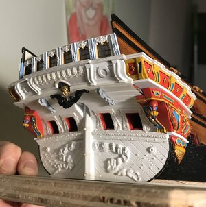
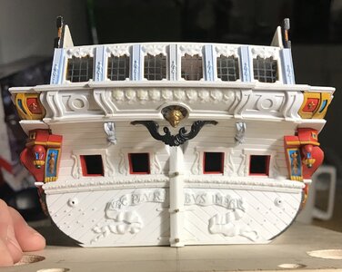
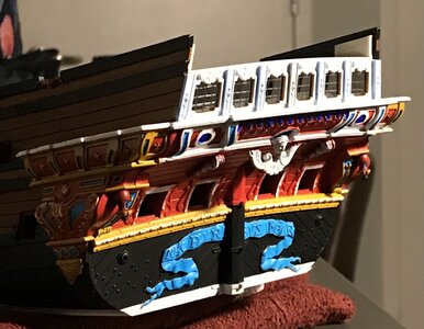
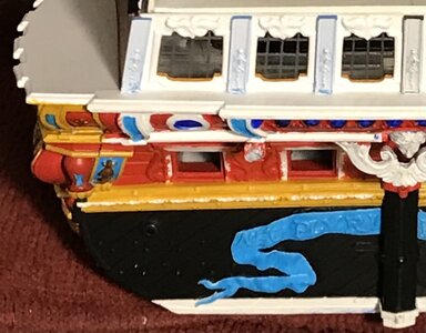
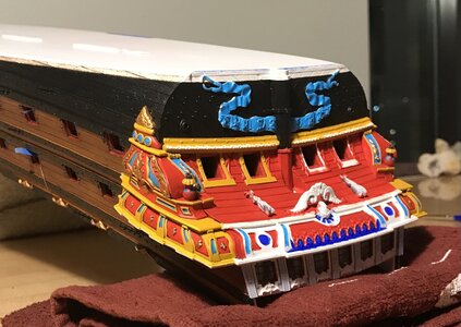
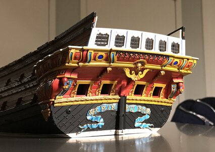
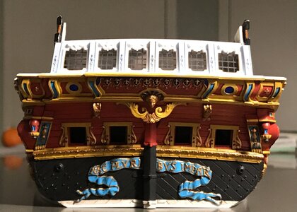
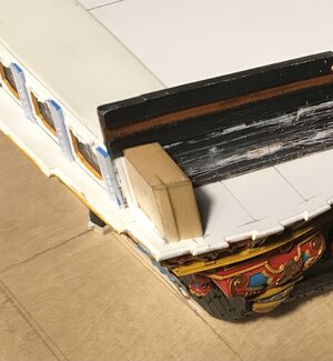
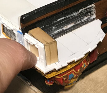
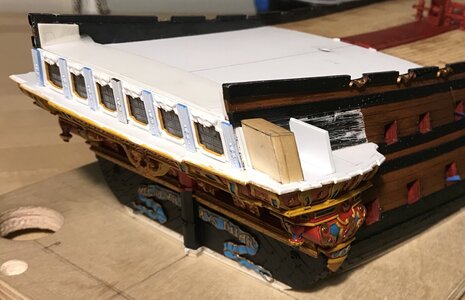
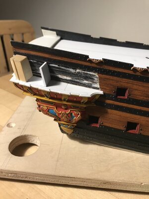
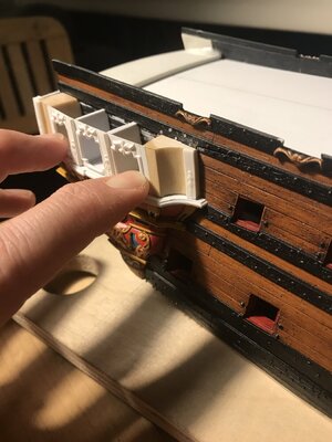
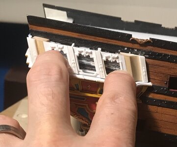
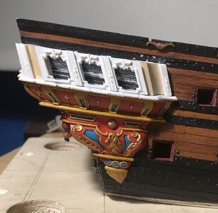
Anyway, after fitting and retouching, I was finally able to secure them in place:
View attachment 200384
View attachment 200386
View attachment 200382
View attachment 200383View attachment 200383
View attachment 200381
Now, while I could not be happier with how this is progressing, I do sometimes think it is important to talk about some of the things this model IS NOT, even though it aspires to be them.

While I’m pretty sure that I have an accurate read on the shaping of the active seats of ease, I am less certain about the lower finishing.

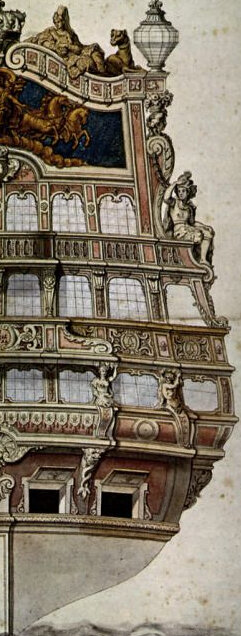
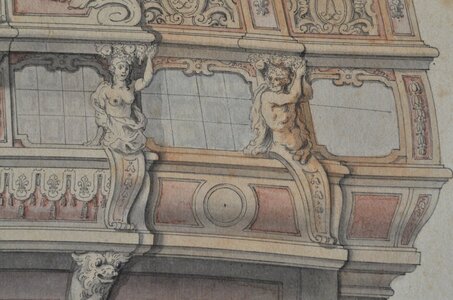
In this port quarter drawing of La Royal Therese, one can see the seats of ease section pretty clearly:
View attachment 200393
There isn’t really a lower finishing beneath, so it fairs back pretty closely to the hull. Nevertheless, I think I’ve captured the shape and weight of this section pretty well.

Here is another example in Le Terrible:
View attachment 200392

I do wonder, though, whether I’ve left the aft end of the lower finishing as too full. While I think I have the general contours correct, a part of me thinks that the aft end should probably round back more closely to the hull. I am not going to change it, but it is something to keep in mind for anyone else attempting to model these early QGs from pictures, alone.

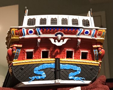
The other issue to note is the exaggerated overhang of my stern counter:
View attachment 200380
As I’ve discussed before, this is a byproduct of my approach for including the round-up of the transom; in a tapering arc, I pared back the transom edge of the hull, towards the waterline, so that my stern post would not be positioned too far aft into the stern counter. This is a difficult thing to explain, and my whole line of reasoning may have been flawed, there, but it was an educated guess, at the time.

The result was a very rakish stern counter, which I find aesthetically pleasing, but it is not strictly accurate for the period.

One look at Tanneron’s models of Le Brillant and L’Agreable confirm a flatter, more vertical counter:
View attachment 200397
View attachment 200396
View attachment 200395
Lemineur’s monograph for the SP re-enforces this notion. It is notable, also, how Le Brillant’s lower finishing is relatively less bombastic than mine, and fairs much more closely with the hull.

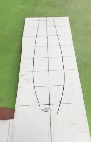
Anyway, making this model in the manner in which I am is sometimes a guessing game. One particular benefit of this QG is that it extends beyond the line of the transom, and obscures the exaggeration. I will have to make a pair of wrapping corbels that finish this detail of the model. Here are the pattern tracings I have made for this purpose:
View attachment 200378

Anyway, EFFIT! as this moderately old man is wont to say. Taken in its entirety, these small architectural variances should not be too glaring:
View attachment 200379
View attachment 200388
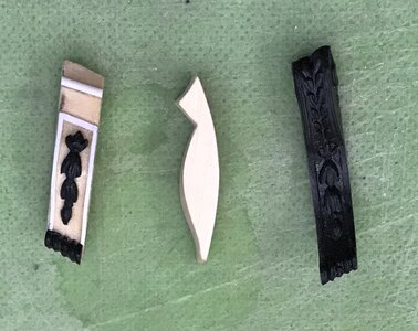
So, I’m just finishing up the low finial of the lower finishing. I will wait to paint these until after final fitting:
View attachment 200390
View attachment 200389

Once those are in place, I can concentrate on making the window section above.

Now that I know the North East Joint Clubs meeting is slated for October, I will try to get a certain amount of work done. I would like to get the upper bulwarks up and painted, the structure of the upper stern framed and planked, the quarter deck installed, and perhaps make a start on the galley stove.

Given my pace, so far, this is ambitious, but not altogether impossible. When I last showed the thing, two years ago, it was merely a collection of un-assembled parts. However far I get, it will be a vast improvement.

As ever, thank you for stopping by, and for your likes and comments. Happy Holidays!
View attachment 200385

Amazing work once again Marc,

I would think the shape of the stern is very subjective and without good accurate drawings these things are really only a best educated guess, an interpretation of someone else's art work.

Cheers,
Stephen.
 
Thank you, Stephen! Personally, I think all ship modeling is, more or less, an art of interpretation.

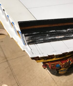
So, the low finials are now painted and in-place. You can see, below, the 3/16" spacing (18", full size) between the last gunport of the lower deck and the quarter gallery. This resulted from filling-in and moving the port forward 1/4" from its stock location, at the start of the build. Here are a few less than stellar pics of that:
0703184A-5F81-4A59-8CDA-CC39B18AA894.jpeg
7217657E-28AF-4E71-BB31-405474760B6D.jpeg
77A47683-17B3-42B1-AFB8-DBB1CD851408.jpeg
There will be some re-touching to do, but I am very pleased with how this all resolved.

The past few days, I’ve been making the wrapping corbels. The ones the kit provides are perfectly lovely, and I had hoped to adapt them to the new shape of the lower finishing. It turns out, though, that the new shape was too radical a departure, and the available space for them is now shorter.

All of that considered, though, I still found it to be an efficient process to extract the ornamental scrolls and bell-flowers. The new corbels are shaped like this:
CE8A61FF-5125-4B78-B469-3E8E0A32EF3C.jpeg
As was true for the QG sections, most of the work, here, was scribing these corbels to the compound curves of both the counter and the lower finishing. Extracting and glueing-on the trim was easy.

I can’t quite remember who suggested it - maybe T_C (MSW) - but painting these soft “lime” parts with CA is really the best approach. The wood essentially becomes case-hardened, and after a light sanding with 220, the grain fully disappears under paint. This is ideal, as I did not want the tell-tale signs of mixed-media.

I’ll prime these tonight and paint them before installing on the model.

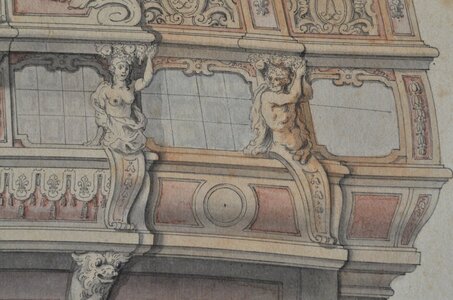
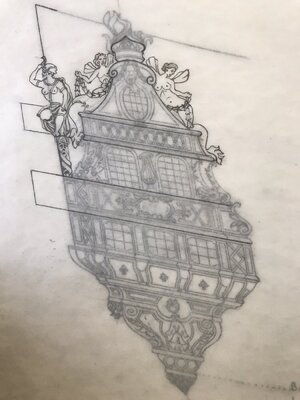
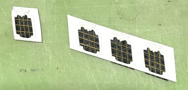
I’ve been strategizing how best to represent the false windows of the QG. I have an idea that picks up on the individual shading of panes on Berain’s drawing.
F00B6DCB-9848-4223-BBAE-A78AC48BEA50.jpeg
I have at least one scrapped window to experiment with. We shall see. I will begin drafting and making these window frames in the next few days.

Thank you for looking in! More to follow.
 
Last edited:
‘Just a quick update. Corbels are painted and in-place. Yes, I will fill and fair that joint at the top :
C9A98536-E6CD-4AE2-B761-16B42EE79118.jpeg
D1AB3CDF-8C48-4BC7-A073-7C8535188458.jpeg
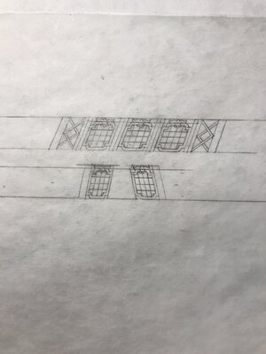
I have the port side and stern quarter windows drafted:
A4ABC1B4-46B6-4418-AF75-3F3C529FA6DF.jpeg
One of the problems/complaints, concerning the Berain/Vary drawing is the sometimes confounding inconsistencies between the irrefutable Berain stern drawing and the quarter drawing.

Because the, now, concrete reference points of the model enable me to make reliable drawings for this next phase of the build, I decided to address these inconsistencies.

The reality of the kit meant that the actual space available for these windows is taller than what I initially drew:
388F34BB-8CDA-45BE-B25D-8FA5F3CAA8C1.jpeg
One way to effectively deal with that real height discrepancy, while also helping with consistency, was to include the same window ornament, along the top stile, as seen on the stern.

The fact that I have reduced these QG windows, in number, from 5 to 3 helps with the overall width to height ratio. This is different from what Berain/Vary drew, but more consistent with better understood examples of the time (SP, 1693), while also paying respect to the hard realities of the kit.

Happy New Year, SOS!!
 
‘Just a quick update. Corbels are painted and in-place. Yes, I will fill and fair that joint at the top :
View attachment 203039
View attachment 203040
I have the port side and stern quarter windows drafted:
View attachment 203038
One of the problems/complaints, concerning the Berain/Vary drawing is the sometimes confounding inconsistencies between the irrefutable Berain stern drawing and the quarter drawing.

Because the, now, concrete reference points of the model enable me to make reliable drawings for this next phase of the build, I decided to address these inconsistencies.

The reality of the kit meant that the actual space available for these windows is taller than what I initially drew:
View attachment 203041
One way to effectively deal with that real height discrepancy, while also helping with consistency, was to include the same window ornament, along the top stile, as seen on the stern.

The fact that I have reduced these QG windows, in number, from 5 to 3 helps with the overall width to height ratio. This is different from what Berain/Vary drew, but more consistent with better understood examples of the time (SP, 1693), while also paying respect to the hard realities of the kit.

Happy New Year, SOS!!
Happy New Year to you as well Marc,

And I am looking forward to more of your beautiful work throughout the coming year.

Cheers,
Stephen.
 
I have to say that, while the making of window frames is labor intensive, it is an enjoyable process.

One cause for satisfaction is that the original drawing is quite a mess, in this section:
33292191-CBB2-417C-AC95-D144959DC1CA.jpeg
The reduction of windows from five to three just really de-clutters the whole design. Also, ensuring that the top and bottom rails of the windows are parallel improve the overall sense of balance.
A brief montage:
004BB29C-710D-454E-94E9-A473E57A7F66.jpeg
ECDB42E5-D5D9-4CEE-AA75-F6F1CC0A36E0.jpeg
This is one approximate idea for doing a stylized false window. It isn’t exactly what I had in mind, but it is an idea worth playing around with a little. I’ll make some extra panes to experiment with a few different looks.
7987A1F6-F1E3-44D0-8B50-05733E4FE5E0.jpeg
6B9C50A8-34B7-48B1-B413-F52027E0A8B5.jpeg
48B05656-47F4-47E6-8A1B-78D1A6FB702A.jpeg
By including the top-rail ornament, I ensure that there is consistency with the corresponding stern windows. If I had made simple frames, without these ornaments, the windows would appear too tall. Another nice thing is that, for a change, I have a really clear idea of what the underlying structure of these windows will be. Constructing them should be relatively straight-forward. Anyway, it is a work in-process.

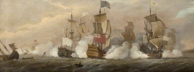
I tried to get a decent zoom into this portrait of the Battle of Barfleur by Peter Monamy:
6F9E833A-6D0F-435B-91F7-919B39D3024E.jpeg
The well-documented stern of HMS Britannia is easily recognizable. There is a strong likelihood that the French ship firing on her from the starboard broadside is Soleil Royal.
ACA8B6A4-14A4-4465-B16D-5363983DBEDE.jpeg
Like all potentially credible portraits of SR (Monamy is in the upper echelon of period marine artists), these thumbs are too small to read for detail. This portrait may still exist in the Glasgow collection, though. I will have to send an inquiry.

’Twas a dark day for America, yesterday. Hopefully, more sane days are on their way.

Thank you for your likes, comments and looking in!
 
Thank you, Gentlemen, for your kind words and likes, and to everyone who stops by now and again.

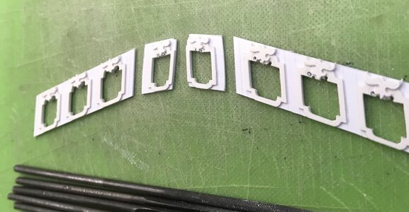
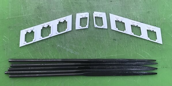
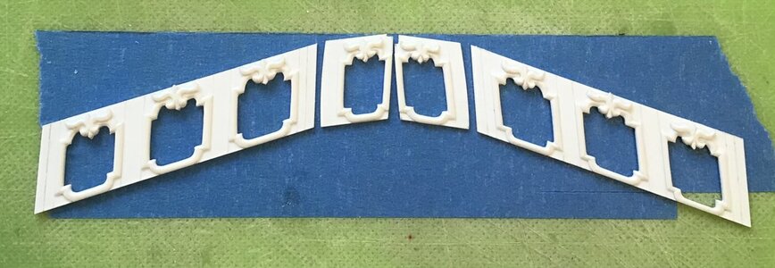
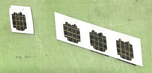
I have completed the quarter gallery window frames:
58BA7D6E-E261-4E49-B5A2-E50A8EDAC496.jpeg

I, then, spent quite a lot of time deliberating how I wanted to represent the fact that these windows were likely all superficial. There were probably removable panels, within the false windows, that could serve as either additional gun ports, or as ventilation, but they were not glazed windows, as on the stern.

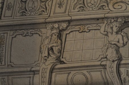
On the following section of the original stern drawing, Berain indicates glass panes with square shadow boxes, within the leaded cames:
55E97D48-BADD-4B6A-B9FA-D16B884667D1.jpeg

All contemporary evidence suggests that the six windows within the quarter galleries were actual windows. This drawing device gave me an idea for a stylized, false window.

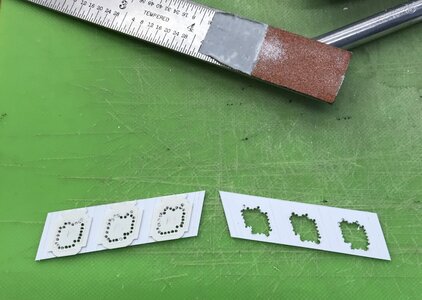
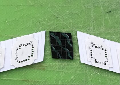
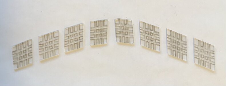
I used a semi-opaque grey enamel wash to paint-in those shadows, within my engraved lines:
0093FCDC-6E0A-462F-9876-A7367B7981AB.jpeg

After spraying the backs of the panes flat-black, the shadows show-up as a subtle indication of individual glass panes:
6F85BF70-DBE3-41A6-BD02-E1695882545C.jpeg
I decided to use yellow ocher for the cames, in order to draw attention to the fact that these false windows are different from the clear panes seen on the stern and quarter deck, admiral’s cabin. The two stylized windows on the main deck level of the QGs will also be painted yellow and black.

So, before I can actually get busy constructing these windows, I must first finish painting the lower stern. Let me tell you - I have made quite a difficult job for myself, here.

The overhang of the stern counter is such that finding a comfortable angle at which to reach the furthest corners and cut a straight line has proven to be the most difficult aspect of this build so far. The hull is relatively large and so full of extra structural plastic that it is quite heavy and awkward to move around and hold steady as you paint your lines. Even just brush-priming the surface so that it was reasonably tidy was very time-consuming.

Nevertheless, if the paint work is not impeccable, this has all been a waste of time. This is obviously a work in progress, and the colors are very stark and garish without the eventual walnut ink wash, but these pics give a stronger sense for where this is all headed:
B39A05B2-DF39-4542-AC98-899779245914.jpeg
4C360E02-8F90-40DF-A6D2-61B7EF8894F9.jpeg
I didn’t really need to paint the top and bottom edges of the transom moulding, however, doing so conveys the full depth of its scantling:
CFA6E55C-5030-471A-B291-073BCF156B9F.jpeg
There will be small touch-ups, yet, but the results were worth the extra time.

Last night, I completed all of the transitional mouldings of the QGs, and started cutting-in the chase ports:
F883679C-A28A-4049-AEC2-9142D15BD4BF.jpeg
7E2B8519-4E98-4206-835A-8DE5B3348446.jpeg

As I’ve mentioned before, the use of ultra-marine will be relatively sparing. I was going to leave the inset circles red, but I realized that there are oval monogram cartouches on the balcony railing above that will also be painted ultra-marine, thus balancing the composition. All will become clearer as we go.

Today, I will re-pattern the transitional moulding plate that sits atop the QG windows, and serves as the base for the wrapping balcony. It is identical in profile and depth to the denticulated transitional moulding beneath the windows. The only difference is that this platform will extend aft, four scale feet in order to wrap to the stern balcony. I am kicking myself for not tracing the original pattern that I had madeCautious

Little by little, we are getting there! As always - stay healthy and thank you for looking in.
 
Last edited:
That Marc is the splendid colourfull baroque appearance we are after. Well done, very well done...

What I do like really most is your enthusiasm and the wounderfull gift you have got for the composition of the harmonic concept of the hole transom.

Polish_20210205_203906333.jpg

In particular the ability to the faded colours. They do come onto us on your model in their contomperary joyfull freshness of it's eara. It is an astonishing pice of artwort and reconstruction you do!
 
Last edited:
Stephen and Chris - thank you so much for your kind words. Yes, this project brings me much pleasure, but even some pain, as you will soon discover.

With the construction of the framework of the QGs underway, I was searching for a small-work project to take to work with me for my down-times.

There was no immediate need for anything that didn’t require very specific and concrete measurements to work from; parameters I don’t yet have because I haven’t gotten that far.

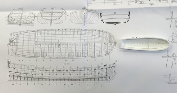
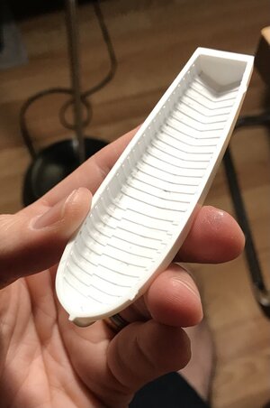
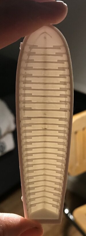
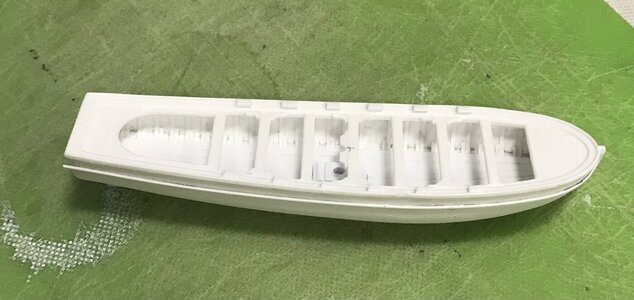
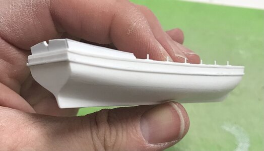
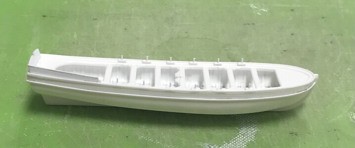
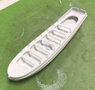
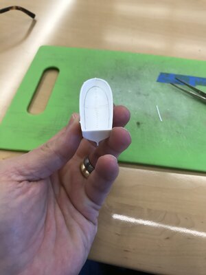
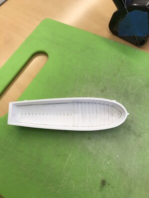
So, I decided to focus on detailing the ship’s boats. I started with the grand chaloupe - the larger of the two.

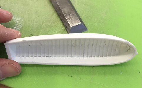
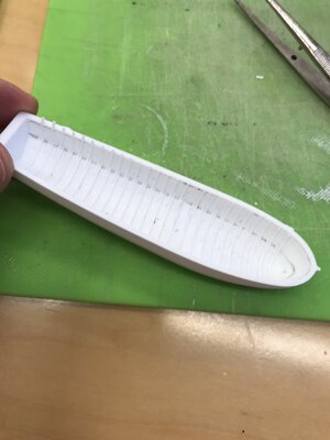
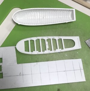
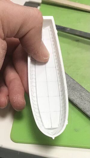
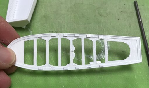
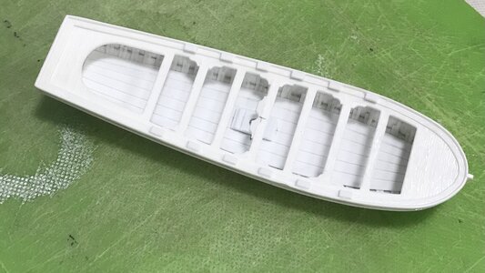
I am using the St. Philippe plans as a reference for their detailing. I won’t go all-in, but I will add frames to the interior, floor planking, a mast step, bowsprit brace hardware, bench seat braces, oar locks, and a small aft sheer step. A few pics of the framing process that includes floors and futtock top timbers:
AC1B519F-652A-4FC4-8CD4-951B5734E78E.jpeg
The plan shows some 27 frames. At 1/8” spacing, I managed 26. Interestingly, at a point just forward of midships, the top timber futtock placement runs forward toward the bow, and aft toward the transom. I’m not really sure why that is, but that’s what the plan shows, so that is what I did.
E575F882-8359-4DFE-ABD7-9037788B4B9A.jpeg
To establish the floor spans of each frame, I simply sketched in a line midway through the turn of the bilge. I did it by eye. It is reasonably symmetrical. The floor timbers will be mostly covered by the floor planking.
A9FA758F-75EE-4F13-B88B-71F7C5414598.jpeg
D0A52DDC-6A46-4F16-AA14-96B259249681.jpeg
Once the floors were in, I trimmed their ends for a fair run, fore and aft. Then, I started with the top timbers:
9209252D-F462-4C05-B2A9-12DB6F21C147.jpeg9E3DC373-09F6-46E8-9566-ABCF47DF2C0D.jpeg11FF7E45-D88E-4310-95FA-4188BB19B78F.jpeg
I had traced a line one heavy 1/32” below the sheer. I trimmed my top timbers to this line because the kit bench framing has a glue lip that requires clearance here.

These glueing operations are inherently messy. The frames are cut from .011 x .033 styrene strip stock, and one must apply a liberal amount of cement to afford enough open time that the small pieces can be tweaked into position. After the floors were all in place, and the glue had cured overnight, I came back and scraped away the excess glue with my 1/8” chisel, scraping on a skewed angle between frames. This is tedious, but it works well enough, and ensures that distracting glue ghosts won’t telegraph through the paint.

I have decided that I will not be placing these boats on the main deck, over the gratings. I spent too much time adding camber to those gratings to cover them up. Their presence on the main deck would also conceal what is visible of the stoves. Instead, they will be set into the sea and tethered to the ship through the stern chase ports, as is often shown in VDV battle portraits. In light of their less prominent placement, all of this detailing is probably excessive, but I am a man of excesses, afterall.

In the evenings, I have been building the underlying structure of the QGs. It made sense to me that the logical starting point would be the aft-facing window, working forward. I will try not to, but I could write a book about this aft corner.

Let me post this much, and then I will continue in a second post. Cliffhanger alert: my so carefully rendered plans were not as carefully considered as they should have been :eek:
 
Last edited:
One of my first revelations was that the aft-facing window must also follow the continuation of the stern round-up. If I were to position that window square with the ship’s side, then it would create an awkward angle along where the window bottom edge meets the transitional moulding that it sits upon.

The other thing that quickly crystallized in my mind is the difference between drawing something in the one-dimensional plane and the practical application of that drawing to a space that requires compound angles and elegant transitions between curved and flat surfaces.

To begin with, the outboard edge of this aft-facing QG window has a subtle curved profile:
3FD43A2A-FD49-4D94-B48D-33FD9613CEBB.jpeg
I very much wanted to include this detail because it is one of the many small details that would be glaring, in its absence. The difficulty is that the three windows of the side QG exist in a flat vertical plane, angled-in towards the ship side, while also conforming to a elegantly bowed horizontal plane (more on that later!:mad:).

First, I decided to provide myself with a pair of glue cleats that would help position these aft windows on their back-raking angle, while also conforming to the round-up:
291ED46D-D36F-420E-A074-5CA49AE9E800.jpeg
Forward of those cleats are a series of reference lines drawn at a right angle to the ship sides. These lines delineate the aft window backing-block and the window pilaster framing gussets.

Next, I needed to make the backing-block. I had some 3/8 stock left over from the making of the lower finishing. This was exactly the right width (according to my flat 1-D drawing that neither accounted for round-up or outboard bowing), to provide room for the aft-most pilaster, the crossed diamond ornament, as well as a 1/16” landing ledge for the aft edge of the window plate to recess into.

So, I first cut the back-raking angle onto a piece of this 3/8” stock, and then I scribed it to the tumblehome.
9D4C1683-BCCA-4886-8BED-FDB720C2033C.jpeg
With that much established, I could then lay-out the outboard angles and profiles. A photo montage that I hope will explain this better than I can:
081D04F7-5F7A-4936-8C7D-34F80A6DA112.jpeg
DF203483-F38F-4103-ADF7-C6E7E95C2110.jpeg
Here is the fore-face of the block. That shadow-line on the side is the transition from the flat vertical plane of the side windows to the curved pilaster of the stern profile.
3A6DA32A-B9C6-46B9-B341-4CD1539F9059.jpeg
The aft face of the block has a small styrene spacer strip that abuts the aft-window glue cleat:
AAF2384D-1A82-4B3A-8582-E3B7FA4A4C9E.jpeg
The aft-window held in place - I am riding pretty high and feeling really good about myself, at this point.
84DF59CE-3E91-4AE6-A77A-82C9EDCA725F.jpeg
I had established the interior depth of the pilaster gussets and made the first of those:
736EF6BA-5B57-4AA4-AEB0-0AB462376F16.jpeg
EE9CBBD8-1965-44BD-A8CE-45DDAEFAEBA8.jpeg
Initially, I had cut the height of this gusset too short because I was foolishly thinking that it sat perpendicular to the transitional moulding: it does not, obviously (after finally seeing the reality of it), because the windows have a back-raking angle.

No biggie! I simply glued strips of styrene to the top and bottom edges of the gusset, and then beveled them, accordingly.

I went to bed feeling accomplished - like “a million bucks!”

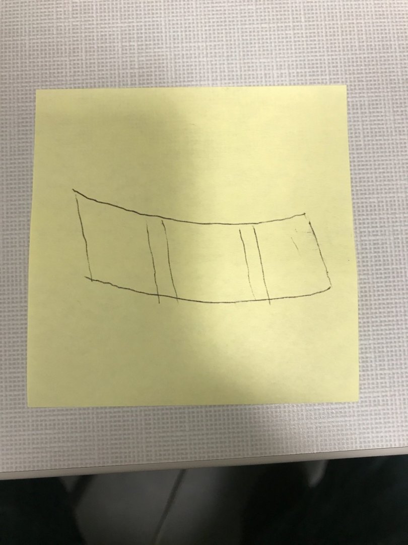
I woke up, though, to a horrible realization. My window plate - drawn in a flat, one-dimensional plane - has straight and parallel top and bottom edges:
C268A10B-532E-433A-8E6A-0A6710056B95.jpeg
In order to conform to this space, that billows outward in a gentle curve, while tipping in, toward the hull, this window plate must actually be shaped like this:
image.thumb.jpg.37cff9b1cc9258a2747a1ee29d88ed77.jpg
Well, that is a bit of a set-back! There remains the small possibility that I may be able to extract and still use the frames that I spent so many hours making.

I won’t really know, however, until I complete the underlying framing, as well as the forward block, and can make a cardboard template that fits this space.

Maybe the plate I made can be scribed without losing detail. I sincerely doubt it though. My preliminary quick test on a flat surface looks as though I’ll lose about a tapering 1/32” at the bottom ends - which might be doable - but, also, a probable 1/16” at the top middle, which is not doable. I have zero margin at the top, or bottom, for that matter.

If that weren’t enough to chew on, I probably made the windows too tall, in the first place, which means that my window panes are probably also un-salvageable.

I won’t know for sure, though, until I have a working template to compare against.

And things were moving along so nicelyCautious

More to follow...

Update within the update - last night I made the forward pilaster gusset and could accurately gauge the degree of bend that would be required of my existing window plate. It is not at all salvageable. It will look horribly compromised to fit, and would spoil the effect of everything around it. I will make new windows. At least the stern-facing windows are good! Anyway, this is disappointing to me, as the windows and frames were really quite good, but sometimes one must bite the bullet!
 
Last edited:
Many thanks, Maarten and Uwek!

Work on the grand chaloupe continues:
AFA60323-AB1F-4078-8C75-AF1238B8E17E.jpeg
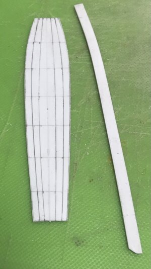
Above and below, I’m laying out the floor on a 1/2” grid.
09A20548-75BA-4395-B807-199882B2C48A.jpeg
I simply took measurements to one side of the centerline, so that ultimately, the doubling of frames would still be visible:
A53B6CEB-9F21-4632-927E-6E49A12D2E59.jpeg
I laid out tapering planks:
3E7BC3CA-4B72-4C01-9A79-F1B6925C850E.jpeg
Although the chaloupe is some 30’ in length, I am not going to show any butt joints in the planking.

Below shows the series of shaping steps for making the bench corner braces:
621E2268-343C-4619-AD96-C3D53068964C.jpeg
From lower right to left: the glued-in blocks; angled waste cut made with a triangular file; and final shaping with rounded files. These pieces are too small to work without them being attached, so it is just easier to shape them, in place.

Note, also, the oar-lock blocks that have been added.

I added a mast step:
BAE3BA37-4D31-4C70-8123-BA9110FFFA3E.jpeg
8352D35C-CDE9-402E-97D6-4CB20B8E1FBC.jpeg

Note, also, the rub-rail that I added below the sheer.

French chaloupes always seem to have an elegantly tapered sheer step at the stern, so I patterned that, and gave the transom a nice rounded top profile:
D453012D-173B-4D10-A4D5-046E30443477.jpeg
3540265C-F36B-4D68-8A87-08A1278FC985.jpeg

As it stands, this is quite a lot of nice additional detail. After finishing up the other sheer step, I will probably add a metal mast collar, at the bench level, as well as a bowsprit collar next to the stem. The stem top will also be replaced so that it might more realistically buttress the sprit mast running right beside it; the little nub that the kit provides is not sufficient.

Work on the starboard QG continues. I made and fit the forward block, and also attached the outer pilasters to these fore and aft blocks:
CC796AED-BE32-4517-9A26-C9F6260E6178.jpeg
EB7927CC-73D9-46E1-BBF5-5B0132DD20BA.jpeg

With all of this structure in place, I could begin leveling all of the tops.

One really fortunate bit of news: I realized that I could remove a 1/16” from each side of the window panel. Even that small difference significantly reduced the amount of material I would need to remove from the bottom corners and top middle, in order to get the window plate to fit within this parallel space.
5959694A-D8E6-4952-912F-1DB176E48423.jpeg

The pilasters will overlay and cover this join between the window plate and the end blocks.

I still have to fair the top edge, but even if I dip into the ornament topping the central window frame, I will probably be able to alter the carving a little to make it work.

The gap remaining at the bottom can be filled and faired with a strip of styrene, and the pilaster bottoms can also be filled-in and faired. The bottom gap is only a heavy 1/64”.
3A77140D-245A-468A-B692-2C91D71E7387.jpeg
Here’s the plate, resting in place, to give an impression of what it will look like:
FEF981B2-5513-46EE-82BB-F8066E842AF7.jpeg

Earlier, I made the transitional top mouldings that serve as the base of the walkable, wrapping stern balcony. It has yet to be reduced, in depth (from hull), or scribed to the hull side. The extension, off the stern, is also over-length.

2B6E37A4-AEDF-4C59-9FFB-A1EA824A6B3E.jpeg

I am relieved that it now seems likely that I can use my window plates, after all.

Little by little, we are getting there!
48A13CED-F796-4ED0-B0AC-9179018D4794.jpeg
 
Back
Top