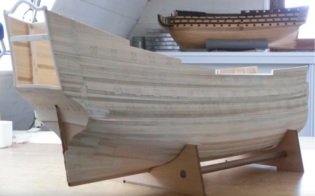
Soleil Royal by Heller - an Extensive Modification and Partial Scratch-Build by Hubac’s Historian

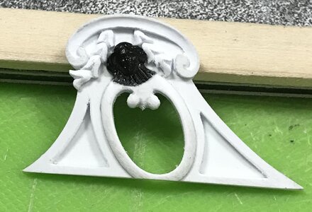
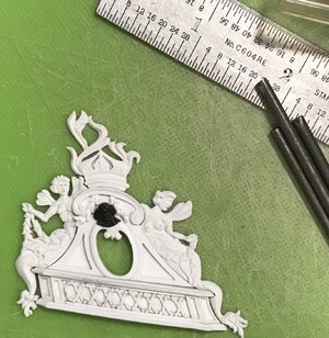
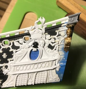
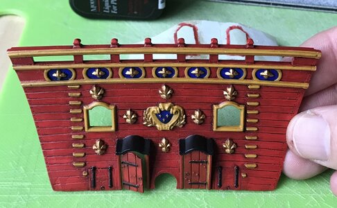
So, the upper finishing of the amortisement has been straight-forward but surprisingly labor intensive.

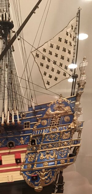
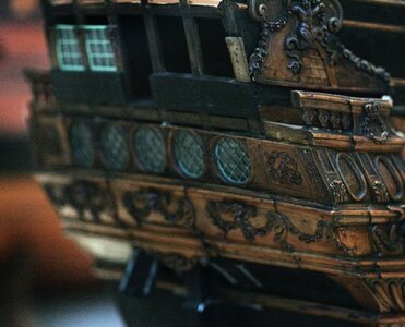
This particular photo of Tanneron’s damaged model of L’Agreable is so instructive because it provides so much information about the fabric of his construction, as well as the shaping cues for the upper finishing of the amortisement:
D987F473-5AF9-4428-823B-2E1C1CAF18A1.jpeg
My ambition, always, is to attempt to capture some sense of the magic that makes Tanneron’s models so impressive. Toward that end, it’s a process of layering details with all of the care of execution that one can muster.

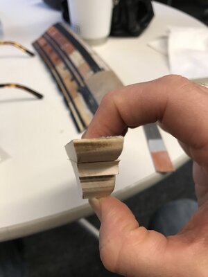
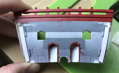
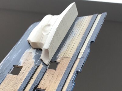
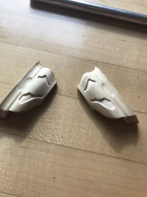
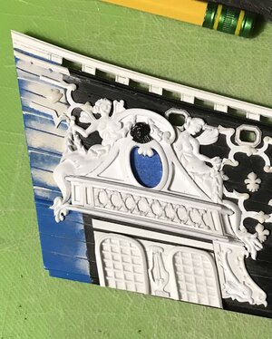
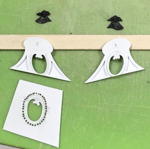
As has been my method, the upper finishing is made up of a series of laminations: a base layer of 1/32”, a middle 1/16” layer, and a top layer of 1/32”.

I toyed with the idea of using Bondo fills to fair panel recesses at a continuous depth. I did not think the Bondo would adhere well enough to the plastic to withstand the slight flex of fixing the part in place. Conventional model putty would be too brittle. In the end, I decided that the 1/16” layer was deep enough to create a sense of shape without having to go through undue effort for minimal gain. I think it worked out pretty well.

A montage:
E4952C9B-0F0A-46EF-9843-1D76989F3219.jpeg
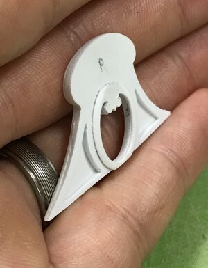
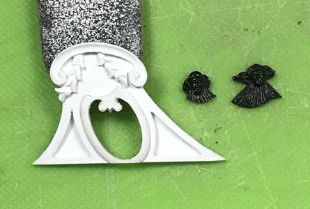
Given my struggles to carve good faces, I decided to extract Louis’s radiant head from the same place on the kit’s stock quarter galleries.

I wasn’t sure, early on, just how much space I would have left-over, after the bellflower garlands were in place, so I left the heads oversized for the time-being.
F047D44C-15A6-4653-8155-41FDC8CE4374.jpegE24F5642-B852-439F-A486-4348AE408131.jpeg

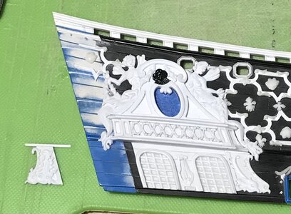
You can see the subtle shaping of the 1/16” layer, above, as well as the slight rounding of the final window framing.
0664131C-B985-4042-AC11-0F14CE7599D7.jpeg
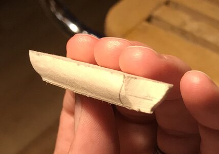
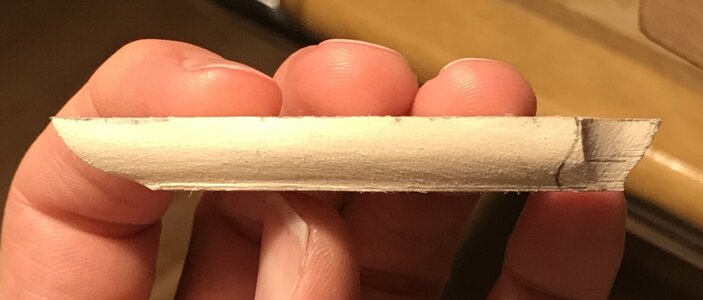
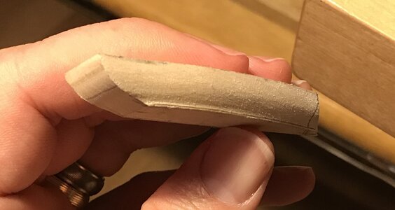
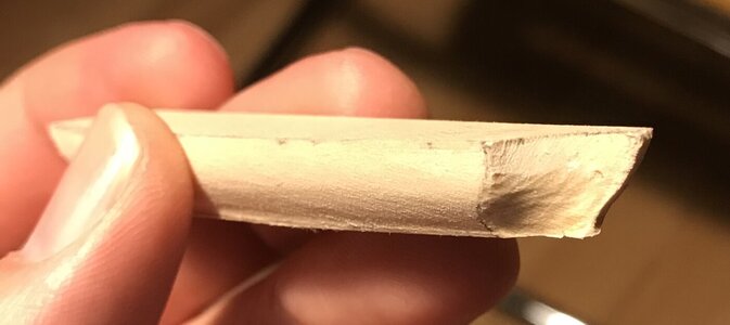
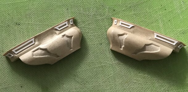
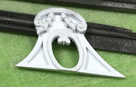
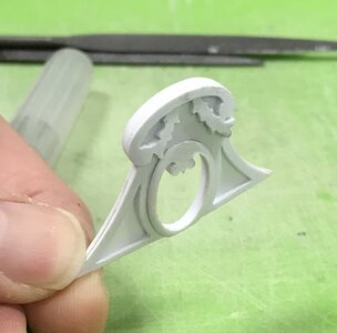
The garland and cornice were a separate 1/16” layer. Just as they are, above, they would be fine, if I decided to stop there. Attention to detail is everything, though, so I took the shaping a little further:
B82E845D-91A4-48C1-860F-860AA15ADEA9.jpeg
The garland diminishes, in depth, as it rises to the cornice, and the cornice, itself, is now tapered in a gentle arc from its center to its ends; this small detail helps to accentuate the convex shape of the windowed center, below.

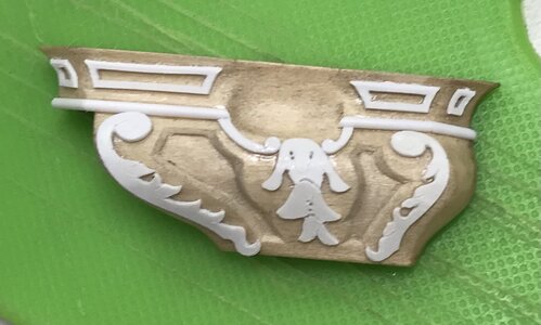
I coved the inner surface of the cornice, modeled the bellflower garlands, and then I gave Louis a haircut. I was able to incorporate just enough of the fanning rays of light, beneath his head, to satisfy the original design:
494E4317-56F7-49C7-8642-3C64F6C5A271.jpeg
3CACC8E6-CB15-459D-90B7-767A8C187B8E.jpeg
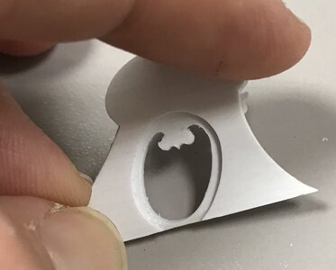
The first layer creates the recess I need to capture the acetate window:
E09BEE42-4F24-4DDB-911D-A7A009007B41.jpeg
I made up the acetate panes, yesterday, but botched the engraving on one, and will have to remake that.

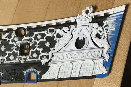
So, now that I have all of the elements of the amortisement, it was time to see how this was all going to map out on the upper bulwarks.

The whole layout hinges on exact placement of the canopy section. Although the uneven underlying ornament makes it difficult to place these pieces, and the parts have yet to be faired to each other - this placement should enable me to salvage my aft octagonal port:
A517C9E3-963C-4810-A742-9B248A8FED5C.jpeg
I will have to drop a wing from the forward pixie, but I am now confident that I will be able to make this work.

With my kids back in school, and the uptick in their activities, I have found that I am not sufficiently alert, in the evenings, to do good paint work. All of the putty fills at the bow are nicely faired and I brush-primed all of the raw plastic, but I just haven’t felt like I could give it the focus it requires. Opportunity will present itself in the coming days, though.

As ever, thank you for the likes and for looking in!
 
It has been a slow week of mixed results and some small progress.

Painting-in of the head timbers was going well enough. Unfortunately, I over-estimated the blending capability of Van Dyke Brown oil paint to conceal the color-fills I made to the ventre-de-biche of the deadworks.

I thought I was being careful to feather-in the new color, yet because of the contrast of the original weathering, I still ended up with a clear line of demarcation:
DD657880-BA96-4E4C-A9C3-762617AD25C3.jpeg
4FA82498-7205-4B0D-AC9B-B8FB25309395.jpeg
This was after two applications of oil and wiping off the excess.

Part of the problem is that the original weathering is sealed under a clear top-coat, so I can no longer lighten or manipulate it. I can only go selectively darker. Toward that end, last night I began applying heavily thinned wash-coats of the oil paint, and have succeeded in eliminating the strong contrast. I didn’t take additional pictures, but the appearance is much improved.

At the moment, though, the color appears a bit mottled, as I was applying the color with light dappling touches, over and over again; a brushing motion only “washes” away the color you put down on the previous layer.

I then charged the chip-brush I’ve been using with un-diluted oil paint, and left that to semi-cure overnight. My hope is that, this evening, the wash-coats I applied will be sufficiently durable that I can take light sweeping passes with the charged chip-brush to smooth the tone and blend back smoothly into the ship sides. We shall see.

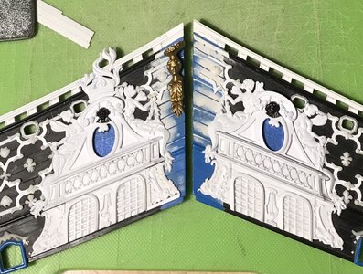
In preparation for building up the amortisement on the upper bulwarks, I coped together all of the individual parts, and this helped me feel better about the paint problem.
D7C09F5B-D005-4CC6-A2BA-B7372BDAD819.jpeg
Thank you for looking in, and enjoy your weekend!
 
After days I still haven't finished reading this great construction report. In fact, I have to reread many of the sections to understand the wealth of techniques and clues. This is without any doubt the most complex and successful conversion of a plastic model from a kit into a highly authentic ship model I ever came across. Already now my congratulations on this fantastic project.
I feel very connected to your work, because I am also a disciple of Herbert Thomesen from Amsterdam since several years. I started to build and paint his resin models under his guidance. Meanwhile I dedicate myself to plastic model kits of ships on a smaller scale (1: 150), but still use the same techniques. Your advice on the color design of the surfaces exactly applies to my practice.
All the best for the project: Schmidt
 
Hello, Schmidt! Thank you very much for your kind appraisal. It is very gratifying to me that you have taken such a strong interest in the project.

Although very brief, my time with Herbert was remarkable for his complete willingness to share his techniques and research. In the intervening years, I have found this character trait to be fairly rare, among the super-talented.

I remember standing in his workshop, holding his model of the captured English Swiftsure, and marveling at the absolute realism of his creation. It was a Van de Velde portrait come to life:
932F5CF6-D117-4899-8A17-35DAAB1A4C7D.jpeg
Herbert made more ship models for that Texel Roads diorama than I could ever hope to, over the course of several lifetimes. His productivity and exceedingly high standard are truly astounding.

I would love to see some of the work you are doing, Schmidt. Do you maintain any build-logs?

Personally, I have always thought the Airfix series, in 1:144, were some of the best plastic sailing ship kits available. If one takes the time, as perfectly illustrated on this site by Rex Stewart, these kits can be transformed into museum-quality works of art.


If it interests you, Schmidt, there are many, many more pages of research and analysis of SR1’s better understood contemporaries on my original build log:


There is an evolution in my conception of the ship, as people from all over the world have helped me to better understand her and the construction methods of the time, between 1668 and 1693.

As ever, thank you for your thoughts and for looking-in!
 
Last edited:
It is a shame that Herbert Thomesen only constructed a few kits of his wonderful models. I heard that others were being planned, but apparently the project failed because of the high price that such a kit would have to fetch on the market. A few years ago I was able to persuade Herbert to let me have on of his hulls (7 Provinces, flagship of Admiral de Ruyter). However, I am afraid I will never finish building the model.
You yourself stated the reason for this. I am also absolutely of the opinion that some of the early sailing ship models (Airfix, Revell, Heller) form a great basis for creating wonderful and authentic ship models on an approximate scale of 1:150. I myself have been trying to do just that for years. The smaller scale suits me because I want to arrange the finished models into dioramas that, when photographed with a certain technique (and with a little help from Photoshop), are supposed to create the illusion that Van de Velde was already out and about with a camera. I am still at the very beginning with this technique, but if you are interested, I will be happy to present a selection of my previous attempts with various kits and self-constructed models in this forum.
Schmidt
 
By all means, Schmidt, please post pics!

So, you have a resin casting if Provincien. Herbert also gave me a defective casting of a lesser-rated Dutch ship. I have considered cutting it down at the waterline and showing this Dutch vessel sinking as it burns in Soleil Royal’s wake at the Battle of Beveziers.

It’s a nice ambition, but I really don’t have presentation space for a case so large. I keep the casting, though, as a reference to Herbert’s detailing techniques.
 
Many thanks for the invitation! In fact, I post a number of construction reports on various forums. They are, however, very explicit and detailed, and I'm afraid a link to them would only bore you all. In addition, they are all written in my mother tongue, German. Perhaps I can therefore choose a different way and offer a tour through the world of my ship model building in this forum. I would present my most important projects with pictures and little text.

Schmidt
 
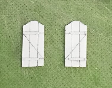
Thank you AMac! This has been an enjoyable discovery of where and how I can upgrade the kit. For example, last week it dawned on me that the beakhead bulkhead should be fitted with doors, to protect against swamping the decks in a heavy seaway. So, I have busied myself with making those. I try and take the detailing to the next level, though; the hinge straps are embossed with nail heads and I will represent square-head nails along the Z-bracing that holds the plank door together, from behind. Like so many details, though, because these doors are absent from the Tanneron model, they are missing from the Heller kit as well.

Schmidt - what I sometimes say about my own verbose log is that this information is available for anyone to absorb, refute or ignore, as they choose. If people just enjoy looking at the pictures, I am absolutely cool with that.

Personally, I enjoy the super-detailed build-logs - even if written in German. Another German friend, on this site, affectionately calls this tendency of mine “data mining”. By all means, please post links!

I never know where I’m going to find unexpected treasures, and for whatever reason, Baroque ship-modeling is alive and well among German builders.

I haven’t done a “milk carton” post in a while, so I will take this opportunity to do so.

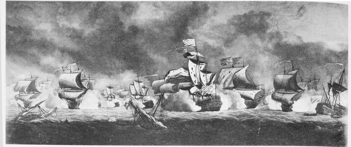
Has anyone seen the originals of these portraits lately? Can anyone tell me their present whereabouts?
80185EC6-9EA9-431F-8459-A3ADF6AF533B.jpeg
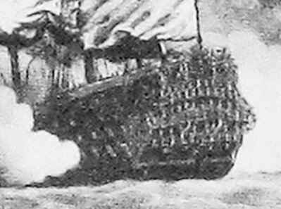
An inset detail of SR:
84EBA004-7D84-41E1-A398-FCD367A68C10.jpeg
The above is a portrait of the Battle if Barfleur, perhaps by the Van de Veldes, but most probably by someone in the VDV studio.

If I could get a better resolution image of this portrait, it may go a long way towards validating what I’m doing on this model.

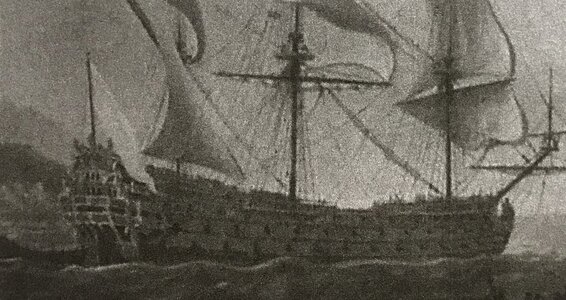
The second portrait appears to be the work of Puget, but all that I have of it is this low-res image:
FAAF51B3-AFEB-4271-90DC-209ECC17F539.jpeg

Here’s a somewhat cleaner view:
1987AF19-994A-4317-B9FB-1586F5797003.jpeg
I do not think this is the Royal Louis. It may, in fact, be the only coherent portrait of Soleil Royal hefore her refit. There is no way to tell, though, without a better resolution image.

If anyone out there has any information about these portraits, I would be greatly indebted to you.
 
Last edited:
The past few weeks have been mostly about tying up loose ends. The bow area is nearly done with the paint re-touches. I also realized, recently, that the beakhead bulkhead should be equipped with doors, in order to prevent heavy seaways from swamping the middle gun deck. I got myself busy making a pair of those:
81E592B1-04E6-4275-8E6B-83151F4DAAE3.jpeg
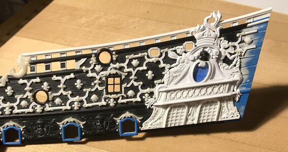
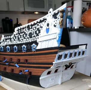
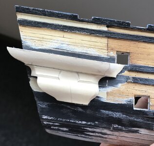
I also spent quite a lot of time building up the port side amortisement:
CD01E906-1659-4F94-842C-6E92BA11DFB4.jpeg
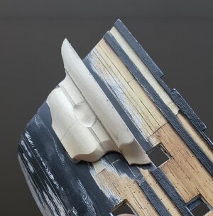
I took extra care to beef-up the portion of the crown that rises above the sheer rail:
3CBF310E-06DF-4423-A56E-2E5DEE678B55.jpeg
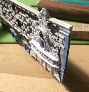
One can get a very good sense, here, of just how shallow the amortisement really is.

The next detail I wanted to affix before priming the upper bulwarks are the quarter pieces that support the side lanterns.

One peculiarity of the Heller kit, vis-a-vis the Tanneron model, is that the side-lantern support boxing rises above the sheer rail. This contributes, greatly, to the exaggerated height of the tafferal.

For reference, here is that detail on my first SR:
B50C45B6-F613-4097-A094-D3656663AAAB.jpeg
Note, the extreme difference in style between the kit QG and the 1689 version. This transformation has been the primary motivator of the entire project.

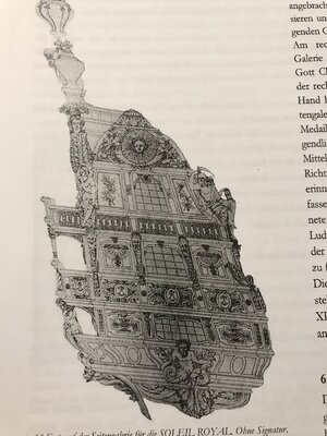
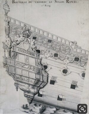
I suspect that Tanneron took his cue for the lantern boxing from this later QG drawing for SR2, in 1693:
90927FD3-07BF-43F4-9F30-006E85E5C416.jpeg
The earlier drawing, though, shows the boxing below the rail:
8CA5FA6F-D5C7-4EE5-B5F9-343071587A00.jpeg
As a constructor of things, and considering just how massive the side lanterns actually were, it makes much more practical sense for the lantern boxings to mount solidly to the ship’s sides. There also exists a solid foundation of Van de Velde drawings to support this detail.

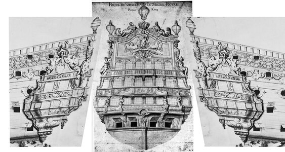
Using Dan Pariser’s Photoshop collage as a reference, it seems more likely that this, in fact, is the arrangement that was intended to correspond with the stern drawing:
E311218A-BA3D-487E-B0F2-AFEE16BB05A4.jpeg
Thinking back to the start of this project, this lowering of the side lanterns was how I decided to shorten the tafferal tableau for Apollo’s horse-driven chariot.

As I do when the opportunity presents itself, I more deeply defined the acanthus detail of the quarter pieces, while cutting away the unnecessary lower portion:
6BF7087E-A937-47CF-9C42-7DC1471BFA92.jpeg
My hope had been that I would be able to re-cycle the kit figure of the Americas, for the port side, but she is scaled for the much taller tafferal, and she now looks too far out of scale. As I was going to have to carve Africa, anyway, it is best that the Americas be proportional.

I have also begun making the lower section of the QG. Henry’s hull continues to be invaluable. Without being too delicate about it, I could grind away the wales in the QG area, so that I could closely fay each section to its location:
9ECE6FDD-5E8E-4A5A-B0CB-6CF8EE166F0A.jpeg
7D630B79-1DD9-4AC2-8BA6-C288DCD4033A.jpeg
8CEC6C46-7607-4EB1-8B92-ED3814759B01.jpeg
There will be 1/16” styrene spacers between these sections that define their shape, while providing the moulded transitions.

More to come! As always, thank you for the likes and for looking in.
 
Last edited:
Hi Marc,
I would have to say I find your work mind boggling, in my opinion you are a master craftsman.
It also strikes me that for the real ship, with all the money spent on decoration the French would not wont to risk damaging her in action, as she must have cost a Kings ransom to make.
Cheers,
Stephen.
 
As ever, Steve, I really appreciate your kind compliments! It’s almost embarrassing how much time I spend on this project, but such is my obsession, and it makes me happy. In these pandemic times, one must take their kicks where they can find them.

A large part of my fascination with Soleil Royal has exactly to do with the fact of her existence that you just alluded to, Steve; like the Royal Louis at Toulon, Soleil Royal was designed to be a symbolic beacon of the prestige and military might of the arsenal, at Brest. Beyond her initial sea trials, Colbert had little intention of actually deploying her in battle. So, there she remained - anchored at the mouth of the harbor, being magnificent and slowly decaying. In all likelihood, owing to the shortage of bronze guns, she probably spent much of those first 20 years lightly armed, if at all.

At some point, though, Louis and Colbert realized that military symbolism could only carry a navy so far. Sooner or later all of those guns would have to be brought to bear on France’s adversaries. As splendid and terrifying as the ship must have been to behold, in the line of battle, it was the cunning skill and fearless leadership of Tourville that carried her through a horribly overmatched conflict at Barfleur.

Under the command of a lesser admiral, Soleil Royal may never have achieved the almost mystical aura that surrounds her for having survived the battle, only to be cruelly destroyed out of spiteful revenge.

Although the English built many fine and splendidly ornamented ships, the French took it to an architectural extreme of artistic refinement; the artists and artisans that ornamented the King’s ships were those same that were ornamenting the palaces, estates and churches of French nobility.

For all of these reasons, I am on a quest to assemble an artistically and architecturally plausible portrait of what Soleil Royal MAY HAVE looked like before her refit.

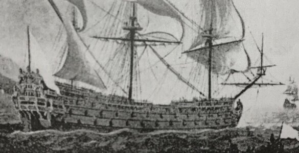
The sculptural allegory and overall ornamental program would be different, and the dimensional particulars would reflect her unique size, but I truly believe that SR1 would have closely resembled the Monarque:
CCE9240F-C8A4-48A7-A785-3D1249EA8036.jpeg
On the one hand, I understand why true scholars resist the temptation to delve into conjectural fantasies that have little concrete basis to authenticate them.

On the other hand, though, the discipline of archeology has always sought to assemble a coherent hypothesis from fragmentary remains. Subsequent discoveries sometimes reveal the degree to which the archeologist was right or wrong, but at least they dared ask the question, in the first place.

And, so that is what I will attempt to do - a kind of forensic reconstruction.
 
Last edited:
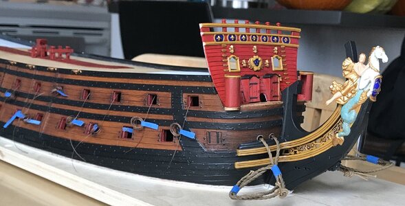
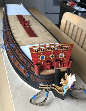
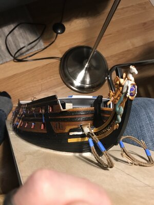
So, here are a few pics of the bow area with everything re-touched and distressed, the beakhead doors in-place, etc:
5A801728-2690-44BF-986A-B811867F7D98.jpeg219AC0D9-3F25-4BF9-B8A1-CEB2B4E6948C.jpegAC120211-2846-42E7-8906-6008F8B0F453.jpeg22074B43-2159-429D-ABA2-D68630536049.jpeg
I realized that I shouldn’t glue-in the beakhead bulkhead until I have painted the lower transom because I will need to remove the model from its working base and flip it over, in order to access the underside of the stern counter.

Just for fun, here’s what the built-up amortisement looks like in place:
31E389F2-4C7F-41D3-9373-E659B25E29A4.jpeg

I also realized that I can’t paint the lower transom until I’ve made the lower section of the quarter galleries.

I’ve held off on doing this for a long time, while I tried to figure out what exactly my approach would be.

The greatest difficulty is in trying to ascertain what the volume and shape of the sub-structures should be.

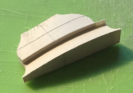
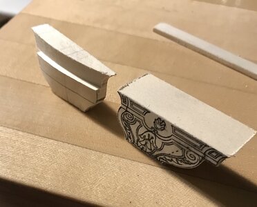
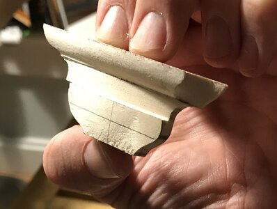
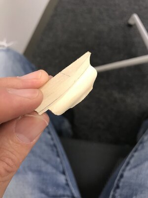
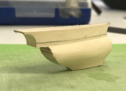
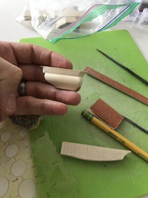
Ultimately, I decided that I would carve these sub-structures from apple solids, and use the pieces above to inform the shape of those below.

For additional reference, I looked back on Drazen Caric’s excellent tutorial for the making of his QGs on the Provincien:
(NOTE: I was not able to post the link from MSW)

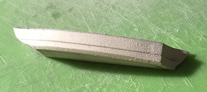
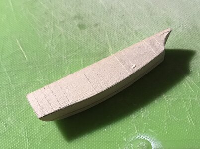
The logical starting point of this process seemed to me to be the widest section of the QG - the middle-deck section, which is the functional level of the officer’s toilet.

I know that the projection from the ship sides should be about four scale feet, or a 1/2”. As the above amortisement hints at, I wanted there to be a slight rounding of this level, at the middle, before tapering in towards the hull, at the foremost end.

The pictures below are a pretty clear evolution of this shaping process:
16C6930A-1D6E-46BE-B350-3E157D02A8B0.jpegFD421778-D747-4EBF-A9C5-D1D31DAE3DEA.jpeg12EB017A-D2CF-4843-B9FD-186AAF5CAEA7.jpeg3CEBBACF-7EB5-4EEF-8238-C44442640DB3.jpeg45D40A5D-2776-44E2-A8C6-B334E7908FD5.jpeg44B9364B-B1F5-4519-8E10-EAD98A448236.jpeg9BE05750-2B9D-4FB8-9C4D-ED8C01F92B86.jpeg
One thing worth mentioning, here, is that the projection of the false stern balcony is a bit exaggerated. This owes to the fact that I did not, initially, realize that there needs to be a shelf of sufficient depth to support the four seasons figures. Consequently, I had to graft-on an extension piece:
5EF310E5-6AB6-4880-82CC-2473EA17229F.jpeg
Ideally, the end-shape of the counter should match the moulded shape of the sides. That won’t be the case with this build, but it does not appear too distracting on the model. Lesson learned!
0FD7C248-A18F-4FAE-9DAA-839A7F614E3F.jpeg
Now that I had established this shape, I could trace its bottom onto the top of the piece below it:
CC1E685C-8C0C-464F-84FD-62F3A53A00B6.jpeg13269319-045C-4B72-AAF8-BF454FE0600D.jpeg75EEC1B8-5911-49D4-9109-27445C314723.jpeg81E1F7B1-6B15-4846-986F-D35B1481A492.jpeg6A37B0E5-8154-460B-AD4E-947FF88F8063.jpeg77FEA0A3-0F7D-4055-AB3D-D9CB09654F9B.jpeg84BC4FA0-AFAD-4B41-8671-DFC5017528C5.jpeg00CE4748-CAA2-4888-867B-745FE715C4E7.jpeg1423DF4D-5053-4865-B7A3-E086637BC7E2.jpeg
016EC31A-BC94-4A4C-948A-51052560A28C.jpeg
Please bear in mind that positioning on this scrap hull is only approximate, as the hull was cut down, in order to make my hull longer.

At this stage, I can begin applying all of the styrene pilasters, mouldings and ornaments that decorate these sub-structures.

Once, they are fully sheathed in their paneling, I can use them to determine the outside dimension and overhang of the transitional mouldings between sections.

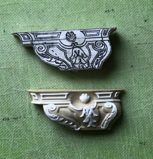
I am wondering whether I should sand and seal the wood with something before using CA glue to attach the surface ornament. Or, would I be better off sanding, applying surface ornament and then sealing with polly, or something else? I’m just concerned about CA adhesion, here. Also, considering that these wooden surfaces will be painted, how fine a grit do I need to sand to. Is 220 sufficient? The wood grain is very fine. As always, any advice is welcome.

Thanks for taking the time to visit! More to come...
 
Last edited:
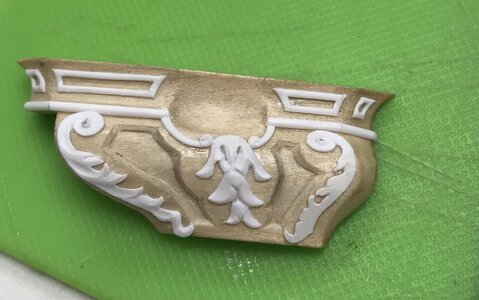
After sealing with plain old brush-able Crazy Glue, I sanded smooth with 320, and then transferred the patterns for the inset panels.

When Dan gave me this wood, he told me he thought it might be apple, but that it had been sitting around so long, he had lost track of what it was, or why he had bought it. I was impressed with the stuff because the grain was absolutely clear and even, and the stock had remained perfectly flat and straight for over a decade without any special handling.

Although I had never worked apple before this, I have to say that I think this wood might be some other species. I was expecting “apple” to work with roughly the same density and hardness of cherry, for example.

This material is nothing like that. It shapes beautifully, and easily, but it is fairly soft and a little thready; strands of grain can pull away from the surface, fairly easily, if you are not careful, and if your tools aren’t razor sharp. While I thought my knives were sharp, they were crushing/compressing the grain, as I tried to carve the beveled border. So, I sharpened my knives.

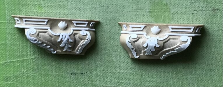
Here is a montage of the lower finishing as it has come into focus:
6CFC3A97-B5FF-49E9-85E1-2FBDC376E954.jpeg
61A4B94C-F87C-41BE-B46D-13FD32B972A1.jpeg
A1C1FC49-C8AC-4F4B-903B-D32BFDE6FFDF.jpeg
Now, I made a mistake, here, in the placement of the bellflower ornament. I placed it according to how I thought it was framed best by the central stile.

However, that’s not what was drawn. Notice how the scrolls meet in the middle, above the bellflower:
418D26CA-ABC6-4866-BF2F-2C382946148B.jpeg
I should have placed the bellflower a little lower, in order to accommodate this detail. A little finagling later, though, and I found that I like this alternative layout just as well. Grinding away and remaking the bellflower, on such a fragile substrate, did not seem worth the risk of ruining all of the work done so far.

Here are a few more detail images that show just what a difference a little modeling makes, once the outline of the carvings is clearly defined:
E0A08626-4CA7-4C08-901A-FA5B61558175.jpeg
389863B0-E8E6-48A5-B373-EAA70CA8FB4C.jpeg
Obviously, there is still some work to do on these. I’ve been much busier than usual, so progress has been slower.

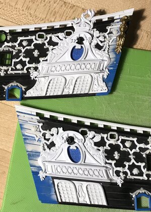
I have continued to assemble the starboard side amortisement. Everything from the canopy and above went down smoothly enough. I’ll have to do a few minor putty fills.

What I found really fascinating was the space available below the canopy, where the two false windows go; the space between the upper main wale and the canopy is a full 1/8” bigger on the starboard side than on the port side!
68CAF601-4378-414B-B5AA-5F3C5B591D90.jpeg
Now, for the port side, I did fill above the windows with a 1/32” square shim, and I didn’t even bother to fill above the dolphin ornaments because I got lazy and figured that the viewing perspective wouldn’t ever reveal that gap, anyway. On the starboard side, though, this is an additional 1/8” gap.

Up until now, I have encountered a number of these dimensional anomalies of the kit. In certain instances, while unaware, my modifications have probably exacerbated these differences. In this instance, though, it is a difference that exists and must be dealt with.

I think it is likely the case that when this kit was prototyped in the 1970’s, by hand, there likely was not the high degree of symmetry that computer modeling offers us, today. As a result, the model was made to fit together and had visual symmetry, if not actual symmetry. This is just something to keep in mind, for anyone contemplating a similar modification project.
B8238E1A-DFDC-4CB3-88D9-B3AB5D956DB1.jpeg
There is no way that I was about to re-draw and re-make the windows and dolphins. I am a field carpenter, after all, and being such requires one to just make things work, visually.

A few things are certain: the windows must meet the upper main wale, so that necessitated filling that space, above, with a tapered wedge of styrene. I also wanted the added framing pieces, beneath the dolphins to match what I had done on the port side.

Toward that end, I started with the forward dolphins. I coped them into the mermaid’s tail. I had to trim a solid 1/32” off the aft straight edge of both dolphin carvings, so that they’d fit between the mermaid’s tails. I then filled above the forward dolphin so that the space beneath these dolphins would match that of the port side. Here it all is in pictures:
9C309959-FECB-4F6F-A79F-FDC4307396C9.jpeg
C8269C63-9F01-400F-907F-71FD950E7CEE.jpeg
6D24E951-62B5-413B-9FA4-68C7EDF77F62.jpeg
I still need to fill in those lower framing pieces, but I think that, overall, I managed to mask those differences well enough. One can only look at one side of the ship at a time, in any case ;)

Well, steady as she goes. I’ve cleared the space on the hull where the active seats of ease are located. Soon, I’ll scribe in the wales, so that I can fit those pieces and then I can clad them with all of the styrene rails, stiles and ornaments.

After struggling mightily to paint the bowsprit, on the model, I will certainly paint these QG sections off the model and install, afterwards.

As ever, thanks for the likes and for looking in!
 
Last edited:
Back
Top