It’s been a good weekend for painting.
The primer coat is always a pretty solid indicator of how uniform your surface prep was:
View attachment 197491
I love the primer coat because it homogenizes all of the different materials.
A few pics of the process:
View attachment 197490
My initial thought was to take the cerulean blue (Utrecht artist acrylic, heavy body), and add yellow ocher to arrive at a more greenish blue; a light blue with a greenish cast would be a more period-correct, common blue that would have been derived from copper salts. What
I arrived at was teal, and while I like the Charlotte Hornets uniforms, this is not quite the look for Soleil Royal!
So, I went back to my cerulean base. After all, the following Corvette model was largely my inspiration for my color scheme. I really liked the way this light blue relates to the yellow ocher, even if it is a more stylized choice for my period:
View attachment 197494
My cerulean base-coat looks like this:
View attachment 197489
Here’s the rest of the process:
View attachment 197488
View attachment 197487
View attachment 197486
Et, finalement:
View attachment 197485
I spent quite a lot of time dialing-back the walnut ink distressing so that it wouldn’t be too much. I think the walnut ink does tone-down the blue enough to be plausible for 1689.
I also switched from my self-mixed Tamiya yellow ocher to Vallejo’s Mars Yellow, which is pretty exactly the shade I want right out of the bottle. While I still have to go over the work 2-3 times for the color saturation I want, the next coat doesn’t lift the previous coat, as with Tamiya. This characteristic of the Tamiya paint makes it extremely frustrating to work with. Considering the sheer volume of ocher paint that is going onto this model, a change to something more user-friendly was imperative.
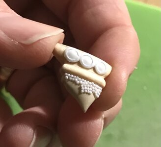
This is probably the best window into what the general paint scheme of the stern will be. Ultra marine will make very selective appearances. I thought about painting an oval of ultra-marine around the shells, but I didn’t like the only partial framing of moulding.
It’s obvious, I suppose, but worth re-iterating how much easier it is to paint these ultra-detailed surfaces, off the model; you can find whatever angle you need. As I consider it now, I’m really starting to dread the paintwork I have waiting for me on the lower stern. At the time, though, I couldn’t see any other way forward than to construct the stern in-place.
Today, I will start the waste-pipe rosettes.
On a side note: I continue to watch the Tally-Ho reconstruction, on YouTube with rapt fascination. With the exception of the transom and the possibility of eventually salvaging a few if the teak deck housings - she’s an entirely new vessel.
One can’t help but be struck by the incredible effort required to resurrect this relatively small wooden vessel. I suppose Leo could have saved considerable time, if he had just started, all new, from the ground-up, rather than extracting the old keel from beneath the framework, and replacing each frame, individually. The point of doing all of that, however, was to remain as faithful to the original shape and construction, as possible.
I mention all of this in contrast to the Jean Bart project at Dunkirk:

espacetourville.com
Next to the stalled Provincien project, this is the largest wooden warship project, currently under construction (as far as I know). As I was with the Provincien, I am amazed that they continue to frame the Jean Bart in the open elements. It is one thing to allow a ship to stand in-frame for the better part of a year, in order to season the timber. A 10-20 year span, in the open elements, is an entirely different matter. Leo and his crew of volunteers that he individually trains, will spend another couple of years completing Tally-Ho under a shed-roof. Hermione was constructed under shelter. Jean Bart may be rotting before she even hits the water. This seems inevitable, but avoidable.
Anyway, all of this got me to thinking about the value of these wooden ship re-constructions as trade-training vehicles and eventual tourist attractions; they’re great while the money pipeline keeps the project afloat, but if the funds dry up and you have a major catastrophe (like the BataviaWerf fire), then the project never comes to completion and thousands of trees died in-vain.
I was, dreaming about the possibility of eventually drafting a full set of digitized plans for my conjectural reconstruction of SR, 1670. This morning, it dawned on me that those plans could be fed into CNC machinery, in order to produce fully shaped/beveled parts at 1:1 scale. Well, that would speed up construction!
Every piece would still need to be fit and faired into place, but the time savings would be enormous. I suppose, in a symbolic gesture that respects the soul of the ship - her keel, stem and sternpost should at least be fully cut and fit by hand by a seasoned shipwright. But, as for all the many floors and futtocks and knees and etc - why not use technology?
Now, I don’t know whether CNC programs can be run to optimize within only the heartwood, or to pattern along an optimal run of grain for all curved parts, but it is an interesting question, nonetheless.
Despite the absence of a convincing model to represent the project, the Jean Bart’s framing, so far, looks very good. It will be a real shame if the project never reaches the finish line. Anyway, just something I am thinking about.
As ever, thank you for the likes, comments, and for stopping by!


")