Soleil Royal by Heller - an Extensive Modification and Partial Scratch-Build by Hubac’s Historian

Hi Aurelien - sorry I missed your post, here. I have this book. It has been a while since I last looked at it. My recollection is that this is a solid accounting of the development of the French navy - particularly as it relates to the First Rates. A lot of this historic contextual detail has also been well-covered by J.C. Lemineur. If you are really hoping for a super deep dive on the SP as she first was, then you will be disappointed. There is some good information, of course, but it is limited. To be fair - this is just off the top of my head, and I haven’t looked at the book in a couple of years.

Similarly, JCL’s Les Vaisseaux Du Roi Soleil would seem to promise a treasure trove of info about SR1, but the same problem of reliable information exists, there.
 
I noticed when I got Lemineur book, still verry informative. For you, would the soleil royal windows of the initial be more as shown in Berain drawing or as described on royal louis (1 door with 3 windows on each sides, page 26 of the gallica document). How's the spelling in Patrick villiers book? Asking because I've seen complain on it.
 
I strongly believe that SR 1670 probably had more than the six windows in Jean Berain’s drawing of 1689.

I base that belief on SR’s near sister ship, La Reyne, launched the year before and also built by Laurent Hubac. She shows two rows of 8 lights on the middle and main deck level.

7D2D8807-048B-43D6-B2FF-C14658CA9285.jpeg

To be specific, I think SR 1670 had the outboard APPEARANCE of 7 windows, and I base this on the survey drawing of the grand chamber ceiling, which I believe is a take-off from before the ceiling was dis-mantled and reserved for the refit. I think that the outer two window openings, which are shown as framed more narrowly, are vestigial (fake) windows that look full-size from the outside, because they overlay the underlying framework. Guy and I almost agree on this point; I suspect he may be right that there were only 5 real windows, and that a better understanding of the period (in the 1830’s) may have led Tanneron to simply model the stern with five windows. This is only a theory of mine that I can not prove.

6501DDD2-3205-43B7-803B-3DB7A8CD9E4B.jpeg

My copy of Villier’s book is in French. While I can read it reasonably well, I am not as sensitive to spelling (and certainly not grammatical mistakes) as a native speaker.
 
Last edited:
The royal louis was described with 3 windows on each side of a door, I don't htink I can do that without enlarging the rear.
 
You may be surprised, although I suspect you are probably right that re-scaling 7 openings to fit within Heller’s stock kit parameters, will probably not look plausible. Heller does waste space on their window layout, though, so it could work. Drawing it to the scale of the kit stern plate is an inexpensive way to find out.
 
It turns out that coaching my son’s 5th grade CYO basketball team has been more involved than I anticipated; owing to the pandemic, we are essentially starting from scratch, so I have spent quite a lot of time finding good fundamentals drills, while I learn the broad-strokes of the Pack-Line defense. It is all good fun, but it has cut into ship time.

I did manage to finish up my starboard bow angel:

6F5AB0CA-FDD8-40EB-8F27-08CB6D4CB5EC.jpeg

I did a final/final fitting of the headrails and their supports. Those have now been masked, primed and I’ve begun putting them into colors.

Per Nigel’s suggestion, I am filling-in the missing stair treads on the lower beakhead bulkhead, where the turret seats of ease used to be.

I made a cardboard pattern for the forward terminus of the head grating. I’ve found that saturating this thin card with common CA (thin) makes it into a durable pattern:

9E87C328-CA81-4421-A08F-A5FC789D30C5.jpeg

FDC50713-6433-4DE7-B9C5-B94AF388755D.jpeg

I made a rub-tracing of the middle headrail profile, so that I could pattern the arcing slats of the grating.

I am also very happy with how this representation of scroll heads came out, in simulation of the headrail supports actually finishing beneath the lowest headrail:

1B36AA27-7D95-4A5D-9F45-4AA2668C4953.jpeg
BF39180B-50BA-4CD5-A177-62AE71D6F1C3.jpeg

As these are thoroughly impossible to carve at this scale, I make these from two diameters of styrene rod. It’s a little fiddly to mate the beveled end of the larger diam. rod to that of the smaller diam. rod, but I found that touching my knife point to a drop of liquid styrene cement enabled me to pick these tiny bits up and place them onto a glue spot where they belong.

I’ll be painting for some time, but soon the whole head structure will begin to come together.

Thank you for stopping by.
 
The brief experiments I did with Sculpy clay did not go too well. I couldn’t figure out - despite watching every Doris video she ever shot of her process - how to keep anything in scale. If you have the knack for it, it’s a great method as you can make anything out of that stuff.
 
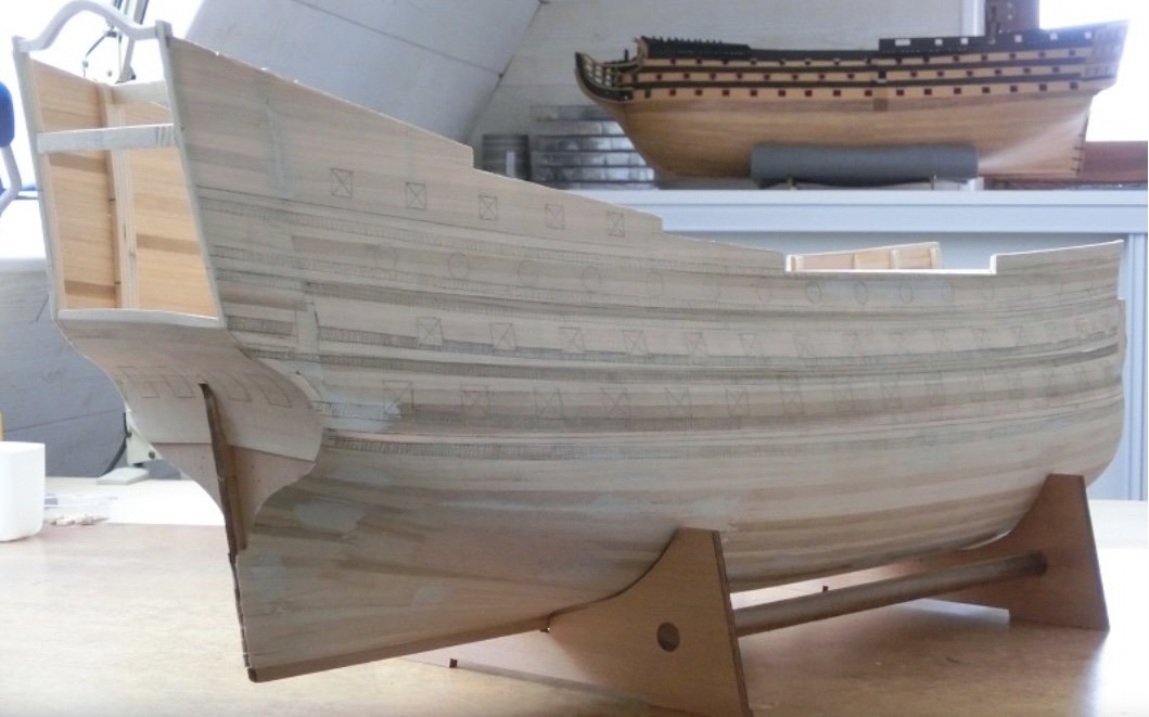
Here are a few pics of the lower hull before painting:
View attachment 131376
Above, you can see the representational forward chase port that I engraved into the plastic. This port gives me 15 lower deck piercings, which actually corresponds with her re-build configuration on the lower deck.
View attachment 131375
View attachment 131377
You can see, above, that I had to shift the aft-most port on the lower deck forward 1/4”, in order to make room for the lower finishing of the quarter gallery.
View attachment 131378
View attachment 131369
View attachment 131368
And, after priming:
View attachment 131365
This overview shot gives a sense for the eventual broadening of beam.
View attachment 131367
You can still make out the stock, outboard hawse hole, which had to be filled after adding the stem extension pieces. The whole project hinged upon the success of these extensions, which did require some careful heat-bending and re-engraving. It was a relief when it all came together.
View attachment 131366
View attachment 131371
Now, a few images while working through Herbert Thomesan’s age and distress paint protocol:
View attachment 131373
View attachment 131372
View attachment 131374
View attachment 131380
View attachment 131381
View attachment 131382
View attachment 131383
Above, you can see the interior thickening of the gun ports that I added, from the outset, in an effort to give a sense of the frame depth of a real hull. I dislike the hollow appearance of plastic warship models because they do not convey any sense of hull thickness. Here the port depth thins as you rise from the lower to middle deck. My objective is always to reduce any impression of a plastic model; to that end, all flash is eliminated, injection mould craters are filled, and surfaces are appropriately textured.

People sometimes wonder about the surface sheen of my finish. It is actually not this shiny in person. I clear-coated everything with a matte spray, that mutes the sheen without robbing the surface of all of its depth.

More to follow; next, I will post assorted upgrades to the guns, their carriages and the port lids.

Thank you for looking in!
Ich lese mit größer Sorgfalt und Bewunderung deinen Bericht.Ich habe gerade erst mit der SR begonnen und die Innenbeplankung komplett durchgeführt.
Ich habe aber eine Frage zu deiner Rumpf Nagelung. Wie hast du diese ausgeführt .
Ist das Styrol Rundstab ,und in welcher Abmessung?
Ds ist bewundernswert und ich würde es gerne bei meiner SR kopieren….
Viele Grüße aus Germany ; Bernkastel-Kues / Mosel
 
Hi Andi - I always appreciate interest and kind comments on my work. One small thing - it is a courtesy to adopt the predominant language of the forum. I really like the Google Translate app, as it does a perfect job of translating German to English and visa versa.

Yes, for the wale bolting I use .020 styrene rod. A more thorough accounting of this technique begins on page 9 of the mother log:

Hi,
Danke für deine schnelle Antwort. Leider kann ich die vorherrschende Sprache Englisch nicht in Wort und Schrift. Für mich ist die Übersetzung also der einzige Weg,international mitlesen zu können.
Ich habe mir das ab Seite 9 mit deinem Bericht angelesen und bin immer mehr sprachlos.
Aber ich habe Fragen: Wie meinst du sa ,die Styrolstücke mit Zinnfolie und einem Stabfeuerzeug herzustellen?

Könntes du das vllt. kurz etwas genauer beschreiben?
Vielen Dank und weiterhin viel Freude mit deiner SR
lg
Andi001
 
Das Schöne an der Google Translate-App ist, dass ich meine Gedanken auf Englisch formulieren kann und die App eine nahezu perfekte deutsche Übersetzung liefert, die ich kopieren und in das Build-Protokoll einfügen kann ;)

For the bolting, I use .020 Evergreen styrene rod. I use a single-edge razor blade to cut slivers that are no more than 1/64” thick (.0156). These tiny bits want to clump together on the blade. Cut a lot of them. Then, spread them out onto your heat-resistant cutting surface with the tip of a craft knife. I like the typical wand lighters that you might use to light a grill. What I mean by “flash” is to pass the flame just a few millimeters above the styrene dots. Experience will quickly teach you how quickly is too fast or too slow. You will know, though, because you will be able to see the dots transform from flat slivers to domed boltheads.

For application to the model, I use a sharpened toothpick to apply a dot of glue wherever I want a bolt-head. To make the operation a little less tedious, I generally found that you can apply three dots of glue at a time - maybe four, if you get really good at the next step. I then use the very tip of a super sharp (#11) craft knife to pick up the bolt-heads (domed surface facing up) and place them on the glue dots. I then press them down with my finger for a five-count.

I have been astonished when, at times, I have had to remove a few; they have to be shaved away with a sharp chisel because they are so firmly welded down.
 
The through-bolting along the scarf joints of the wales is a little different. For these, I have found the best method is to drill .020 holes into the bolt locations and then insert short lengths of .020 rod that I have dipped into liquid styrene cement. Don’t worry about uniformity, at first. Once the glue is dry, I just use a card sander to level the bolts to a uniform height.
 
Vi
Das Schöne an der Google Translate-App ist, dass ich meine Gedanken auf Englisch formulieren kann und die App eine nahezu perfekte deutsche Übersetzung liefert, die ich kopieren und in das Build-Protokoll einfügen kann ;)

For the bolting, I use .020 Evergreen styrene rod. I use a single-edge razor blade to cut slivers that are no more than 1/64” thick (.0156). These tiny bits want to clump together on the blade. Cut a lot of them. Then, spread them out onto your heat-resistant cutting surface with the tip of a craft knife. I like the typical wand lighters that you might use to light a grill. What I mean by “flash” is to pass the flame just a few millimeters above the styrene dots. Experience will quickly teach you how quickly is too fast or too slow. You will know, though, because you will be able to see the dots transform from flat slivers to domed boltheads.

For application to the model, I use a sharpened toothpick to apply a dot of glue wherever I want a bolt-head. To make the operation a little less tedious, I generally found that you can apply three dots of glue at a time - maybe four, if you get really good at the next step. I then use the very tip of a super sharp (#11) craft knife to pick up the bolt-heads (domed surface facing up) and place them on the glue dots. I then press them down with my finger for a five-count.

I have been astonished when, at times, I have had to remove a few; they have to be shaved away with a sharp chisel because they are so firmly welded down.
Vielen Dank für deine Ausführungen.Dies ist nun für mich gut nachvollziehbar.
Allerdings weiß ich noch nicht wo ich Deutschland Evergreen Rod Stripes in 0,25mm beziehen kann.
Keiner meiner Händler hat diesen Durchmesser auf Lager oder im Portfolio
 
For the plastic cards, how many thicknesses do you use? What material for the resin mold? I'm planning on using milliput with bits of the kit sculpture reproduced in resin for the figure head, milliput for the moldings.
 
I have styrene sheet in .015, .020, .032, .0625, and I have a multitude of styrene strip sizes and various extruded profiles (rod, L-Angle, triangle, U-channel).

I made all of the repetitive castings (fleur-de-lis, shells, port enhancements, etc) with Allumilite 2-part resin. I made casting moulds out of latex based mould-medium that you can find in any good arts and crafts store (simply pressing my master into the un-cured rubber).

The Allumilite definitely has a shelf-life. I found that after 8 months, I had to add proportionally more hardener to resin, in order to get a good cure.
 
Well, I’ve got the ocher cut-in on the port side, and I’m a third of the way through the ocher, starboard. You can’t really tape these lines because of the limited access and curved shapes:

55A4EFCD-7C1B-4E37-95E2-4B292C7630F2.jpeg
67EA8558-B59A-4A37-854B-654DC9AAC5F8.jpeg
29EEAF4F-6196-4FFE-9123-F15BC8AE0058.jpeg
There is still much to paint here. I have to grey-wash the horse and the cathead figure. I still haven’t muted the colors of the red and yellow ocher, and of course none of the gilt work has been done. Little by little, though, we are getting there.
 
Back
Top