Soleil Royal by Heller - an Extensive Modification and Partial Scratch-Build by Hubac’s Historian

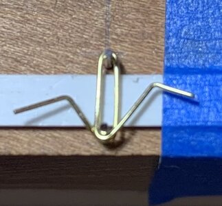
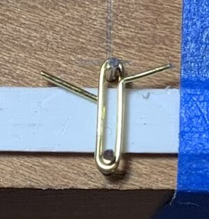
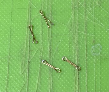
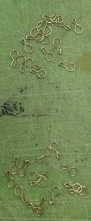
So far, I’ve made the 5MM, fore and main deadeye strops. I just completed the 3.5MM backstay deadeye strops.
IMG_5695.jpeg

Below are the rough strops before filing away excess solder. Above are the cleaned-up strops. I have adopted a method described by R.C. Anderson, where the join overlaps and is concealed beneath the channels. I’m reasonably satisfied with these. Now that I have a new pair of nippers, I will get busy making the other links, although I still need to make 4MM deadeye strops for the mizzen chains.

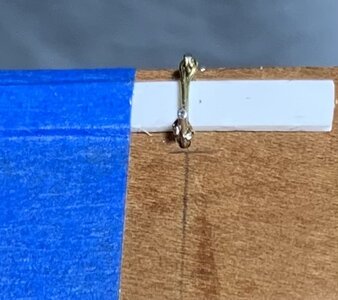
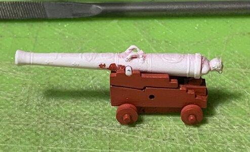
I wanted to do something more familiar and fun, so I’ve started re-locating the trunnions for the main deck battery. To the left is the stock trunnion location, and you can see that the cascabel overhangs the carriage end to an excessive degree. To the right, I’ve shifted the barrel forward to where it should be:

IMG_5696.jpeg

This process begins by shaving away the existing trunnions, and making a simple marking gauge to locate the new trunnion position:
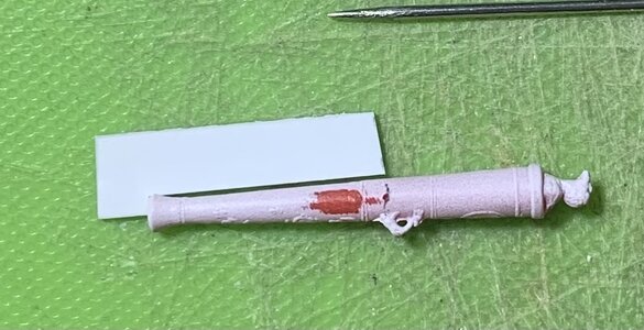
IMG_5697.jpeg

I use an awl to make a starting depression for the drill, otherwise the bit will just skate across the rounded surface. First, I chuck the bit in a pin vise to get a better bite on both locations. Then, I can chuck the bit in the Dremmel and drill though one side at a time:

IMG_5699.jpeg

A short length of .035 styrene rod is fed through the barrel, and a spot of liquid plastic cement, on the underside of each join, secures it. On my marking gauge, I inscribed a line indicating the projection of the trunnions from the barrel side. A pencil mark on the overlong trunnions gives me a reference to nip to. I clean the ends with a file, and voila:
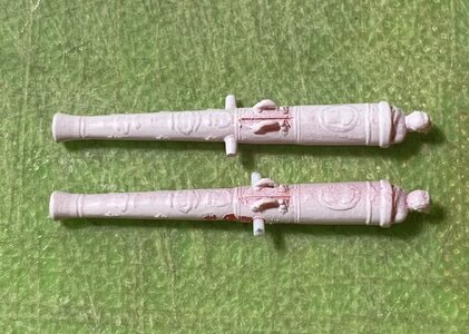
IMG_5700.jpeg
IMG_5701.jpeg

Corrected trunnions!

Ultimately, I will add either paper or foil cap squares to the visible, detailed guns.

Thanks for stopping by and looking in at This Old Project!
 
I definitely agree with you, Waldemar. It’s a little laborious, but a satisfying tedium that could have been much more involved. As you are well aware, there are other things that could be fixed, but I will be satisfied with a more correct overall impression.
 
Last edited:
.​
As the saying goes: enough is enough. I don't think many would have chosen to make even such a small upgrade (in terms of effort), but which produced such good results compared to the kit manufacturer's proposals... :)
.​
 
Well, the 6th grade CYO basketball season has drawn to a close and our team succeeded beyond my wildest dreams: we went 13-1, and captured the Manhattan division title. Our second and final loss came in a division matchup with the Bronx winners. We played a gritty first half, and kept it close, but made mistakes in the second half. We were simply overmatched. Nonetheless, it was a wonderful and extremely rewarding season. The Knicks, on the other hand, continue to surprise, so my attentions remain somewhat divided.

That being said, I am lately looking to focus more on model building. I’ve completed all of the fore, main and mizzen channel deadeye strops. Although Andre Kudin’s particular method is definitely more efficient with less clean-up - he solders the lower strop loop at a neatly cut joint - I stuck with the R.C. Anderson overlap method I had been using because the strops were coming out uniformly, nicely shaped, and strong. I will change my approach for the deadeye strops in the tops.

IMG_5203.jpeg

Next in order to be made are the chain preventer plates. One of the key differences between what I had first tried, when making the chain preventer plates, and what Andre does is that Andre bends each plate from an individual length of wire, rather than try to economize on material by wrapping a longer length of wire, many turns, around an appropriately sized former.

When you do the latter, for one thing - you may succeed in crimping the continuous loop neatly around the former, but it is nigh impossible, after parting the links to get the links off the former without pulling them all out of shape.

The other issue with parting the links in this way is that you end up with one neat flush end and a pinched end, which leads to a weaker solder joint.

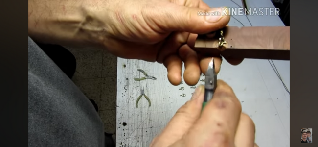
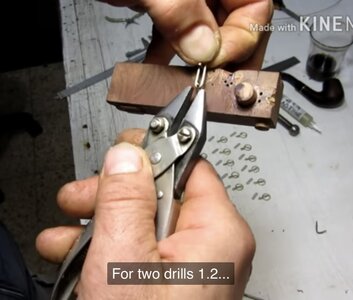
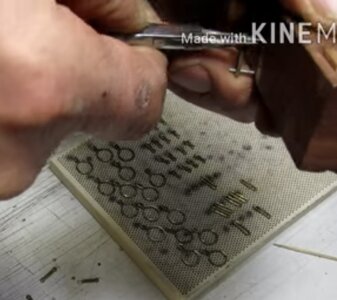
What I am after are uniformly straight chain links, free of odd kinks, and sloppy joints. To that end I set up a simple bending jig like the one I see in Andre’s videos. Following is a series of screen captures from his YouTube videos. This particular video is either #13 or #16, in the series, if I remember correctly:

IMG_5790.png
IMG_5791.jpeg
IMG_5792.jpeg
IMG_5794.jpeg
IMG_5793.jpeg
IMG_5795.jpeg

And following along, I first pre-bend short lengths of wire around a drill mandrel:

IMG_5972.jpeg

I’ve placed a shallow spacer beneath the link area, so that the ends will be slightly raised and easier to crimp with my parallel pliers:

IMG_5969.jpeg

I crimp snug around the upper pin, then use my pliers to pull each end snugly around the lower pin. I then crimp around the lower pin:

IMG_5970.jpeg

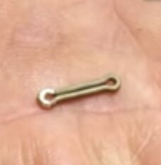
I can then remove the link, and flush-cut each side of the link. A little tweezer/finger manipulation creates a nicely closed link:

IMG_5971.jpeg

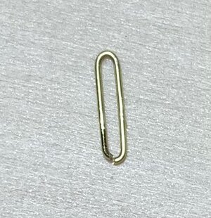
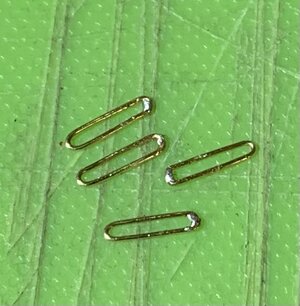
Silver solder paste has proven to be really great as I can control its application with the tip of an Exacto. A touch to the iron, and I have nicely soldered joints that only require a little cleanup:

IMG_5973.jpeg

Now, Andre puts the soldered loops back over the two-pin jig and uses his round-nose pliers to crimp eyes at each end. I found, though, that the joints with this 28 gauge wire simply failed when I tried this:

IMG_5974.jpeg

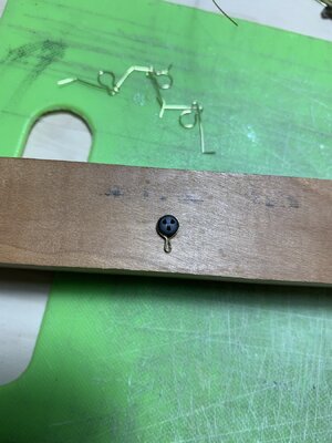
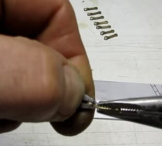
Alternatively, I found that I could place each link end over the lower pin, hold the outer end with a tweezer, and use my round nose plier to crimp around the single pin. This worked beautifully:

IMG_5976.jpeg

Now, It’s a simple matter of doing that over and again about 60X.

It is, of course tedious, but satisfying to achieve the result I am after.

More to follow!

Best,

Marc
 
Gr'at Job, Marc! Thanks for sharing your tricks. Would a softer metal not have made the work a lot easier? Or is this power eating bending nesseccary to keep the forces in place when the masts are rigged - so aluminium rod isn't of any good?
Just asking for a friend... ;-)
 
Well, the 6th grade CYO basketball season has drawn to a close and our team succeeded beyond my wildest dreams: we went 13-1, and captured the Manhattan division title. Our second and final loss came in a division matchup with the Bronx winners. We played a gritty first half, and kept it close, but made mistakes in the second half. We were simply overmatched. Nonetheless, it was a wonderful and extremely rewarding season. The Knicks, on the other hand, continue to surprise, so my attentions remain somewhat divided.

That being said, I am lately looking to focus more on model building. I’ve completed all of the fore, main and mizzen channel deadeye strops. Although Andre Kudin’s particular method is definitely more efficient with less clean-up - he solders the lower strop loop at a neatly cut joint - I stuck with the R.C. Anderson overlap method I had been using because the strops were coming out uniformly, nicely shaped, and strong. I will change my approach for the deadeye strops in the tops.

View attachment 436204

Next in order to be made are the chain preventer plates. One of the key differences between what I had first tried, when making the chain preventer plates, and what Andre does is that Andre bends each plate from an individual length of wire, rather than try to economize on material by wrapping a longer length of wire, many turns, around an appropriately sized former.

When you do the latter, for one thing - you may succeed in crimping the continuous loop neatly around the former, but it is nigh impossible, after parting the links to get the links off the former without pulling them all out of shape.

The other issue with parting the links in this way is that you end up with one neat flush end and a pinched end, which leads to a weaker solder joint.

What I am after are uniformly straight chain links, free of odd kinks, and sloppy joints. To that end I set up a simple bending jig like the one I see in Andre’s videos. Following is a series of screen captures from his YouTube videos. This particular video is either #13 or #16, in the series, if I remember correctly:

View attachment 436201
View attachment 436202
View attachment 436203
View attachment 436199
View attachment 436200
View attachment 436198

And following along, I first pre-bend short lengths of wire around a drill mandrel:

View attachment 436194

I’ve placed a shallow spacer beneath the link area, so that the ends will be slightly raised and easier to crimp with my parallel pliers:

View attachment 436197

I crimp snug around the upper pin, then use my pliers to pull each end snugly around the lower pin. I then crimp around the lower pin:

View attachment 436196

I can then remove the link, and flush-cut each side of the link. A little tweezer/finger manipulation creates a nicely closed link:

View attachment 436195

Silver solder paste has proven to be really great as I can control its application with the tip of an Exacto. A touch to the iron, and I have nicely soldered joints that only require a little cleanup:

View attachment 436193

Now, Andre puts the soldered loops back over the two-pin jig and uses his round-nose pliers to crimp eyes at each end. I found, though, that the joints with this 28 gauge wire simply failed when I tried this:

View attachment 436192

Alternatively, I found that I could place each link end over the lower pin, hold the outer end with a tweezer, and use my round nose plier to crimp around the single pin. This worked beautifully:

View attachment 436191

Now, It’s a simple matter of doing that over and again about 60X.

It is, of course tedious, but satisfying to achieve the result I am after.

More to follow!

Best,

Marc
Scratch building at its finest, HH!
 
I suppose, Chris, that copper wire would have been a little softer and more friendly to work with, but brass was readily available at my craft store, and the gauge is very light.
 
I suppose, Chris, that copper wire would have been a little softer and more friendly to work with, but brass was readily available at my craft store, and the gauge is very light.
That sounds resionable, Marc. I do look for methods I myself can work with in 1/66 - and my rods will have to be 1/3 thicker than yours. So this is very helpfull to me, too. Thanks a lot.

What is your way of fixing them to the hull? By Scratch built plastic bolts; or will you go on drilling into the hull and using brass pins then adding a plastic/resin top onto?
 
Actually, a new friend on the MSW forum turned me onto a company that makes these perfectly scaled (for this purpose) styrene rivets.

Here’s a pic of Eric’s SR as he works his way through bolting the wales:

IMG_5995.png

He special ordered a run of a couple thousand of these from a company named Eugene Toy and Hobby.

I won’t need nearly that many, and I can use them to secure the preventer plates over the next lowest chain link.
 
Actually, a new friend on the MSW forum turned me onto a company that makes these perfectly scaled (for this purpose) styrene rivets.

Here’s a pic of Eric’s SR as he works his way through bolting the wales:

View attachment 436317

He special ordered a run of a couple thousand of these from a company named Eugene Toy and Hobby.

I won’t need nearly that many, and I can use them to secure the preventer plates over the next lowest chain link.
Hello Marc,

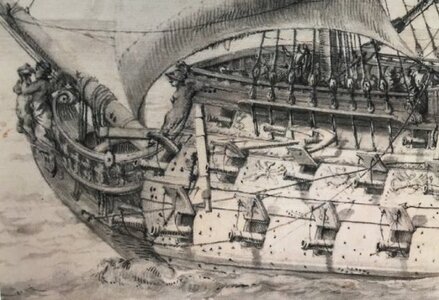
here a cut out of the well known Pierre P. drawing:

8F7C5B0D-0605-4BE6-B54E-7403916BD562.jpeg
The bolts and nails do stand apart very much from the hull's and wales's colour. For SP 1694 my own plan was to colour them in a brunt oil brown-black (adding a matt black surface with Citardel's Sepia wash). This colour appears when linseed oil is painted onto a hot iron surface, so it gives something like a deep brown glossy surface layer of it's own destingished deepness - like sugar and butter burnt in a frying pan to a very healthy biological clean candy. So there isn't this harsh rupture between light wooden colour and soth black: everything does become more a part of a harmony.
 
I think though, Chris, that while Puget makes the bolting visible in this drawing, it would not be a distinctly different shade, in real life. The French painted the whole ship, including the iron work, so actually the iron work would simply be the same color as it’s surroundings. It is just Puget’s artistic style to include these small details that would otherwise not be noticeable on the actual ship.
 
Oh Marc, I was told in some books (I do think it was Wolfram zu Mondfeld in His late "Encyclopedia of modelship building" or in

61MunvnAG1L._AC_SL1500_.jpg

"Über den Wellen bin ich einzigartig" The Sculpture Programm of ROYAL LOUIS 1668, or somewhere in
csm_technikmuseum-publikationen-schwimmender-barock-cover_5f776138bc.jpg
"Swimming Baroque" or

911QSq8NTwL._AC_UF1000,1000_QL80_.jpg

"Versailles of the Seas" -

or in the biggest book:
Cover_Schiffe.jpg

I am very sorry but I do not have have my libary at hand recently - that due to the high price of the iron work it was made visible - to show the king could even affort (the often imported higher priced metal from Styria/Austria) iron instead of wood.
 
Last edited:
That may very well be the case, Chris, but from a practical standpoint, it would seem to be counter-productive as the iron would quickly degrade in a marine environment, and the entry of the iron into the ship timbers would not be adequately sealed without a paint topcoat.
 
Well, the 6th grade CYO basketball season has drawn to a close and our team succeeded beyond my wildest dreams: we went 13-1, and captured the Manhattan division title. Our second and final loss came in a division matchup with the Bronx winners. We played a gritty first half, and kept it close, but made mistakes in the second half. We were simply overmatched. Nonetheless, it was a wonderful and extremely rewarding season. The Knicks, on the other hand, continue to surprise, so my attentions remain somewhat divided.

That being said, I am lately looking to focus more on model building. I’ve completed all of the fore, main and mizzen channel deadeye strops. Although Andre Kudin’s particular method is definitely more efficient with less clean-up - he solders the lower strop loop at a neatly cut joint - I stuck with the R.C. Anderson overlap method I had been using because the strops were coming out uniformly, nicely shaped, and strong. I will change my approach for the deadeye strops in the tops.

View attachment 436204

Next in order to be made are the chain preventer plates. One of the key differences between what I had first tried, when making the chain preventer plates, and what Andre does is that Andre bends each plate from an individual length of wire, rather than try to economize on material by wrapping a longer length of wire, many turns, around an appropriately sized former.

When you do the latter, for one thing - you may succeed in crimping the continuous loop neatly around the former, but it is nigh impossible, after parting the links to get the links off the former without pulling them all out of shape.

The other issue with parting the links in this way is that you end up with one neat flush end and a pinched end, which leads to a weaker solder joint.

What I am after are uniformly straight chain links, free of odd kinks, and sloppy joints. To that end I set up a simple bending jig like the one I see in Andre’s videos. Following is a series of screen captures from his YouTube videos. This particular video is either #13 or #16, in the series, if I remember correctly:

View attachment 436201
View attachment 436202
View attachment 436203
View attachment 436199
View attachment 436200
View attachment 436198

And following along, I first pre-bend short lengths of wire around a drill mandrel:

View attachment 436194

I’ve placed a shallow spacer beneath the link area, so that the ends will be slightly raised and easier to crimp with my parallel pliers:

View attachment 436197

I crimp snug around the upper pin, then use my pliers to pull each end snugly around the lower pin. I then crimp around the lower pin:

View attachment 436196

I can then remove the link, and flush-cut each side of the link. A little tweezer/finger manipulation creates a nicely closed link:

View attachment 436195

Silver solder paste has proven to be really great as I can control its application with the tip of an Exacto. A touch to the iron, and I have nicely soldered joints that only require a little cleanup:

View attachment 436193

Now, Andre puts the soldered loops back over the two-pin jig and uses his round-nose pliers to crimp eyes at each end. I found, though, that the joints with this 28 gauge wire simply failed when I tried this:

View attachment 436192

Alternatively, I found that I could place each link end over the lower pin, hold the outer end with a tweezer, and use my round nose plier to crimp around the single pin. This worked beautifully:

View attachment 436191

Now, It’s a simple matter of doing that over and again about 60X.

It is, of course tedious, but satisfying to achieve the result I am after.

More to follow!

Best,

Marc
Marc,
I assume these pieces are hard soldered, right? Did you try it with less paste? With this much it looks like soft soldering and the surplus paste has to be removed anyhow. Sorry, did not want to be critical (you have been doing a great job), just my 2 cents...
János
 
That may very well be the case, Chris, but from a practical standpoint, it would seem to be counter-productive as the iron would quickly degrade in a marine environment, and the entry of the iron into the ship timbers would not be adequately sealed without a paint topcoat.
I do agree absolutely on the one hand, Marc, and if the nails were only paint? In the very same way as yellow imitating gold cheaply, here black was used to imitate iron? Because on the other hand we can not discuss these dark points away in the contemporary drawing of Pierre Puget.
My decission (Edit) in this very specific spot and case would be to trust the trustworthy sources - not the logic...

....as we did find incredebly "unlogical" solutions on wrecks (much too short plank in the Osberg viking ship directly at the rudder - mentioned in: Michael Zimmermann "Das besondere Schiffsmodell" The special shipmodel).

Hth
 
Last edited:
Back
Top