Soleil Royal by Heller - an Extensive Modification and Partial Scratch-Build by Hubac’s Historian

I am also interested about which book you are talking - did not find in the last posts an info...... please !!!
 
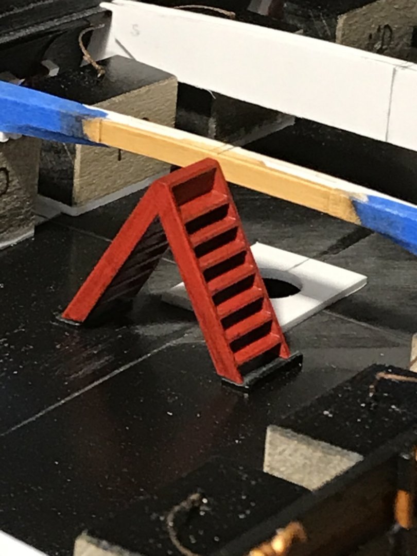
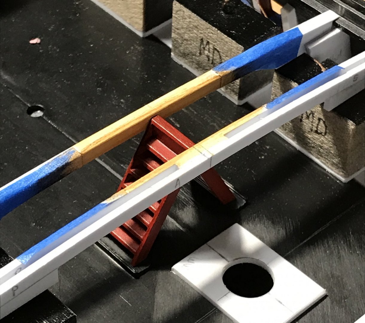
Most of the main deck beams are in. I’m still doing a little paint work on the side beams that frame the main deck companionway. As you can see, the ladders are painted and grunged-up with the walnut ink. I’ve applied the Van Dyke Brown oil over the tan base-coat of the beams. I wanted to give it a few days before applying a wipe-coat of grey wash. Once that’s all set, I’ll glue these pieces in and fair the beam tops.

C4A0C71D-3A66-482A-B587-F546A4747AE5.thumb.jpeg.fca56bccbced4321a2b045dab16a0695.jpeg

479DBEB5-3F32-4079-90C0-208FD1D0C3D0.thumb.jpeg.4ffc5063c5b1c8d9985eb2b77acf1e41.jpeg

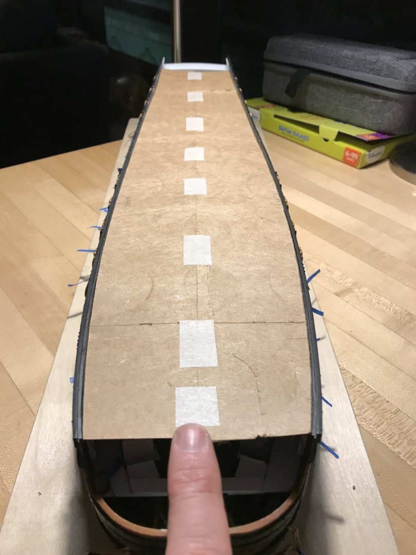
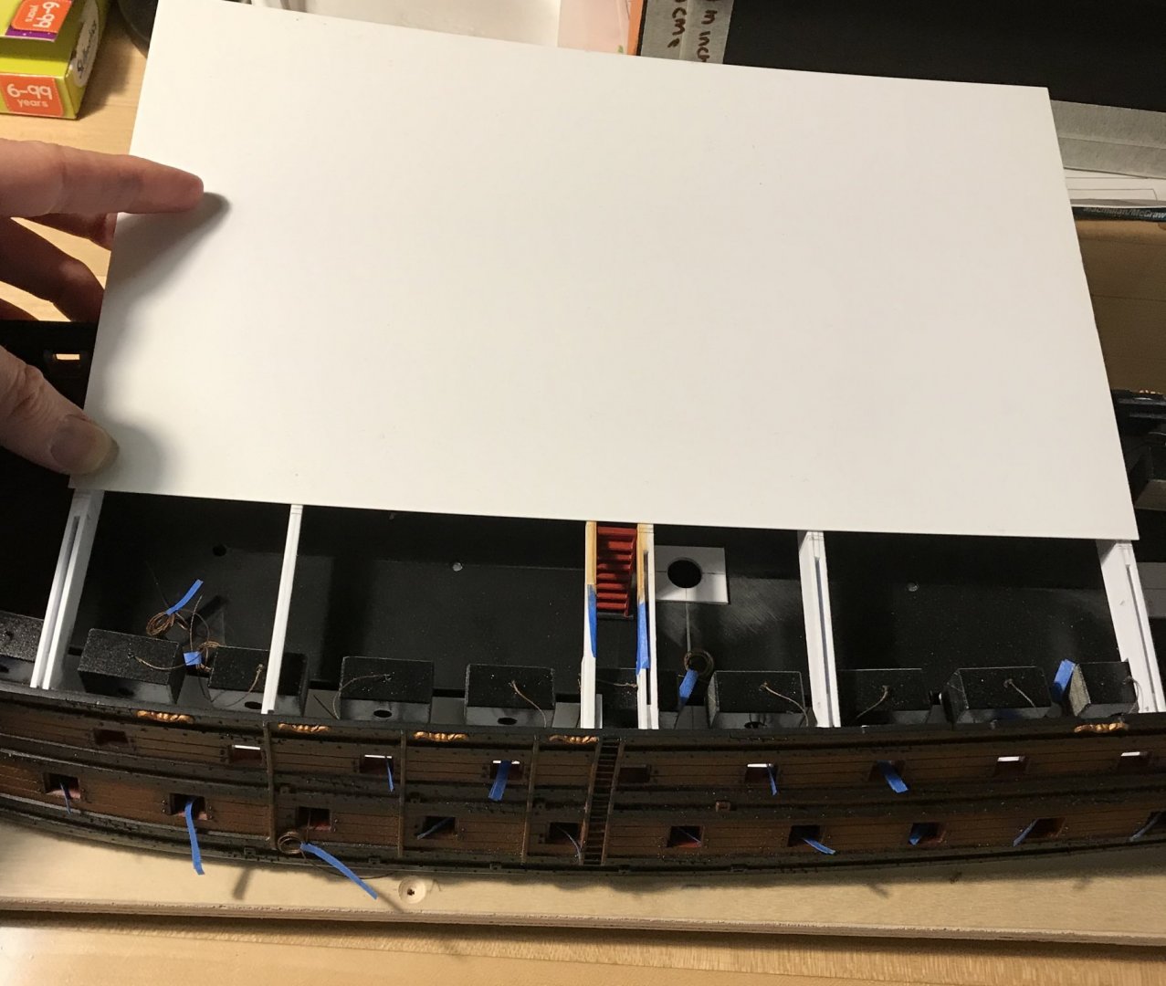
I’ve made a tight-fitting card template for the new main deck, that accounts for the differences between the port and starboard sides, as they relate to the functional centerline:

C4334113-0864-4F16-8210-623B884C8A0D.thumb.jpeg.81dea22d420570f81916075d966059dc.jpeg

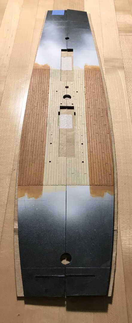
When the kit’s stock decking overlays my template, you can see just how far off the starboard side really is:

99D9366C-3D59-4F3E-BA37-69E35678306C.thumb.jpeg.de71b90e90cf7b3f322c948edb0524dc.jpeg

In the end, as long as it all looks like it fits together seamlessly, these a-symmetries won’t really matter.

I will most likely make the main deck up in three segments of 1/32” styrene sheet. I’ll have to check where, exactly, the forecastle breaks, but the standard sheet length falls just beyond what should be two good beam locations:

14066A79-2C4B-4543-AC8E-031D035C4388.thumb.jpeg.3e260d249b56c093af486343b37a9284.jpeg

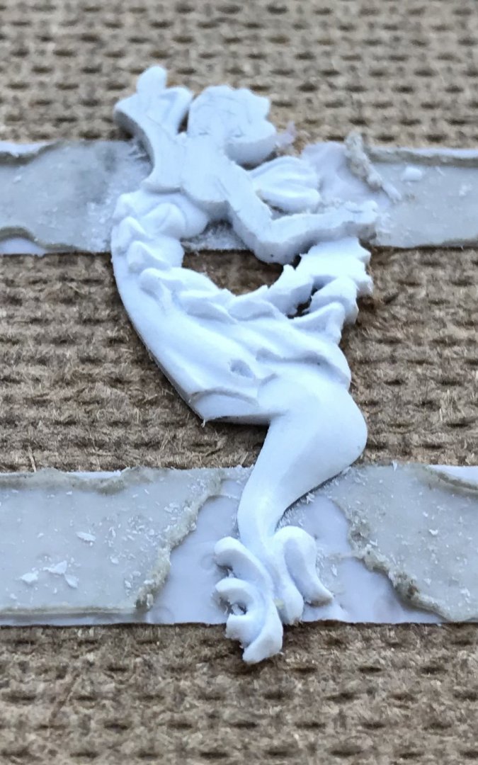
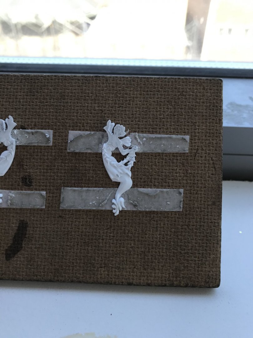
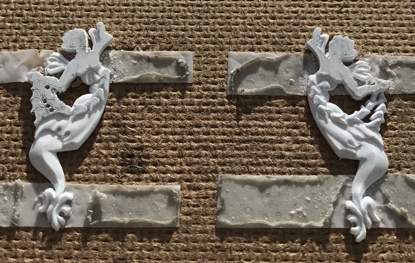
In other works, I’ve caught up on the second Mer-Angel carving and will resume work on the garland today. I desperately needed to hone the tools after all of that scraping.

Also of related, but peripheral interest is this English boatbuilder that someone else posted a link to, here, on S.O.S.:
He has a whole series of videos of him dismantling and re-constructing this 1910 pilot cutter. He manages to impart very clear explanations of function, structure, fastening and approach in an engaging way. His skill as a woodworker and boat-builder are very high, and his ingenuity in managing to safely move around such large timbers and structures is truly fascinating. If you want to better understand the fabric of wooden boats, and stave away the boredom of Pandemic, then this series is for you!

Be well
 
Last edited:
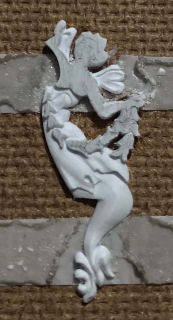
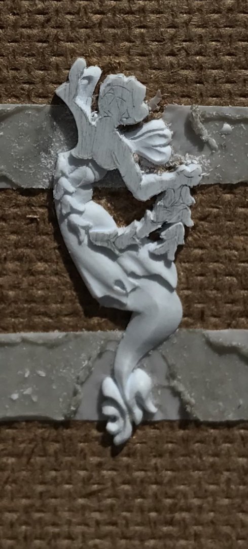
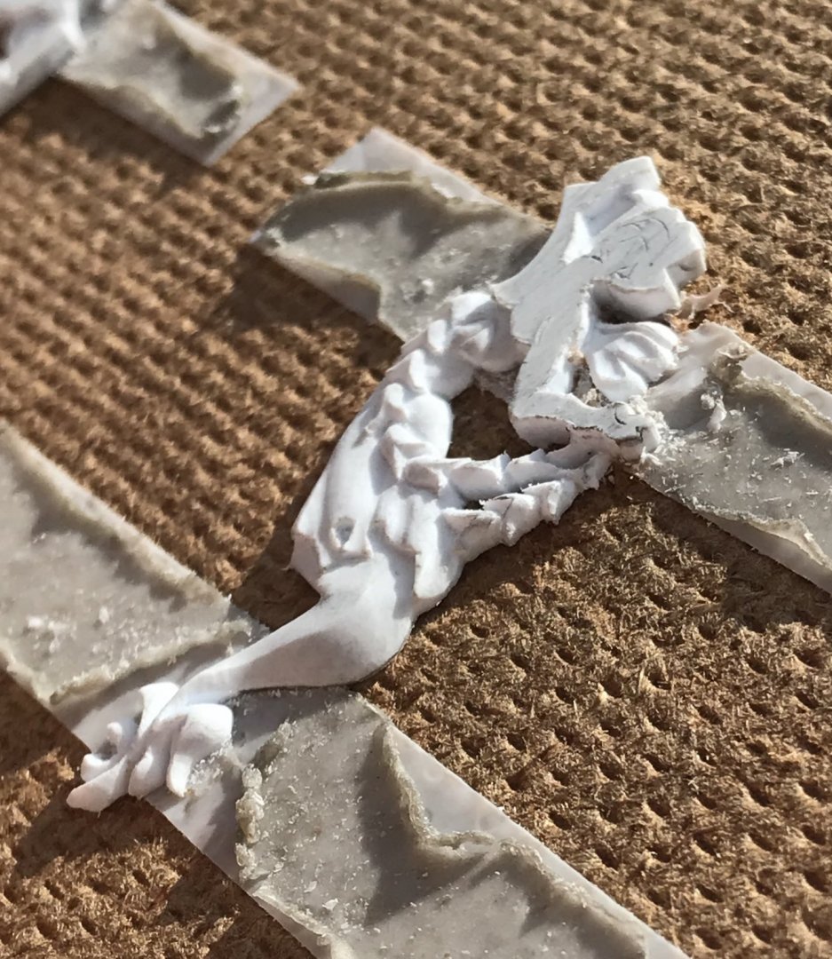
Just a quick montage of the garland. So far, I have found this to be one of the most enjoyable segments of the carving. Bellflowers look difficult to do, but you really only need the EXACTO and the hooked knife. The whole process is digging-in, paring and scraping as described, before.

Once the outlines of the flowers were really clear (digging-in and paring cuts with the BEEBE), I’d begin by parting the bell-bottom of each flower with a flaring bevel. Then, it’s a simple matter of scraping the outer bevel all around the bell-curve. What you are aiming for is to pare the points down closer to the ground, while leaving the top of each bell as the high point:

7DB44D36-2548-43FA-9F3A-64FA8CC56386.thumb.jpeg.3fb03ea07158dbcad5cac2e928dec905.jpeg

At the outset, I was a little bothered by the separation between bell flowers. As the modeling progressed, however, this seemed less glaring. In the end, because everything is so small, it becomes more an impression of the form:

D943C989-A78C-41F3-B278-3A0A5A098685.thumb.jpeg.729a8be3af22336e3ed8513fbb089690.jpeg

AA989FD2-07AD-4084-9B1B-97523847AAED.thumb.jpeg.8496f098f35a3d82227029504de4a342.jpeg

At this point - where the bellflowers separate from the body, it is necessary to taper-down the remaining garland so that the hand and arm finish as higher elements:

FCA3981E-7606-4067-BDD0-11D7AC63BCC2.thumb.jpeg.c88c47531766fa74225a7e48df0a3dd3.jpeg

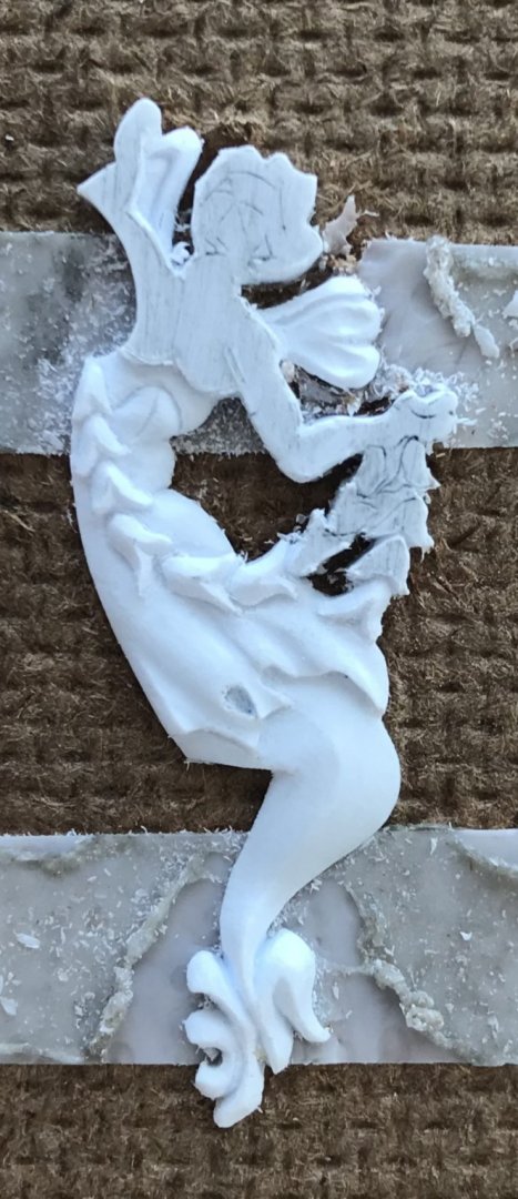
Once you have reduced the thickness of the remaining garland, here, it becomes much easier to dig-in (with the EXACTO and the tip of the BEEBE), and define the remaining bells, which become very small:

167F456B-B6D5-4B4E-8BED-1D68973E1629.thumb.jpeg.419e335ecfcbc8c4d2bf6bdb825db404.jpeg

A little bit of pencil sketching helps you to define these shapes.

08EB2B54-8768-49C5-81E1-CFDF0A3CB2CD.thumb.jpeg.b14026a5844efde2f4bfbaf65857f6d3.jpeg

A95F0EB8-7948-4EB6-942B-CC62C75AD8F1.thumb.jpeg.2d232c091721347f9d991c504860470d.jpeg

94245D67-F04F-4D11-8EFD-31BD79EE124A.thumb.jpeg.f5bb5856caf0d6f64be3b4932d054811.jpeg

04909985-0FA8-44E6-B1B7-752EE8BBAC66.thumb.jpeg.1671a7e4b7346c49127ad68c8a40bdb5.jpeg

Having solved these problems, the starboard side is proceeding much more swiftly.

Thank you for your interest!
 
Thank you, Stephen! Yes, the carving is quite small: from wing to tail tip they measure 1 1/2”.

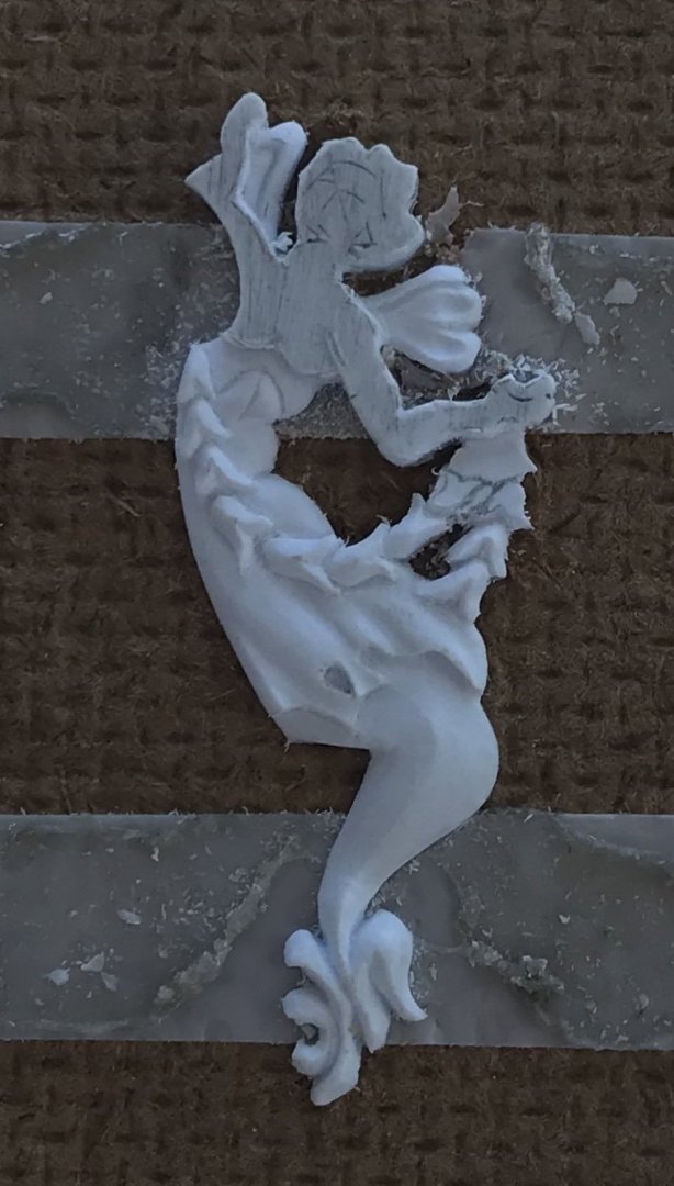
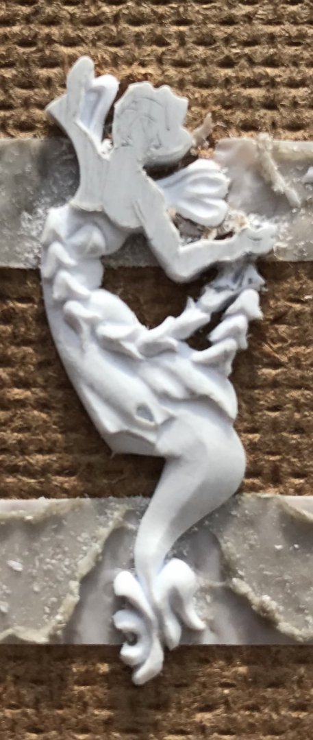
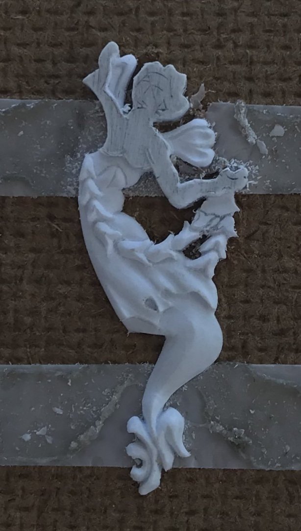
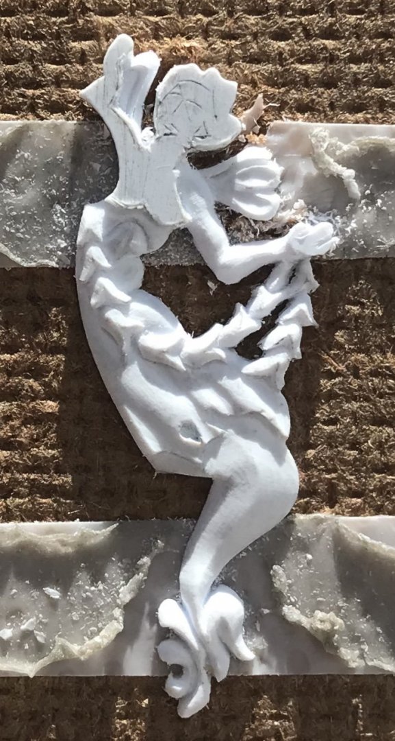
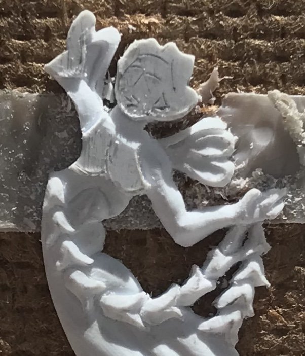
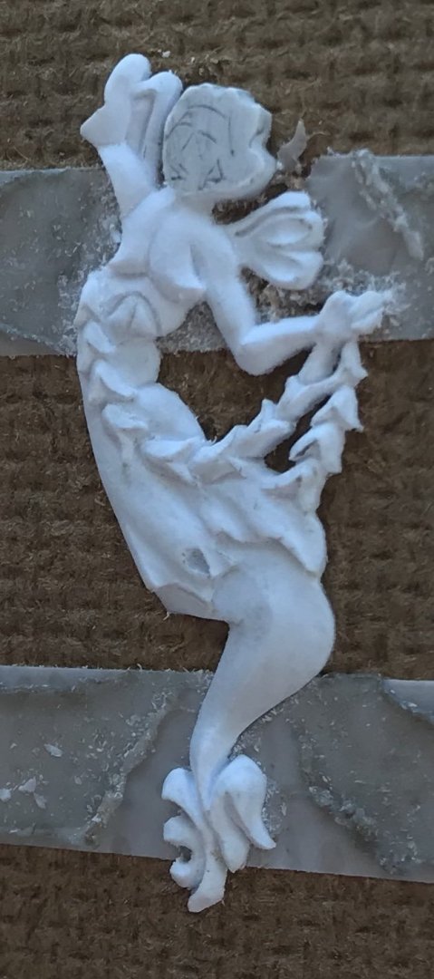
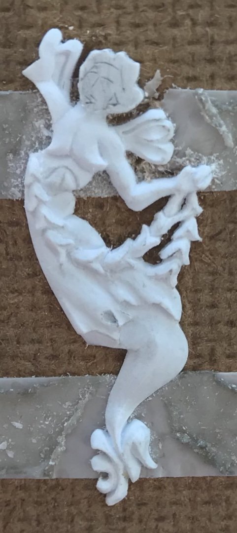
The chest and arms:

3275DF61-9C03-49C0-8366-EB247799A1B6.thumb.jpeg.1ccafed9570ba39d177c24bdd26bd9d8.jpeg


283A5C88-A230-4C7A-BA80-8D81A2AFFBEC.thumb.jpeg.618a8925f4e1f115fc36df5ead9a8bb8.jpeg
258EE63F-7194-4C2E-B445-4EE038F96CC5.jpeg.d14308f60ccf04f4757f8ee24b59ef62.jpeg


AB9E11AF-8430-48A5-A371-B66FEE4CC9FD.thumb.jpeg.049c933ba08e22e1361816735ff5b34b.jpeg

B69E78B2-2E4E-4408-BF72-6D972ECAEAEE.thumb.jpeg.1e3f0d32459d826d75b4030687533cc9.jpeg

The forearm and hand were tricky. I had to do some delicate re-shaping of the forearm because the way I cut it in, initially, looked a little squiggly. As for the hand, there’s at least the suggestion of a thumb and clenched fingers. At this scale, that’s plenty good enough.

The other arm is ill-defined, but the conceit is that most of the arm is tucked behind the crown ornament.

Well, we are almost there! I’ll catch up on the other side, and then I’ll tackle the face.
 
Superbe work Marc.Your detailed photographic account may encourage others to give it a try
I dabble in plastic modelling but nothing like this.One tip I could possibly give you is something I discovered watching countless Japanese video's on youtube.If you have any tiny toolmarks or abrasive scratches remaining,simply paint the item very quickly with a light coat of Tamiya extra thin glue and leave to dry.This removes these as if by magic but you do not loose the detail.It also removes the fine furry edges you can get when working with plastic.Sorry if I am teaching you to suck eggs

Kind Regards

Nigel
 
Marc it was a series of video's on YouTube.You can't use the search facilities on youtube as all the titles are Japanese apart from vessel names.They followed various builds mainly in 1/700.No subtitles either but they had clear shots of every product they used,you really didn't need to be fluent in Japanese to understand what they were doing.
I bought some Japanese magazines called Navy Yard through ;
The work in there is mindblowing.Again all in Japanese but the build up projects are well documented with pictures.Lots of 1/700 builds from scratch.I have ordered lots of things through 1999.co.jp as I found a lot of the best stuff,tools,detail up parts etc are unavailable outside Japan.

Kind Regards

Nigel
 
Thanks, Nigel! I will be looking into these sources with great interest. Though, I can’t name them individually, I know there are several Japanese artists that are expert at the diorama water effect - accounting meticulously for the relative scale of the vessel, and any known weather conditions for a particular scene. That is the stuff of magic to me.

Fortunately, I won’t need to create any dramatic seas. If I could even closely approximate what Philip Reed does with his jutelong seas, I would be very happy.
 
I had a quick search last night Marc.I start off with say IJN Kongo 1/700 and click on the Japanese links that appear on the right hand side as the chosen video is playing.I couldn't find the collection I had in mind though,it was a good few years ago which is why I can't just look through my youtube history.I do remember distinctly though that one of the builders had built a 1/700 Kongo (full hull kit) on the chocks in drydock with full surrounding buildings!

I think your Soleil Royal may look good anchored in calm water with possibly a Launch rowing towards her.

Kind Regards

Nigel
 
Oh, excellent, Nigel! I will give those searches a try.

I think you are right about the potential setting for my model. She will be anchored in the Brest roadstead, with the arsenal walls visible in the distance.

A launch, perhaps carrying Tourville, will be rowing up alongside the ship, as the crew makes preparation to raise anchor. I’ll have to do some research into the exact procedure for making sail, and whether it’s plausible for anyone to be boarding, as the topsails are being loosed, and the cables go slack.

These tips of yours have been very helpful. Much appreciated!
 
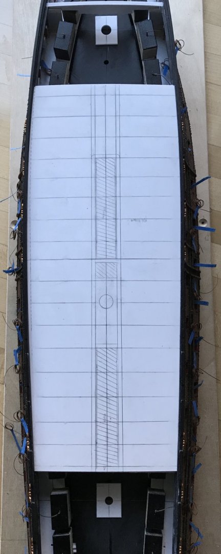
I’ve been designing the main deck and taking my cues from Lemineur’s St. Philippe monograph.

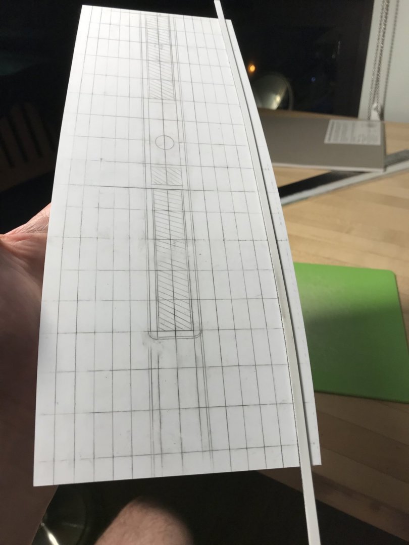
The beam locations are taken and extrapolated from the junction of the hatches:

20E4F8B3-6A2A-4116-9AC3-749470F553FD.thumb.jpeg.9be5034c578eef6555ae927c77a4a1c3.jpeg

The hatch-marked areas are the cut-outs for the hatches and companionway. To either side of the hatches will be the central pair of king planks, which are marked out.

The hatch combing will be contiguous with the central king planks, but with radius’d corners at the forward end of the main hatch, where they will drop down to the main deck level.

The main mast will have a mast plate that is flush with the combing framing. I’ll cut the opening in the base deck layer a little loose, so that I can make a final plumb on the main mast, which I found to be a little out of plumb, at the mid-deck level.

The hashed line, on the port side, is the symmetrical outline of the starboard side; I needed to use the flatter side as my baseline for laying out the tapered fore/aft planking.

The trick is figuring out the plank tapering while accommodating the second pair of king planks, with five strakes of regular planks, in-between.

I haven’t figured out, just yet, how to lay all of that out. For tonight, though, I’m satisfied with my progress.
 
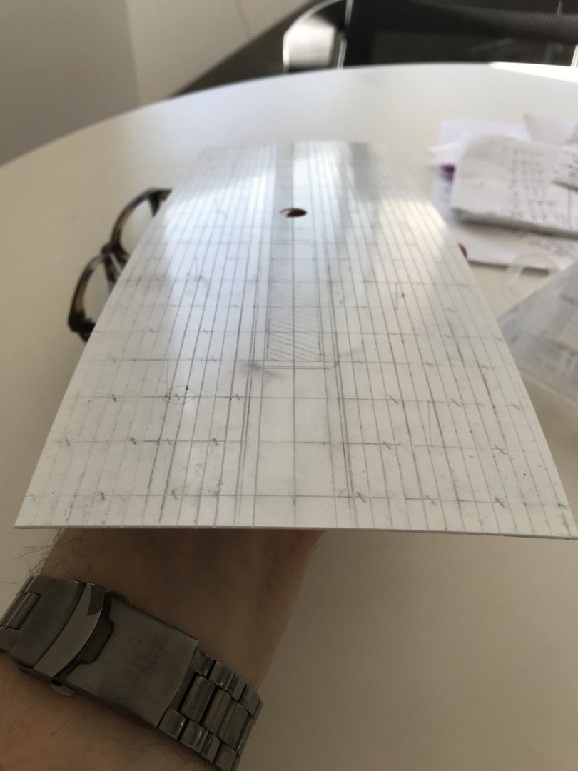
I was having the hardest time figuring out how to lay out this fore and aft tapered deck. I was stuck on the difficulty of representing the second king plank, between the central combings and the bulwarks; sure, I can divide each beam location equally, starting at the greatest breadth, by a given number of strakes - but, how do I consistently account for the slightly wider king plank, in the midst of all of that?

I could not find any subject headings in the help sections of either MSW or SOS. I was just about to cop-out and layout a parallel-straked deck of uniform width planks, when it dawned on me to begin by simply laying out uniformly tapered planks.

First I divided the port and starboard sides into two uniform belts. I further divided each belt into thirds; this simple exercise in sub-division made it so much easier to reliably tick-off equal plank widths over increasingly narrow spans.

I then applied medium tack double-stick tape to a styrene batten that I could lightly tap onto each tick mark, and then nudge into a fair curve:

667F2C64-1C9C-468E-9AF8-27817007BFD3.thumb.jpeg.6ad56e855f60ab1b1c13fbc9b93ec079.jpeg
Having gotten this far, I can see that the belts are fair and uniform from starboard to port, which allows me to further subdivide each belt into two planks, each. The deck is becoming a mess of graphite, but that won’t matter as long as the lines remain distinct long enough to get past the engraving process.

There are a few considerations, here, worth mentioning. My initial determination for the width of the hatch-combing king plank was not wide enough to account for the increased scale of my, now, wider deck. A too-narrow hatch combing would have necessitated subsequent plank divisions that would be too narrow, and numerous; more like the deck of an Iowa Class battleship.

That is the difficulty of this project. I began by increasing the width, at the stem, by a generous 5/8”, so that I could increase the width at the stern, enough for the missing sixth light. The effect these alterations had on the mid-ship breadth of the hull, however, distort the reality of what should be; my hull is significantly broader than it should be. Fortunately, in my opinion, this improves her appearance as a steady gun platform, but it does arbitrarily affect other issues of scale, like the deck planking, which then have to be finessed for visual effect. As I’ve said before: comme-ci, comme-ca - somewhere, in-between will be this model’s reality.

As things stand, now, I will have 12 strakes to either side of the combings. This isn’t exactly right, or to perfect scale, but it will look okay and the upgrade of a tapered deck validates the compromise.

Because of the A-symmetry issue, there will be an extra strake+, on the port side, but as I said earlier - the busyness of the guns will mitigate the appearance of that defect.

Before I go nuts with the cutouts, and engraving of plank lines/butts, and the build-up of the hatches, etc, I will pierce for the main mast and make absolutely sure that my functional center line is where I think it should be; if that’s off, then the whole layout has to be scrapped.

Assuming that all works out, I suspect that I can cheat a little and emphasize the second king plank by simply engraving just to the outside of the lines, where the king plank should be. This will, ever so slightly decrease the width of the adjacent planks, but maybe it won’t be so noticeable. Alternatively, I could engrave directly on my lines, but include the scarf joinery that would be present on the king planks to signal their presence.

If anyone has any references as to how to properly go about all of this, I would love to know - at the very least, for future projects.

Little by little, we are getting there. Thank you all for your support and for following this project.
 
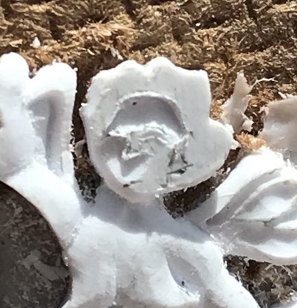
Finally - the head!

In observing Druxey’s excellent carved works for his Speedwell project, these past few days, it dawned on me that definition of the brow and position of the nose were the key determinants for getting started.

I began by digging down around the hairline, first with score cuts of the EXACTO, followed by pairing slices of the BEEBE. The idea is to approach at a steep enough angle that you creep towards the previously scribed brow line. Keep in mind that this head is just about the size of a pencil eraser head:

5CFC5127-B4CB-41C0-9CAE-9DAF54D07018.jpeg.67e9f1479b9b9d68b93cddf35d4ab8b8.jpeg

Once the hairline had been cut deeply enough, and I was satisfied with the rough slope of the forehead, I cut to the line beneath the left brow and down the nose line, setting it in relief. Again, in-between light scoring cuts, I use the BEEBE - this time with a scraping motion - to clear waste and to begin contouring the face around the eye socket.

It bears mentioning that I never intended to represent the roundness of the eye, itself.

B09D27C1-AE7D-43EB-8CD4-A3836B91AC8A.jpeg.f670064266950ffe59557f9ad3bd647c.jpeg


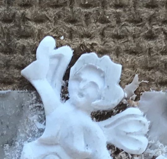
I then cut beneath the right brow, scraped waste and began contouring the cheek area with scraping cuts.

At this stage, I started to worry that I was sculpting the MerAngel of Death, and that maybe I should have her holding a scythe, because her facial features began to seem skeletal.

When the carving becomes discouraging, like this, the best thing to do is take a breath and evaluate.

After leaving it for an hour, I came back and determined that now was a good time to rough in the mouth because its presence would cue me toward how and where to shape the cheeks and chin:

4499F0C1-8E0B-4672-8B50-E976B56EBFBF.jpeg.747be089aa078e7c5af48716ea605716.jpeg


As I’ve drawn it, the mouth is just a soft diamond shape. It is achieved with four angled, stab cuts of the EXACTO, that converge at the bottom of the cut. I, then, use the heal of the EXACTO to dig out the waste and extend the corners of the mouth.

Although, in the above picture, you can see that I also began to contour the nose, I think it is evident that the simple addition of the mouth animates the face.

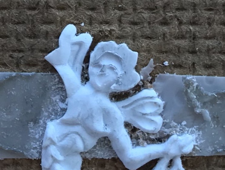
From there, it was a simple, but deliberative process of defining recesses and hollows around the cheeks and chin until the face appeared more cherubic than Skellator.

There does come a point, though, where one has to stop before they risk un-doing all that they worked so hard to arrive at. I found that point, and so I shifted my focus to shaping the coif: defined parts of the hair, rounds and hollows. it doesn’t take much to suggest the movement and shape of hair.

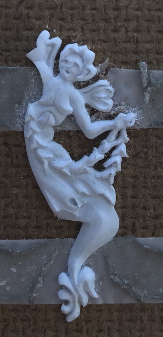
The completed figure:
44E9858C-96DA-47A7-9855-302F076B1E5D.thumb.jpeg.2844094801f87b69e3f2af99be836bcb.jpeg

I’m not 100% satisfied with the nose, but I have at least five more faces, like this, to carve for the ship, so I think I will get better at it, as I go.

Although the difference is very, very slight, you may notice that the bust profile has changed a little. A friend on the site PM’d me to offer a gentle critique. His thought was that, perhaps as I first shaped the one full breast, the end was a little too severe.

I agreed with him and attempted to soften the very end of the breast, and make it a little more natural looking. To some degree, the prior shaping of the breast limits modification, at this stage, but I do think this is a little bit better.

I want to say that I appreciate the courage it sometimes takes to offer constructive criticism - particularly when it involves matters of artistic interpretation, and most especially when it involves anatomy. We live in our bodies, full time, yet it has become increasingly difficult to talk about them without fear of offense. Anyway, I appreciated that.

So, I will complete the second carving, and then I will immediately begin the other pair of MerAngels that flank the forward edge of the quarter gallery amortisment. I have figured out what I need to modify, on these figures, so that I don’t have to eliminate my aft-most octagonal port.

It is best to launch right into more figures because the mode of seeing and thinking that it requires is now active in my mind. If I really have the stamina left, after that, I may even carve the pair of bow angels. It may be better to wait on them, though, to see exactly how all of the elements of the head come together.

In other news, I have completed my main deck layout and begun engraving the plank seams. Now that I can see the entire layout, I really am not that bothered by the extra plank+, on the port side. I remembered that there’s a plank companionway, above the waist guns, that bridges the forecastle and quarter decks.

I also enlarged the main mast hole, in the main deck just enough so that I could plumb the mast perfectly. The mast plate, between the coamings, will be a tight fit and will secure the plumb position of the mast.

Onward and upward! Thanks for looking in.
 
Last edited:
Thank you, kindly, Stephen!

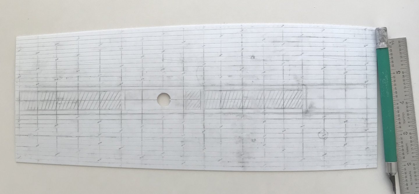
Main deck engraving is complete. With the way the plank lines faired out, the extra port plank really won’t be noticeable at all because the narrowed ends will be covered over by the quarter and f’ocsle decks:


What I really enjoyed about this particular scratch-built portion of the project is that arriving at a deck layout requires you to think like a shipwright. Although I may not be laying planks individually, my shift pattern still has to make sense.

As will increasingly become the case, I took my cues from Lemineur’s St. Philippe, and I arranged for two belts of five planks each; five between the coamings and the binding strakes, and five from the binding strakes to the bulwarks.

The coamings and binding strakes consist of scarfed planks of 30’ scale feet, and the regular plank is scaled to lengths of 24’. Please note that the coamings are not yet in place because they will be applied a few steps from now. My objective was to stagger the scarf joints, among the coamings and binding strakes, so that no two scarfs landed on the same beam.

I then chose to go with a three-plank shift of butts for the regular planking. That worked out neatly because the pattern repeats on the fifth plank. The deck is still messy with graphite, and the engraved butts may not be so easily apparent, but they are indicated by hash marks:


My objective with the regular planking was to not have a plank butt land right next to a scarf butt. I began with the port side and this was not an issue.

Then, I laid out the starboard side. I checked and re-checked the shift pattern to make sure it was correct. To note: the second belt of five planks was layed-out so that the first plank was the continuation from the fifth plank of the first belt.

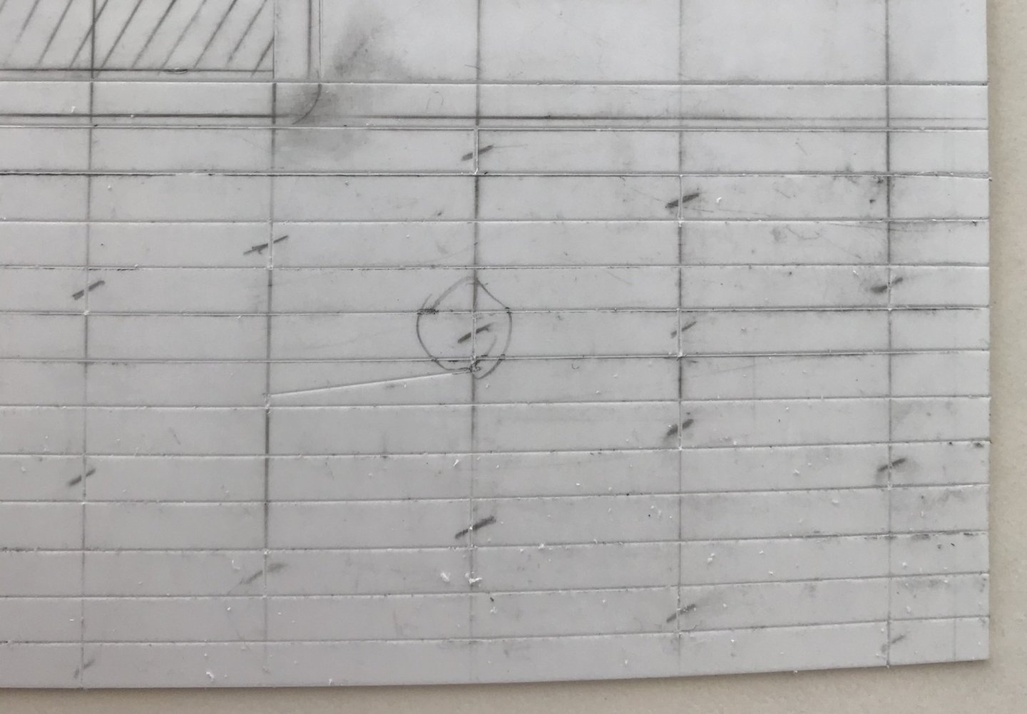
All seemed well, until I started engraving butts, from fore to aft. That’s when I noticed this problem (circled):


While this layout error did not occur on the port side, it seemed to me that I couldn’t leave this mistake. I decided to shift that one butt - that lands in the same place at every binding strake scarf - one beam forward. I’ll fill this first one with putty, but you can see that I already engraved the corrected butt, to the right.

While this disrupts my shift pattern, ever so slightly, only the most astute rivet-counter would ever notice. On the other hand, a plank butt directly adjacent to a scarf butt would jump out at anyone looking with moderate intensity. Perhaps the wiser layout would have been to mirror one whole side to the other, but what’s done is done. It’s a correction that I can live with.

Next, I’ll sand the deck with 50 grit paper. I think that my earlier deck samples could have been improved if the texturing of the deck had been more aggressive; the deeper scratches will catch more of the Van Dyke Brown, and grey distress wash.

Following the sanding, I will build up the coamings, gratings and main mast plate. Lastly, I will drill the deck for trunnel impressions, and then mount the knight heads before painting.

Happy Fathers’ Day to all!
 
Back
Top