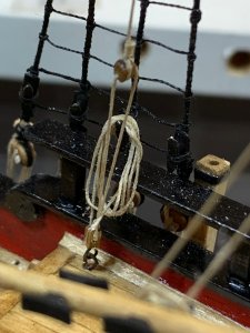
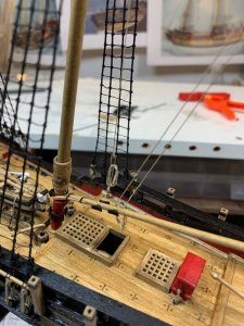
Exceptional Details !
-

Win a Free Custom Engraved Brass Coin!!!
As a way to introduce our brass coins to the community, we will raffle off a free coin during the month of August. Follow link ABOVE for instructions for entering.
-

PRE-ORDER SHIPS IN SCALE TODAY!
The beloved Ships in Scale Magazine is back and charting a new course for 2026!
Discover new skills, new techniques, and new inspirations in every issue.
NOTE THAT OUR FIRST ISSUE WILL BE JAN/FEB 2026
You are using an out of date browser. It may not display this or other websites correctly.
You should upgrade or use an alternative browser.
You should upgrade or use an alternative browser.
Sultana - Colonial Schooner, 1767 - by MS, Scale 1:64 [COMPLETED BUILD]
- Thread starter moreplovac
- Start date
- Watchers 24
Exceptional Details !
Thanks Donnie..
- Joined
- Mar 20, 2019
- Messages
- 3
- Points
- 8
Hallo moreplovac
Grossartig!
Gruss Peter
Grossartig!
Gruss Peter
Hallo moreplovac
Grossartig!
Gruss Peter
Hi Peter,
Vielen Dank
Your details are looking very good - and very good photos ! Do you have a new camera? 

Your details are looking very good - and very good photos ! Do you have a new camera?
Actually yes i do. It is a new iphone but the pictures of the completed model will be taken with my old DSLR..
Cheers.
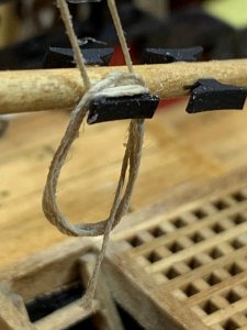
So to finish up mounting the anchor, the anchor rope has to be added.
First i laid the rope without thinking about other rope end that has to go thru gratings...
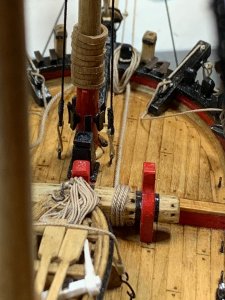
Then i remove the rope and tied it up again, in different direction.. At the same time i corrected the rope coil to rest on the anchor rope. Before the anchor rope was going thru the rope coil.. Not sure how
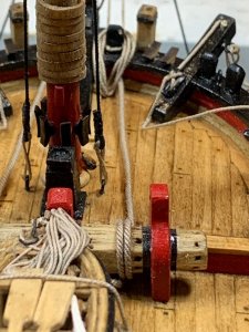
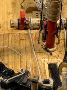
Now it looks more appropriate.
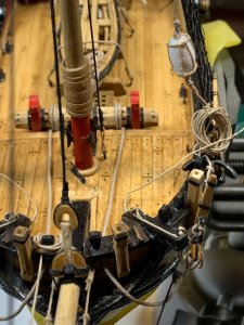
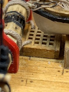
First i laid the rope without thinking about other rope end that has to go thru gratings...

Then i remove the rope and tied it up again, in different direction.. At the same time i corrected the rope coil to rest on the anchor rope. Before the anchor rope was going thru the rope coil.. Not sure how


Now it looks more appropriate.


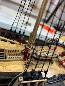
Then i spent some quality time making other rope coils; here is end result of the coil mounted on the ship..
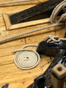
So, how did i got here?
There were few other forum topics explaining the technique to make a coil rope. Since i will need only two, small ones, i decided to make my own technique. It is simple and does the job quickly. I will definitely use some other ways once i need to make more larger coils and in a bigger number...
First, a pin was pushed thru the piece of spare wood. The wood was cut to allow the rope to pass thru.
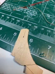
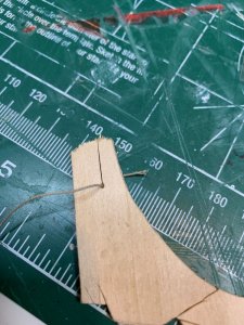
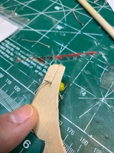
Then the pin was secured in a wise and the coiling process begun..
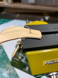
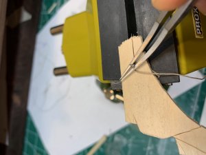
I used tweezers to hold the coil and to prevent it from unwrapping. After few circle runs, glue was applied to the coil to freeze it.. and the pin was removed.
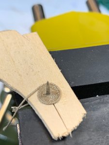
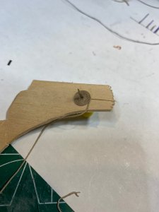
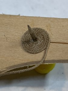
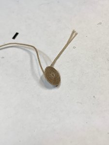
Then the coil was glued to the ship, first making sure i will be able to hide the end piece of rope so the transition with other rope end is smooth and not visible to a naked eye..
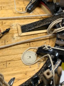
Small amount of glue was applied on the outer edge of the coil to have the rope glued, in the attempt to make it a part of the same coil..
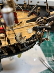
The end result is very realistic...
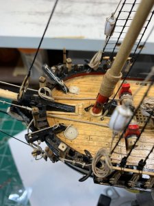
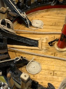
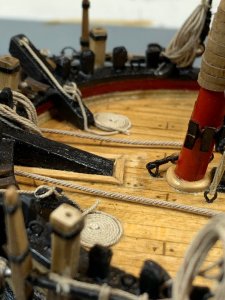
Happy modeling..

So, how did i got here?
There were few other forum topics explaining the technique to make a coil rope. Since i will need only two, small ones, i decided to make my own technique. It is simple and does the job quickly. I will definitely use some other ways once i need to make more larger coils and in a bigger number...
First, a pin was pushed thru the piece of spare wood. The wood was cut to allow the rope to pass thru.


Then the pin was secured in a wise and the coiling process begun..


I used tweezers to hold the coil and to prevent it from unwrapping. After few circle runs, glue was applied to the coil to freeze it.. and the pin was removed.


Then the coil was glued to the ship, first making sure i will be able to hide the end piece of rope so the transition with other rope end is smooth and not visible to a naked eye..

Small amount of glue was applied on the outer edge of the coil to have the rope glued, in the attempt to make it a part of the same coil..

The end result is very realistic...


Happy modeling..
After same time adapting to the new work place, a bit of free time allowed me to work on the ship.
In the same fashion as marked in the Practicum, i had to replace all dowels provided in the kit. Most of them were warped and pretty much useless. The boom was completed sometime ago. The dowel was shaped by measuring the diameter on few reference points from the plan. The final tapering was done by hand... Then the jaws for the boom were traced from plan and glued to the boom and final jaws shaping was done afterwards. The holes thru the jaws was drilled after the boom was completed, very carefully as wood can split. So start with tiny drill bit, don't use Proxxon, do it by hand, and progressively make the hole wider with different drill bit size. A bit time consuming but what the heck, it is a hobby.. The holes are used to hold parral beads, used to provide smooth move for the boom with less friction on the main mast...
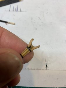
The boom ready for assembly..
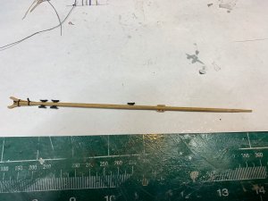
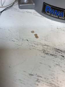
I was searching online for breads that are appropriate in size and shape to be used on the boom. Was able to locate some available in the amount of 1000 per bag, which i think it will be too much for this project so i decided to make my own. Could not find a use for 993 remaining... They will not be fully rounded, rather in the shape of a tire and i think close enough for this application. First, one tootpick was picked from the pile that had the best shape. Then using a custom made size template (two nails and a piece of scrap wood) i cut about 10 of them, in the length of 1.5mm. The sanding took place to remove any strings and to bring the beads in appropriate shape.. Using a Proxxon (as a mater of fact any other drilling tool will do the work) i drilled hole thru the appr. center of each bead.
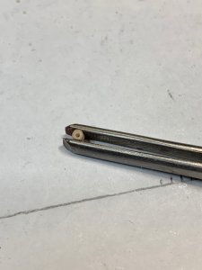
During this process some of beads just flew somewhere off my work bench - that is why more were cut....No way i will be able to find them..
Then the string was run thru them and whole assembly was painted in flat black.
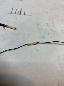
The boom ready to be mounted...
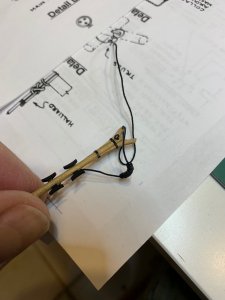
The boom was left in natural color, not painted, just stained in Golden Oak like the rest of the wood..
Before mounting i fixed all mast hoops up on the mast since they are sitting on the top of the boom jaws...
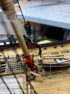
Then the other end of the rope with beads was run thru the holes of the jaws and secured with touch of glue on the top of the jaws and rope was bent and forced to the jaws. This way the rope beads does not stick up from the jaws....
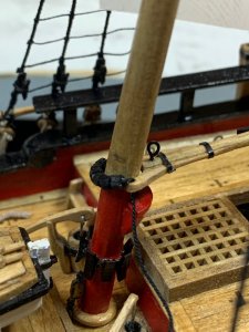
The excess rope was cut and secured with a glue on the bottom of the jaws as well. Not sure what others will do but i decided not to make a knot on the beads rope since it will bring the boom up and boom will not rest properly on the mast.
The hoops were released and rested on the top of the boom..
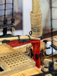
So if you come very close you might noticed that beads are not rounded but looking from a normal distance i dont think this will be an issue.
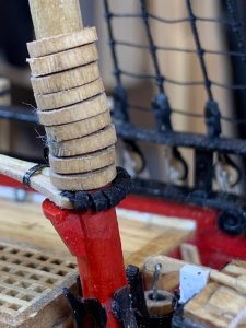
From the opposite side...
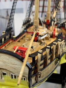
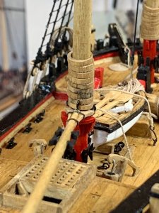
Then i seized a 4mm double block around the boom in preparation for a boom sheet assembly..
Since i forgot to install this block ahead of time, i had to lift a boom in order to get more room for tools and hands... Just watch for these small gotchas..
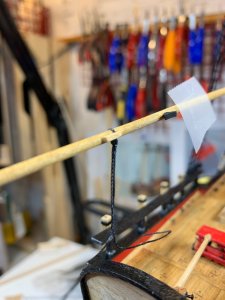
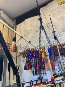
And completed...
Waiting for other tasks...
Happy modeling..
In the same fashion as marked in the Practicum, i had to replace all dowels provided in the kit. Most of them were warped and pretty much useless. The boom was completed sometime ago. The dowel was shaped by measuring the diameter on few reference points from the plan. The final tapering was done by hand... Then the jaws for the boom were traced from plan and glued to the boom and final jaws shaping was done afterwards. The holes thru the jaws was drilled after the boom was completed, very carefully as wood can split. So start with tiny drill bit, don't use Proxxon, do it by hand, and progressively make the hole wider with different drill bit size. A bit time consuming but what the heck, it is a hobby.. The holes are used to hold parral beads, used to provide smooth move for the boom with less friction on the main mast...

The boom ready for assembly..

I was searching online for breads that are appropriate in size and shape to be used on the boom. Was able to locate some available in the amount of 1000 per bag, which i think it will be too much for this project so i decided to make my own. Could not find a use for 993 remaining... They will not be fully rounded, rather in the shape of a tire and i think close enough for this application. First, one tootpick was picked from the pile that had the best shape. Then using a custom made size template (two nails and a piece of scrap wood) i cut about 10 of them, in the length of 1.5mm. The sanding took place to remove any strings and to bring the beads in appropriate shape.. Using a Proxxon (as a mater of fact any other drilling tool will do the work) i drilled hole thru the appr. center of each bead.

During this process some of beads just flew somewhere off my work bench - that is why more were cut....No way i will be able to find them..

Then the string was run thru them and whole assembly was painted in flat black.

The boom ready to be mounted...

The boom was left in natural color, not painted, just stained in Golden Oak like the rest of the wood..
Before mounting i fixed all mast hoops up on the mast since they are sitting on the top of the boom jaws...

Then the other end of the rope with beads was run thru the holes of the jaws and secured with touch of glue on the top of the jaws and rope was bent and forced to the jaws. This way the rope beads does not stick up from the jaws....

The excess rope was cut and secured with a glue on the bottom of the jaws as well. Not sure what others will do but i decided not to make a knot on the beads rope since it will bring the boom up and boom will not rest properly on the mast.
The hoops were released and rested on the top of the boom..

So if you come very close you might noticed that beads are not rounded but looking from a normal distance i dont think this will be an issue.

From the opposite side...


Then i seized a 4mm double block around the boom in preparation for a boom sheet assembly..
Since i forgot to install this block ahead of time, i had to lift a boom in order to get more room for tools and hands... Just watch for these small gotchas..


And completed...

Waiting for other tasks...

Happy modeling..
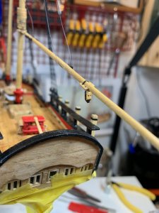
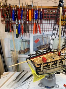
The topping lift was next. First i seized a 3mm single block to the end of not that long black rigging line. I am running out of this rigging line so have to plan every single cm... The place where i purchased these from are not making them in black anymore.
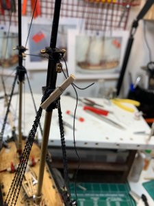
The other end of the rope was seized to the eye bolt on the cap. The length of the topping lift was adjusted according to the plan and it should be app 4cm from the boom. The tackle for the topping lift was rigged with tan rigging line (.008).
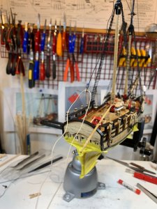
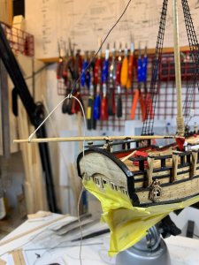
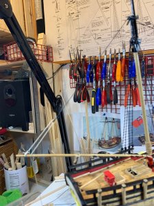
After running the rope end thru the boom it was belayed to the cleat on the boom. The complete assembly included a rope coil..
The running end was belayed to the pin on the double block which was seized to the traveler. It took me some time to do this task as the work area is not that generous in space but freezing the end of the rope and use of the small tweezers did the trick. The small rope coil was hung on the pin after all is assembled.
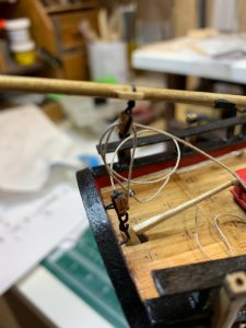
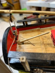
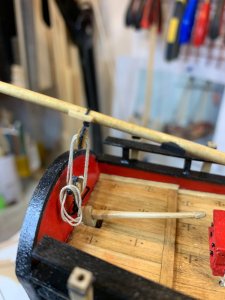
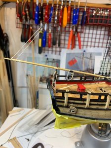
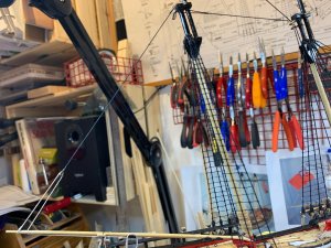
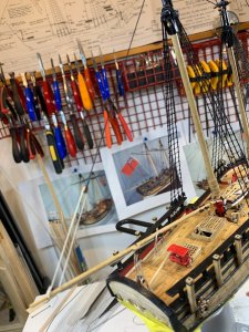
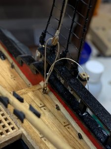
Then the footrope was attacked. I was not able to tight the knots on the same distance apart so i decided to use a smaller rope diameter to make knots.
The footrope was stretched to make knotting job a bit easier.
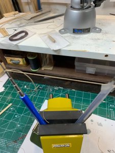
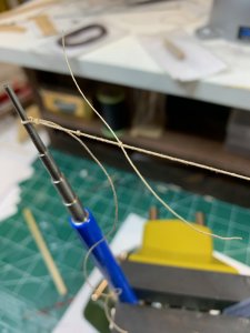
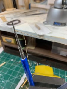
End i noticed that tomorrow is a working day so had to stop this exercise... More to come..
Happy modeling.

The other end of the rope was seized to the eye bolt on the cap. The length of the topping lift was adjusted according to the plan and it should be app 4cm from the boom. The tackle for the topping lift was rigged with tan rigging line (.008).


After running the rope end thru the boom it was belayed to the cleat on the boom. The complete assembly included a rope coil..
The running end was belayed to the pin on the double block which was seized to the traveler. It took me some time to do this task as the work area is not that generous in space but freezing the end of the rope and use of the small tweezers did the trick. The small rope coil was hung on the pin after all is assembled.


Then the footrope was attacked. I was not able to tight the knots on the same distance apart so i decided to use a smaller rope diameter to make knots.
The footrope was stretched to make knotting job a bit easier.


End i noticed that tomorrow is a working day so had to stop this exercise... More to come..
Happy modeling.
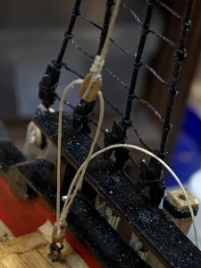
The foot rope has been completed and installed. The knots are done separately by knotting thinner rope over the main rope. I was unable to make all knots in the correct distance by just making knots with the main rope. Have no much to say today, just pictures...
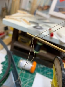
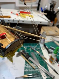
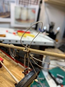
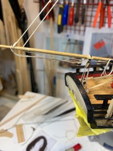
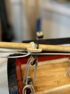
Had to resize the holes that foot rope goes thru since both ropes have to use the same opening...
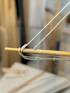
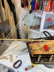
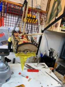
Happy modeling..


Had to resize the holes that foot rope goes thru since both ropes have to use the same opening...


Happy modeling..
Outstanding Methods and Techniques !!!
Thanks, much appreciated.
The construction of main and fore gaff has started. First the measurements were taken from the plan...
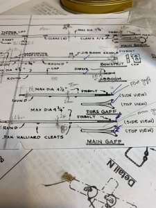
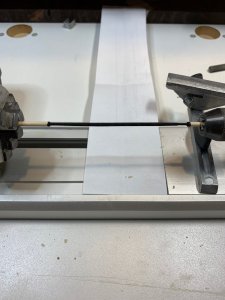
Then the gaffs were made on the lathe...
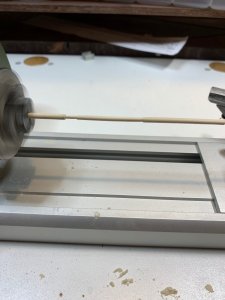
The gaffs were colored before cutting them from the lathe...
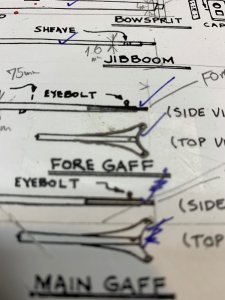
Then the making of giff end (not sure what is the correct term) was started by tracing its shape to the scotch tape...
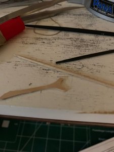
Then, the scotch tape was put on the piece of wood, and the shape was cut. The final adjustments and mounting yet to come..
More to come...

Then the gaffs were made on the lathe...

The gaffs were colored before cutting them from the lathe...

Then the making of giff end (not sure what is the correct term) was started by tracing its shape to the scotch tape...

Then, the scotch tape was put on the piece of wood, and the shape was cut. The final adjustments and mounting yet to come..

More to come...
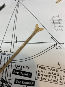
Next step was to cut a small grove for a jaws by positioning the gaff into wise and cutting the grove in very slowly pace. To make it a bit stronger i wrapped around gaff a small piece of scotch tape. If anyone has more efficient idea of how to cut this grove pls share it... I have one more to make...
The jaws were slide in the grove and glued.
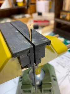
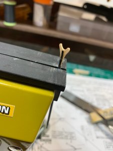
A little bit of sanding was applied on the whole construction to make it smoother..
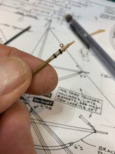
Then an "iron" bands made out of electrical tape, were cut and positioned. I also added small amount of glue to make sure those "iron" band will stay put.
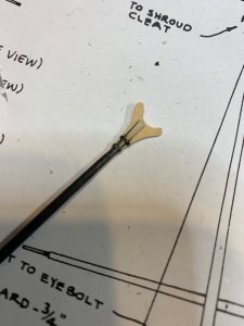
Then i made a small hook, drilled a hole for it in the gaff, started to push the hook in, and ..... snap.
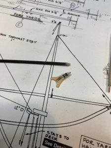
A bit too much pressure to install the hook not realizing that small amount of glue applied on both ends of the hole, started to stiffen already...
OK, well, trying to glue a jaws back on the gaff was not quite an option in this case. Before I already made few extra gaffs on lathe in longer length so used one of spares. The jaw was refurbished by removing all traces of old gaff, sanded it a bit and mounted on the new gaff.
The iron band and hook were next, making sure that glue does not cure before hook is mounted. That extra wire was sanded on opposite side of a jaws.
The layer of flat black was added afterwards..
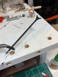
Small holes for the parral beads were also drilled through the jaw ends..
Happy modeling.
The jaws were slide in the grove and glued.


A little bit of sanding was applied on the whole construction to make it smoother..
Then an "iron" bands made out of electrical tape, were cut and positioned. I also added small amount of glue to make sure those "iron" band will stay put.

Then i made a small hook, drilled a hole for it in the gaff, started to push the hook in, and ..... snap.

A bit too much pressure to install the hook not realizing that small amount of glue applied on both ends of the hole, started to stiffen already...
OK, well, trying to glue a jaws back on the gaff was not quite an option in this case. Before I already made few extra gaffs on lathe in longer length so used one of spares. The jaw was refurbished by removing all traces of old gaff, sanded it a bit and mounted on the new gaff.

The iron band and hook were next, making sure that glue does not cure before hook is mounted. That extra wire was sanded on opposite side of a jaws.

The layer of flat black was added afterwards..

Small holes for the parral beads were also drilled through the jaw ends..
Happy modeling.
Fore gaff construction completed; well at least building part. Now blocks, rope, etc have to be installed.
First the shape of a jaws was traced on piece of wood, cut and sanded..
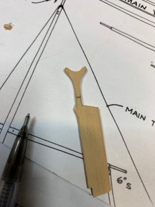
Attached to the giff, iron band installed and hole drilled.
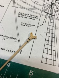
The eye bolt mounted as well. This time no snap effect..
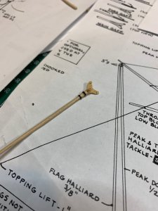
Painted in flat black... Ready for a next step.
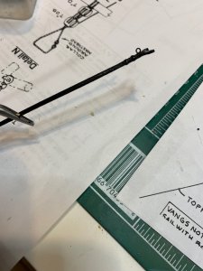
Happy modeling.
First the shape of a jaws was traced on piece of wood, cut and sanded..

Attached to the giff, iron band installed and hole drilled.

The eye bolt mounted as well. This time no snap effect..

Painted in flat black... Ready for a next step.

Happy modeling.
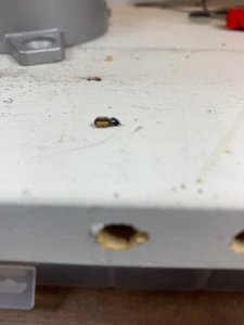
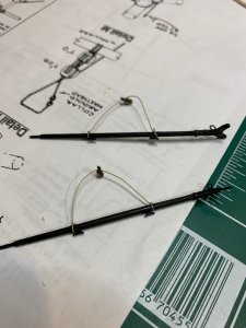
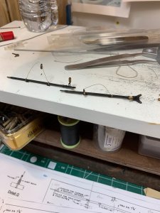
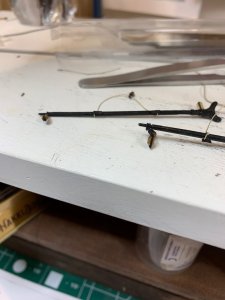
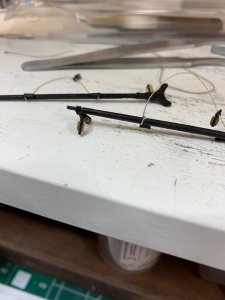
Parral beads were simulated in the same way as for the boom. The beads were cut from the toothpick, the hole was drilled thru the center, the line was put thru and they were painted flat black..
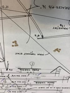
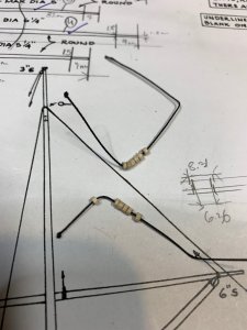
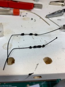
The beads were also sanded close to rounded shape...
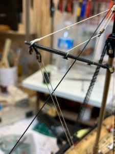
The tackles were made for throat halliard and for throat downhaul...
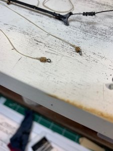
Peak halliard line was made starting with a eye....
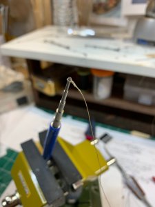
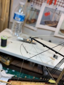
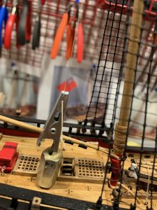
The main gaff was mounted and the lines were covered with a white glue, diluted heavily with water, to stiffen the lines and to make them straight..
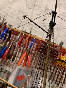
To help with straightening, the home made alligator clip was used...
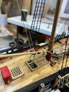
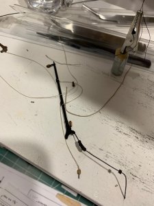
The fore gaff waiting for installation...
Happy modeling..


The beads were also sanded close to rounded shape...
The tackles were made for throat halliard and for throat downhaul...

Peak halliard line was made starting with a eye....

The main gaff was mounted and the lines were covered with a white glue, diluted heavily with water, to stiffen the lines and to make them straight..

To help with straightening, the home made alligator clip was used...

The fore gaff waiting for installation...

Happy modeling..
Work on fore gaff continues...
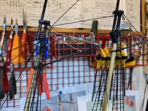
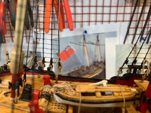
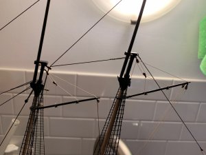
To stiffen the line and to have it look tighten, i diluted white glue 1 part glue 8 part water, using a brush i put some amount of watered glue to the line. Home made weight was connected with a piece of rope (tiny black line at the top of fore gaff) to make sure gaff stays tighten while glue dries..
Happy modeling.
Looking very good - step by step you are reaching the final finishing works


