Swan Class – ¼” Scale - Stuglo [COMPLETED BUILD]

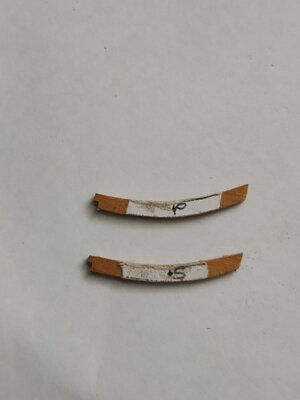
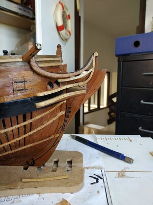
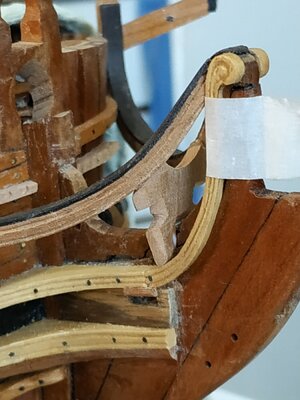
The False Rail
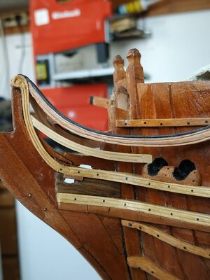
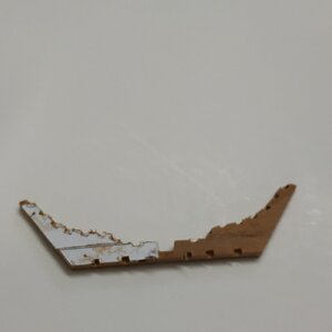
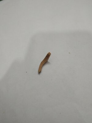
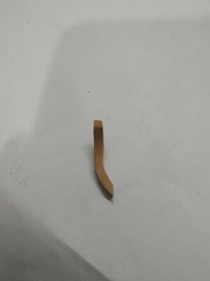
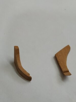
Shaped board-like structure fixed to the curve of the Main Rail
Inboard flat, outboard paneled effect.The inner face flush with the Main Rail Lining.
Thickness, 2.12 mm with groove recess 0.53
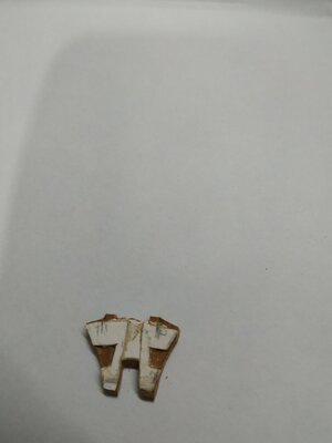
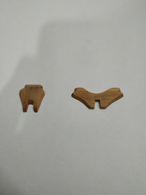
I didn’t feel able to make this recess at a constant depth, so I made a composite of 3 pieces:
Base of 1.6mm, a surround of 0.53mm and an insert of 0.53mm
(the Hornbeam blackwood is brittle and cutting part cross-grain caused the need for some repair after it was stuck to its base)

231022.jpg
 
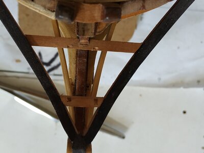
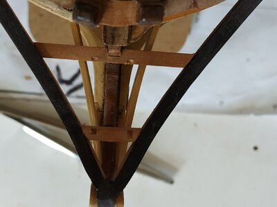
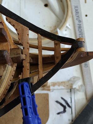
Head Carlings
These are a pair of fore-aft members used for the support of the Head Gratings.
They are let into the Head Beam and Crosspiece.
They are 1.6mm (from above) and 2.12mm deep.
They follow the curve of the Main Rail BUT from the SHEER plan (not the expanded view)
They separated to allow the Gammoning to pass between them.
The mortices in the Head Beam and Crosspiece are milled off-model .
I now realised that the Head Beam should be set further aft- the upright of the Standard is too wide and therefore sanded back.
The Carlings will be remade, longer, to fit the new position, when211022.jpg21a1022.jpg21b1022.jpg the Head Beam and Crosspiece are permanently fixed in position.
 
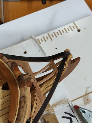
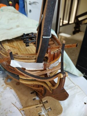
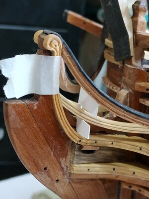
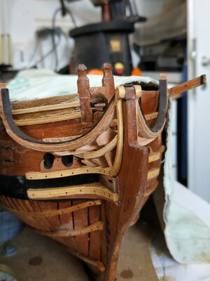
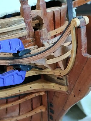
Lower Rail of the Head
Rests aft on the inner “arm” of the Hawse Bolster, and fore , the rising Hair Bracket.
The width (from above) is 1.9mm aft narrowing to 1.5mm fore.
Depth, 3mm to 2.4.
The molding starts a few mm before the aft end.
The points of contact with the Hull Requires shaping for the acute, curved angle.
*This rail as pictured is too high on the Hair Bracket, but in any case will be removed and replaced a number of times to allow the further building of the Head.

23a1022.jpg

23b1022.jpg

23c1022.jpg
 
Preparation for the Head Gratings
  • A series of ledges which form the surface of the head.
1.6mm wide, the section shape changes with their position.

The Batten.
Runs round the Bow, the upper surface level with the Head Beam and Knees.
They are 2.1mm deep and 1.6mm wide ( as I did not plank the port hull, this thickness is added to the portside width).
The position of the forward sections of the Waist, Sheer and Drift Rails need slightly altering and are removed.
(The patterns in TFFM show starboard different to port- to allow the optional fitting of an aft pair of seats of ease. I will not fit these.)
The Battens, Beam and Knees are removed so the mortises for the Ledges can be milled. (Ledges 1.6mm wide). These form a “fan”shape, and off model their position and angle can be matched.
The Battens are now fixed, Beam,Cross Piece, Carlings are temporarily removed.

241022.jpg

24a1022.jpg

24b1022.jpg

24c1022.jpg
 
Hello Stugio

I've been following your build report since the beginning. I am thrilled. What a fantastic overall impression. Since my upcoming project will be the Fly or Atalanta, I am batürlich glued to your build report and your work. Congratulations on the state worked out so far . That spurs me on very much. Thanks for showing it. Yesterday for my birthday I received more books to go with it. I will continue to follow your Bauberich with great enthusiasm.
Greetings Karlheinz
 
Hallo Stugio

Ich verfolge deinen Baubericht von Anfang an. Ich bin begeistert. Was für ein fantastischer Gesamteindruck. Da mein kommendes Projekt die Fly oder Atalanta sein wird, bin ich batürlich auf deinen Baubericht und deine Arbeit gespannt. Herzlichen Glückwunsch zum bisherigen Stand. Das spornt mich sehr an. Danke fürs Zeigen. Gestern zu meinem Geburtstag habe ich weitere Bücher dazu bekommen. Ich werde Ihren Bauberich weiterhin mit großer Begeisterung verfolgen.
Gruß Karlheinz
Charlie happy belated birthday, did you buy the Sea Watch Books? I hope you do a build diary.
 
Thank you. I now have ALL the books from Seawatch. Next spring I am no longer in the official working world...gggggg..... then I will devote myself fully to my ( our ) hobby / passion. I would like to share a build report about it with you and possibly write a book about it for me ( My Fly / Atalanta and I ....or something like that..) that would be my plan for my retired life . Thanks for your interest
 
Hello Stugio

I've been following your build report since the beginning. I am thrilled. What a fantastic overall impression. Since my upcoming project will be the Fly or Atalanta, I am batürlich glued to your build report and your work. Congratulations on the state worked out so far . That spurs me on very much. Thanks for showing it. Yesterday for my birthday I received more books to go with it. I will continue to follow your Bauberich with great enthusiasm.
Greetings Karlheinz
A very Happy Birthday. If I can do it, anyone can. As someone once said," I stand on the shoulders of giants".
I assume you have seen Dan Vadas's blog, the videos of Kevin Kenny.
I would invest in the 3D rendering of Greg Herbert.
The secret, as is everything in life, is patience.
Don't be shy to ask advice - learn by the mistakes of OTHERS my favourite teacher once told me.
 
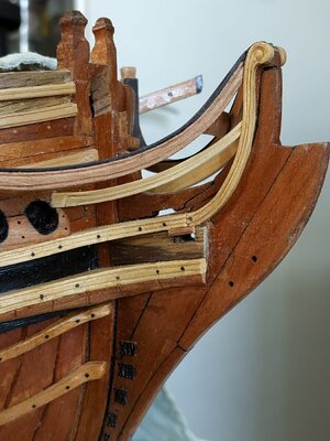
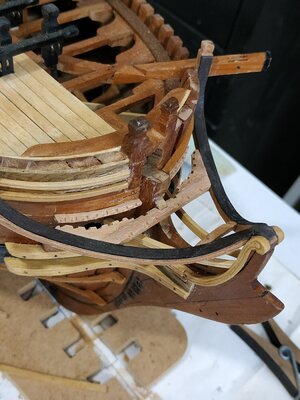
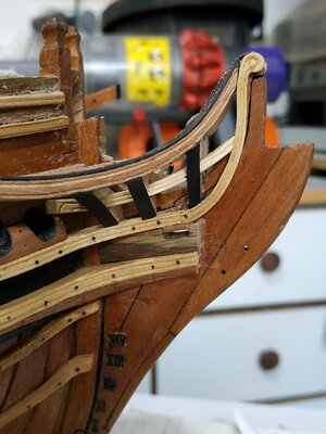
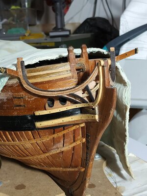
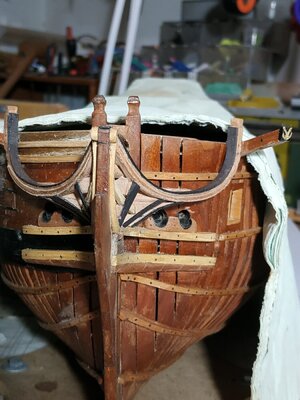
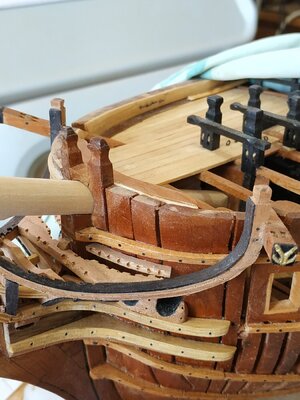
The Head Timbers

This is probably the most difficult and complex part of the build so far.

No wonder kits either omit or provide the whole as a preformed piece.
3D was helpful in how it should look-but not how to get there.
Dan Vardas , usually incredibly helpful, omits much of the process and mentions a problem with a camera. I suspect he threw it out of a sense of frustration.
Reliable TFFM was detailed - I just couldn’t understand most of it. (post-covid brain)

First decide the model has 3 or 4 Head Timbers- my plans do not show #1 - the aftermost. (thankfully).
#2 is below the Head Beam.
#4 is above the fore edge of the Trail Board.
#3 is between #2 and 4.
Their width varied- #2 -2.65mm, #3 2.4mm. #4-1.9mm
.
Anyway, the drafting advice was beyond me at my best.
It suggested as an alternative a CARD method. which I adapted.
Firstly remove the Carlings,Beam, and Crosspiece- I decided to leave the Main Rail in position, however.
Starting with #4
A piece of card is cut to the height between the upper cheek and main rail, and depth from the outer edge of the main rail to the Knee of the Head, at position of the aft (larger in this case) surface.
The Lower Rail is still in place, and its position marked on the card. A slot is cut at this level.
It was seen that my Lower Rail was too high on the Hair Bracket and was adjusted to sit lower,
The new position and slot adjusted to the card.
This is repeated for Timbers #3 and #2.
The Lower Rail is removed and each card is held in place so that the depth of the slot can be adjusted so the Lower rail can fit into its position.
This is repeated for the other side of the head.
A bridging piece is needed so as to include the width of the Extension piece of the Head for #4 and #3 (#2 sits either side and therefore aren’t joined).
The aforementioned difficulties are now apparent. The various and varying angles particularly with the Main Rail need addressing.
TFFM gives a way of marking the various angles with additional slips of card, but this didn;t work for me.
I went straight to a blank, roughly shaped to the card, and then by trial and error fitted into position. Then fashion the slot for the Lower Rail.
Note that, because of the acute curve of the Extension and Main Rail, slight change of position has a huge effect on the fit. Temporary gluing in place and releasing with alcohol is required (Unlike TFFM, I found photo glue not suitable)
Note also to shape upper surfaces to allow fitting of the Beam and Cross Beam.
The Outer surface (with its angle following the Main Rail ) can now be roughed out, It was found that the slot allowing the Lower Tail, requires “closing” and some additional wood was added.
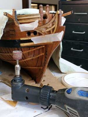
A final shaping of this surface requires some care, with protecting the Rails. VERY careful use of the sanding drum and the same drum, handheld, did the job.
This surface is covered by a Covering Board, 0.53 mm in thickness.
It is supposed to be paneled, but I made the whole from my black hornbeam wood.
To enable this to be fitted, the outer surface of the Timbers are cut back by 0.53mm, so that this Board is flush with the outer edge of the Main Rail above and the Upper Cheek below.
PHEW !!!!

261022.jpg271022.jpg26a1022.jpg26b1022.jpg26c1022.jpg11122.jpg21122.jpg2a1122.jpg31122.jpg3a1120.jpg3b1122.jpg3d1122.jpg3e1122.jpg
 
The Head Timbers

This is probably the most difficult and complex part of the build so far.

No wonder kits either omit or provide the whole as a preformed piece.
3D was helpful in how it should look-but not how to get there.
Dan Vardas , usually incredibly helpful, omits much of the process and mentions a problem with a camera. I suspect he threw it out of a sense of frustration.
Reliable TFFM was detailed - I just couldn’t understand most of it. (post-covid brain)

First decide the model has 3 or 4 Head Timbers- my plans do not show #1 - the aftermost. (thankfully).
#2 is below the Head Beam.
#4 is above the fore edge of the Trail Board.
#3 is between #2 and 4.
Their width varied- #2 -2.65mm, #3 2.4mm. #4-1.9mm
.
Anyway, the drafting advice was beyond me at my best.
It suggested as an alternative a CARD method. which I adapted.
Firstly remove the Carlings,Beam, and Crosspiece- I decided to leave the Main Rail in position, however.
Starting with #4
A piece of card is cut to the height between the upper cheek and main rail, and depth from the outer edge of the main rail to the Knee of the Head, at position of the aft (larger in this case) surface.
The Lower Rail is still in place, and its position marked on the card. A slot is cut at this level.
It was seen that my Lower Rail was too high on the Hair Bracket and was adjusted to sit lower,
The new position and slot adjusted to the card.
This is repeated for Timbers #3 and #2.
The Lower Rail is removed and each card is held in place so that the depth of the slot can be adjusted so the Lower rail can fit into its position.
This is repeated for the other side of the head.
A bridging piece is needed so as to include the width of the Extension piece of the Head for #4 and #3 (#2 sits either side and therefore aren’t joined).
The aforementioned difficulties are now apparent. The various and varying angles particularly with the Main Rail need addressing.
TFFM gives a way of marking the various angles with additional slips of card, but this didn;t work for me.
I went straight to a blank, roughly shaped to the card, and then by trial and error fitted into position. Then fashion the slot for the Lower Rail.
Note that, because of the acute curve of the Extension and Main Rail, slight change of position has a huge effect on the fit. Temporary gluing in place and releasing with alcohol is required (Unlike TFFM, I found photo glue not suitable)
Note also to shape upper surfaces to allow fitting of the Beam and Cross Beam.
The Outer surface (with its angle following the Main Rail ) can now be roughed out, It was found that the slot allowing the Lower Tail, requires “closing” and some additional wood was added.
A final shaping of this surface requires some care, with protecting the Rails. VERY careful use of the sanding drum and the same drum, handheld, did the job.
This surface is covered by a Covering Board, 0.53 mm in thickness.
It is supposed to be paneled, but I made the whole from my black hornbeam wood.
To enable this to be fitted, the outer surface of the Timbers are cut back by 0.53mm, so that this Board is flush with the outer edge of the Main Rail above and the Upper Cheek below.
PHEW !!!!

View attachment 338220View attachment 338221View attachment 338222View attachment 338223View attachment 338224View attachment 338225View attachment 338226View attachment 338227View attachment 338228View attachment 338229View attachment 338230View attachment 338231View attachment 338232
excellent work, my Dear friend :) Thumbsup
 
Ohhh, that's what they look like. I may have to go back and re-do the head on the Discovery1789. I had the same problems as you did, and I was really disappointed when Dan's camera broke. Even the make-up pictures he did didn't show the head timbers well and I wasn't sure what I was building. You've explained them well. Thank you.

As a little add on, George Vancouver's journal mentions them having ongoing difficulties with their head. The weather destroyed it two or three times before they got to Hawaii. So maybe we aren't the only ones that have problems designing and building them.
 
Decision Time
To rig or not to rig- that is the question.
Or short symbolic masts, or none.
This was supposed to be an “undressed” model-although much remains hidden by the ribs and decks.
I intend to make a swan again, but with full planking, minimum internals and fully rigged.
Why the opening question? Well, how do I deal with the Bowsprit?
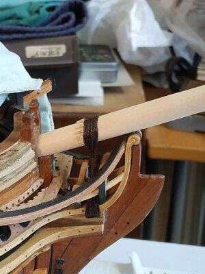
Decided short, but enough to show the Gammoning, which is very much part of the Head.

Bowsprit.
Make it long enough to include the Saddle ,about 15cms
A max. Diameter 10.9 mm- narrow forward slightly by 2mm, but aft to 9.35mm before ending in a square 6.5, narrowing to 4.5mm (to fit in the Bowsprit Step).
I used lathe and sandpaper strips.
Ensure that it fits through the Stem Head and Cross Chock.
According to the plans, the Bowsprit rests at 20 deg to the horizontal.
By some miracle, the square “heel” fits into the Bowsprit Step.

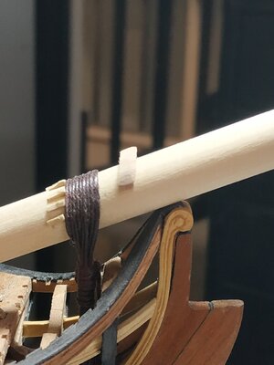
Gammoning Cleats.
A line of oblong short strips, 3.7 long and 1.06 sq -slightly wedge shape when viewed from the side.
Varied in number between 5 -9 ( I made 7)
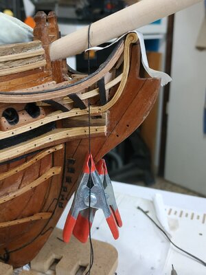
They are fixed to the Bowsprit so that the fore edges align vertically above the fore edge of the Gammoning Slot. I used a weighted string to mark this line.41122.jpg61122.jpg
The outer pair at position 3 and 9 of the clock, the rest evenly spread.
 
The Gammoning.
(note need to read forward to ch.15 TFFM or other reference book)
A tired line circumference 2.4 -diameter 0.8mm
TFFM suggests starting with 30cms but I found this much too short- I used 100cms.
Starting with a (pretend) eye splice, pass the line around the Bowsprit and through the eye so that it hangs to the left. (Elderly gentlemen may recall another significance for this.)
Moving through the Slot up against the fore edge, returning over the Bowsprit, against the cleats,the turns are repeated until an EVEN number of turns fills the slit.(My case=8)
The descending line is now taken between the upright turns, alternating port and starboard, interspersed with half hitches, for a similar number of turns.The loose end is half hitched through the last 2 turns.
6a1122.jpg
 
If you plan on building another Swan and rigging it, why not rig this one? I'm trying to follow your reasoning as I'm going to have the same decision soon. Well, not too soon :)
 
The Saddle for Running Rigging
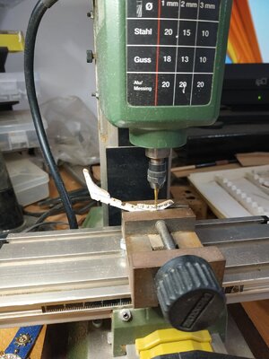
A (less than) semicircular wooden collar sitting slightly forward of the Gammoning
Although 3.18mm width and height, a block needs to be bigger because the lower and upper surfaces are beveled to parallel the Bowsprit.
A number of holes pass through the collar - variously 4 to 7.
I made 7- diam. 0.8mm
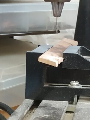
To angle them correctly, I held the (marked) block in the vice and used a drill press.
As suggested by TFFM, bevel the underside and after fixing to the Bowsprit, the upper surface is more easily beveled, as required.

IMG_20221106_101924.jpg

IMG_20221107_141152.jpg
 
If you plan on building another Swan and rigging it, why not rig this one? I'm trying to follow your reasoning as I'm going to have the same decision soon. Well, not too soon :)
I could, but problems such as half decks and the few hull planks and wales are on one side only.
I want to build a "complete" planked hull and then won't have to compromise and adjust the masts and rigging. Also I have 5 other builds that await
 
Cathead Supporter
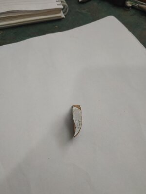
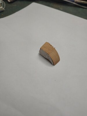
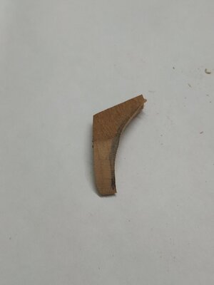
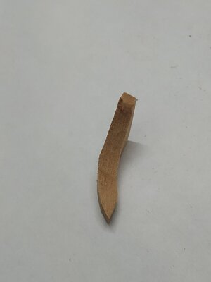
A knee supporting the Cathead.
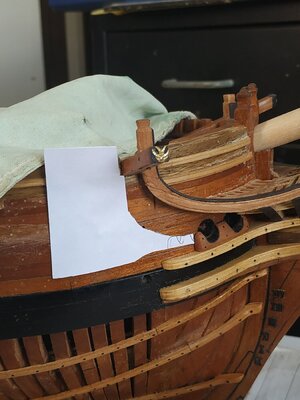
TFFM recommends cutting out a paper pattern to follow the AFT curve and stick it (photo glue) in position on the Bow. This is an excellent idea and simplified the repositioning of the piece accurately when frequently offering up and modifying the piece with its complex curves.
Although the final width is only 2.9mm, a larger blank is required.
I started with 6.5x16x25mm
I thought I would detail how I deal with various curves - possibly like others, but it might help a few.
The order these curves are made may vary, but again following TFFM this was made easy.
Start with the upper angle of the Steeve where it lies under the Cathead- in my case 110 deg.
The aft edge of the Supporter is initially vertical before curving forward. I stuck a cutout pattern (reversed) and roughed out the shape.
The Inner surface is then fayed to the hull.
The forward surface can now be marked to follow the aft, and the piece shaped and thinned with files to slightly more than the required 2.9mm
The concave curve of the outerface can be shaped, keeping said face at right angles to the aft face.
A scarf joint is made at the lower end where the Eking Rail will be joined.
91122.jpg9a1122.jpg9c1122.jpg9d1122.jpg9e1122.jpg9f1122.jpg9i1122.jpg9j1122.jpg
 
Back
Top