Swan Class – ¼” Scale - Stuglo [COMPLETED BUILD]

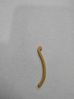
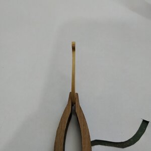
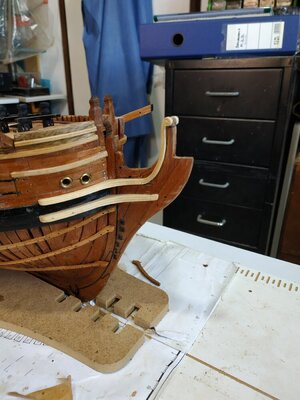
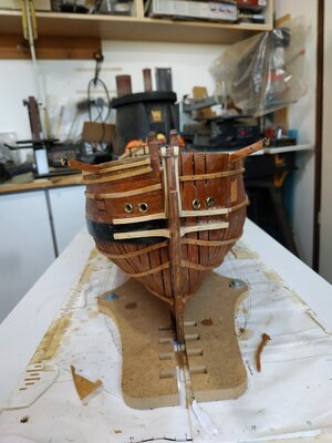
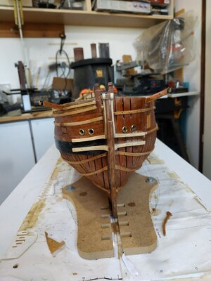
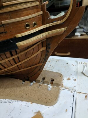
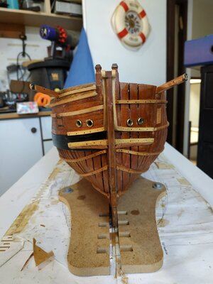
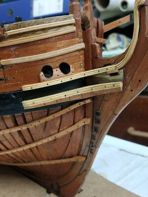
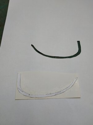
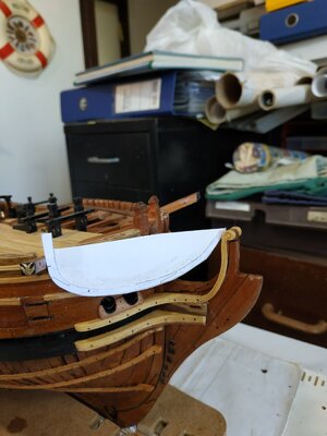
Quarter Deck Breastwork, revisited.
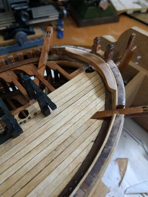
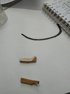
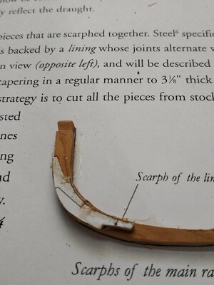
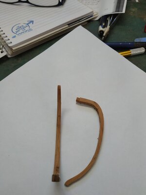
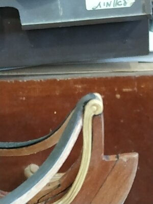
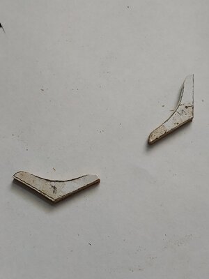
Well that attempt was not exactly satisfactory, so try again.
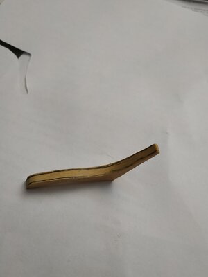
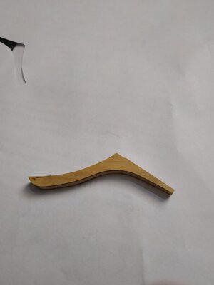
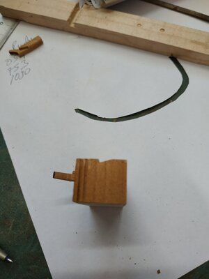
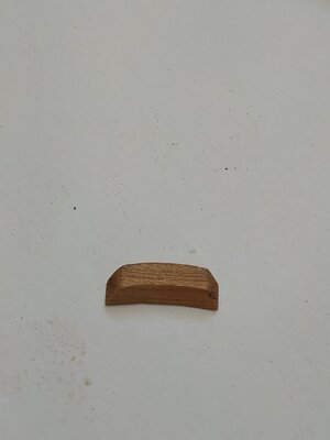
Start with the block for the whole length, turned using a shaped cutter fixed in the lathe.
It Works !!
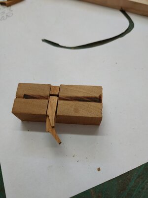
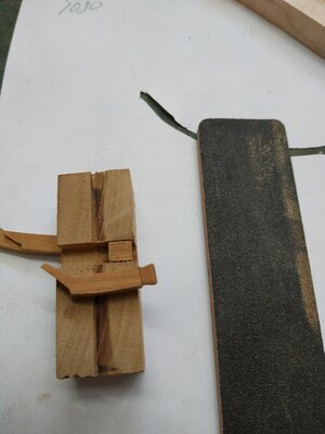
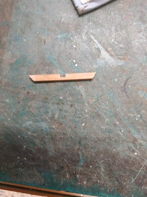
I have found that cutting slots this thin, even with a drill press, doesn't give me a correctly-positioned hole/slit on either side of the piece, so I cut a wider slot, 1.6mm and put a 0.75 mm “wall” in the center to separate the sheaves.
I think this looks better than the previous attempt.
Don’t forget to pin as well as glue , to the deck- because I did !!View attachment 330121View attachment 330122View attachment 330123View attachment 330124
wonderful work my dear friend, and happy new year :) Okay
 
Fixed Gangway
A short platform forward of the Quarter Deck.
Supported by a frame, the top of which is level with the Planksheer (not yet fitted), and athwartship ends tenoned onto the string at the waist.
Therefore the Gangway surface is proud of this. It is angled to match the deck camber.
The perimeter beams are 2.12 mm sq-athwartship 1.12 x1.59 mm thick.
The foremost frame sits between 2 knees..
The Gangplanks are 4.77mm wide and 1.33mm thick, surrounded by a frame 3.25mm wide, slightly larger than the frame it sits on.

Planksheer.
1.6mm thick, overhanging the outer planking by 1.6mm, and flush with the inner hull planking.
I found “molding” the outer edge impossible, and so only chamfered it.

Gangplanks.
A pair, each 4.77mm wide, sitting on knees previously fitted, outer edge against the planksheer at an angle to match the deck.
Extends beneath the foredeck to the forepart of Gangway frame.
The 2 planks are fastened together with bolts 25mm apart.

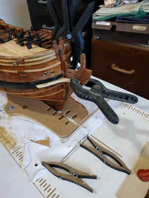
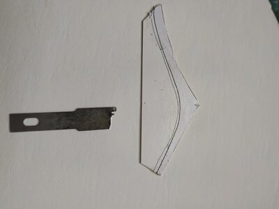
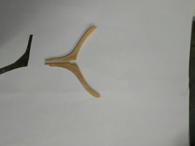
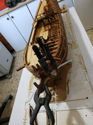
Breasthook over the Bowsprit
Fits just below the Drift Rail, 4.1mm thick- length along arms 70mm
Sanded so the upper surface is flush with the toptimbers.
The central part, underside needs hollowing out to allow fitting of the Bowsprit. This I did after gluing in place.
IMG_20220928_080003.jpgIMG_20220928_080023.jpg
 
Structures of the Head.
I always considered these the most difficult part of a build -even with a kit.
TFFM seems to lay out instructions and an order that hopefully will minimize the stress and mistakes.
Lower Cheek
Shaped like a knee.
Foreward arm, with slight upward curve- the arm against the hull almost straight and follows the lower edge of the center wale, to which it is attached.
Sided 3.45mm-slightly tapering forward
Depth (looking from above) 4.24 mm tapering to 1.72m
(As no planks on port side, thicker part to compensate)
I used the horizontal pattern then the side view pattern for cutting to shape and sanded to fit.
Molding with a shaped chisel blade.
The foreward extension is too long-will be altered later when the Figurehead is fitted.
29a22.jpg29b22.jpg29c922.jpg
 
Upper Cheek
Same basic shape as lower cheek but extentends upward and forward in an extra piece, called a Hair Bracket, that is connected by a scarf joint.
The parallel part is separated from the Lower Cheek by a gap of 6.9mm
It is sided at 3.18, narrowing to 2.65 forward, with width 4.0 to 1.6mm before widening at the top to 2.5mm
The TFFM suggests making in the 2 parts, sticking them together, and then attaching them.
I found that I couldn’t keep the aft part still without gluing it in place first.
(Because the part is narrower, a new mold-maker was required)
I made the Hair Bracket at more than double thickness, cut it in half with bandsaw, so that both halves would match.
The topmost part , has a scroll or other fancy molding, and matches form of the Extension Piece of the Knee of the Head

30922.jpg

30a922.jpg

30b922.jpg

41022.jpg

4a1022.jpg

4b922.jpg
 
Good luck Stu. I'm just heading out to make the seats of ease and the head will be done. I had the most trouble with the cathead knee. I just couldn't wrap my head around the shape. Once I figured it out it wasn't so bad but I bet I puzzled over it for 2-3 hours.
 
Wash Cant
Placed under the Lower Cheek to act as protection. I misunderstood the instructions and made it too thick. Reviewing the 3D rendering, I saw that it thins toward its61022.jpg91022.jpg101022.jpg10a1022.jpg aft end. I reshaped it while in situ with a chisel blade and sanding stick.
The spaced scores represent plank joints, as it is said not to have been made out of a solid piece of wood.

Trail Boards
Between Upper and Lower Cheeks. Variation among different ships as the aft extension.
Thickness 1.6mm.
It was carved, but I have simply used a variable-coloured grained wood.

The is a Chock above either side of the Gammoning Slot.
Its lower edge is rounded to facilitate the Gammoning.
My chock is too narrow as the slit should have been lower.

Bolster.
A chock to reduce wear on the cables.
Back shaped to fit hull. Thickness less than the lower Cheek it sits on.
The groove extends half way up the Hawse holes
(I removed the brass portholes and blackened the area to represent lead lining)
The Bolster is rounded front and sides, attached with 3 pairs of bolts
 
The Main Rail
TFFM says not to worry-easier than it looks Ha! Ha!
Good explanation about the plans distorting, but I didn’t understand the solution. So I just cut the pattern of the expanded example, backed onto card and it seemed to fit.
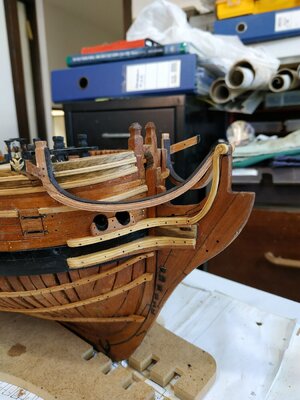
The Rail consists of 3 parts- Main (outer), Lining(inner) and Planksheer(above).
The first two have scarfe joints that are staggered.
Stock for the outer rail is 2.9mm sq.- lining 2.9x1.33 mm.

In order to make the Timberhead, I made the aftermost part of each rail first.
These were placed in a jig so the shaping was consistent.
(The Jig was milled and filled and the base of the groove is colored to show when to limit the shaping of the piece-using a sanding stick)
121022.jpg12a1022.jpg12b1022.jpg12c1022.jpg12d1022.jpg12e1022.jpg
 
Main Rail cont.
Laying down the outer rail first on the pattern, then completing the lining.
The combined piece is left slightly over long until a groove, triangular in section, is scored into the aft face to allow fitting against the Cathead.
The Main Rail also narrows moving forward, BUT ONLY IN THE OUTER RAIL.
I.e. the Lining thickness remains constant.
1.33+2.9 narrows to 1.33+1.5mm.

131022.jpg

13a1022.jpg
 
Molding of the Main Rail
Below the level of the Cathead are 2 “step downs”
The 1st thins the Rail by 0.53mm- upper and lower limiting lines supposed to be “S” shaped-easier said than done.
The next step meets the depth of the groove of the molding.
The outer face of the Rail is bevelled151022.jpg15a1022.jpg181022.jpg18a1022.jpg to half thickness at lower edge to simplify the scrapping.
I had no readymade scrappers to match the patterns suggested- in any case I made a fundamental error in using cherry instead of boxwood-the cherry doesn’t take to scrapping and the end result was not satisfactory.
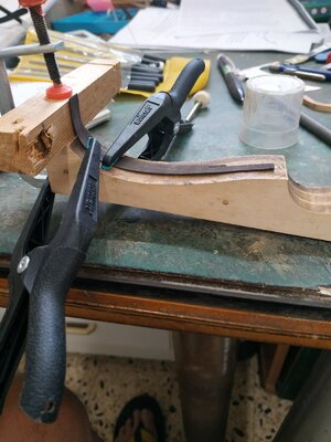
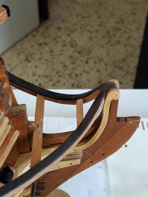
TFFM suggests the possibility of extra run of molding, but I wanted a contrast and used a separate planksheer. Even though this is only 0.53mm, the blackhorn is brittle, so I used hot water and a bending jig.
A thin overlap outwards and the inner side is trimmed to match the inner edge of the lining rail.

Scoring for the Cathead, a triangular section groove so that the top of the Timberhead is 9.5mm above the Toptimber Line.(Some of the hull molding e.g. sheer, needs cutting away.
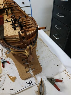
The assembly can be fitted so the whole is in a vertical plane, and the Timberhead is also vertical.Also check for symmetry of the curves when eyeballing from the stem.( Not so easy as the wales and moldings are on one side only on my model.)
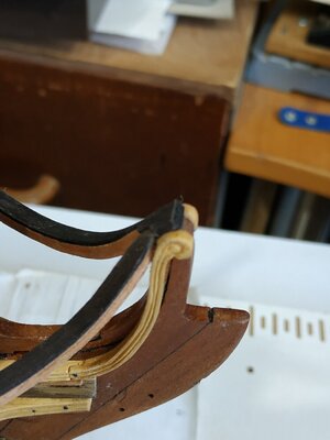
The foremost end is shaped to fit behind the Hair Bracket.
When all seems set, I’m left with a small gap between these ends.
There is a bolster to be fitted later, to finish this off. I fitted it now so I won’t see the error which otherwise would annoy me and force me to scrap the lot and start again !.

18b1022.jpg
 
Molding of the Main Rail
Below the level of the Cathead are 2 “step downs”
The 1st thins the Rail by 0.53mm- upper and lower limiting lines supposed to be “S” shaped-easier said than done.
The next step meets the depth of the groove of the molding.
The outer face of the Rail is bevelledView attachment 335371View attachment 335372View attachment 335373View attachment 335374 to half thickness at lower edge to simplify the scrapping.
I had no readymade scrappers to match the patterns suggested- in any case I made a fundamental error in using cherry instead of boxwood-the cherry doesn’t take to scrapping and the end result was not satisfactory.
TFFM suggests the possibility of extra run of molding, but I wanted a contrast and used a separate planksheer. Even though this is only 0.53mm, the blackhorn is brittle, so I used hot water and a bending jig.
A thin overlap outwards and the inner side is trimmed to match the inner edge of the lining rail.

Scoring for the Cathead, a triangular section groove so that the top of the Timberhead is 9.5mm above the Toptimber Line.(Some of the hull molding e.g. sheer, needs cutting away.
The assembly can be fitted so the whole is in a vertical plane, and the Timberhead is also vertical.Also check for symmetry of the curves when eyeballing from the stem.( Not so easy as the wales and moldings are on one side only on my model.)
The foremost end is shaped to fit behind the Hair Bracket.
When all seems set, I’m left with a small gap between these ends.
There is a bolster to be fitted later, to finish this off. I fitted it now so I won’t see the error which otherwise would annoy me and force me to scrap the lot and start again !.

View attachment 335375
wonderful work my dear friend ThumbsupThumbsupThumbsup
 
Head Beam
Runs athwartship and ties the Head Rails together.
Sided 3.98mm deep 2.9mm. In section parallelogram.
Rounded up by 0.8mm.
Half-jointed to the Standard (of stem), which is curved - the mortice adjusted for this.
(of course, after making this perfectly, I realised it was upside down instead of upper surface convex. CHECK EVERYTHING TWICE).
Do not fix it permanently yet.

Knees
Reinforces corner of Beam and Main Rail
Sided 2.12mm. Arms 14.3
Do not fix it permanently yet.201022.jpg211022.jpg
 
Cross Piece of the Head
(A really fiddly little bit to make)
Positioned with 4th Head Timber above the fore edge of the Trail Board, between the Main Rails.
It performs a similar function to the Head Beam.
It is 1.6mm wide, with a rhomboidal section.
Similar rounding up 0.8mm, the upper and lower surfaces beveled to follow the curve of the Main Rail.
I started with a block 6.6 deep to allow for the various curves. The ends are angled acutely to fit between the Main Rail.
Again not permanently fixed.20a1022.jpg20b1022.jpg20c1022.jpg
 
Last edited:
Back
Top