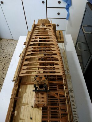
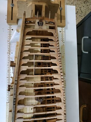
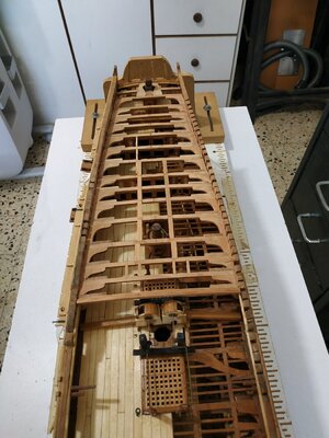
Swan Class – ¼” Scale - Stuglo [COMPLETED BUILD]

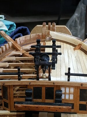
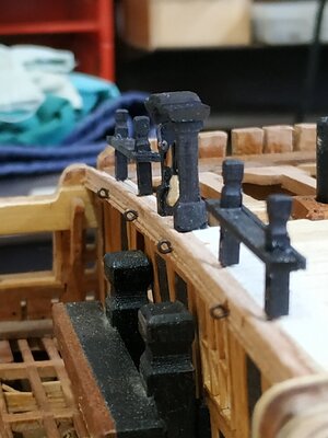
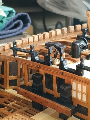
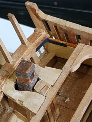
The Cowel
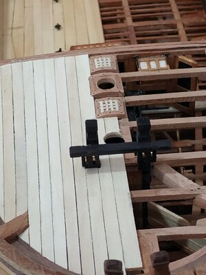
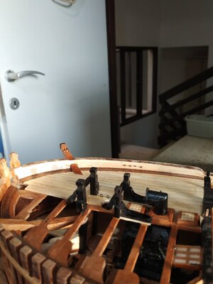
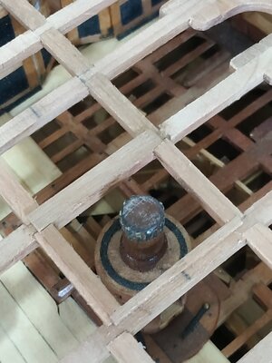
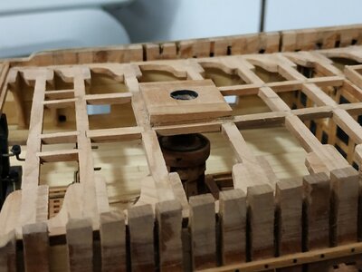
Sits on the upper chimney of the Stove, and passes through the foredeck via a hole in a metal plate. The Cowel Base.
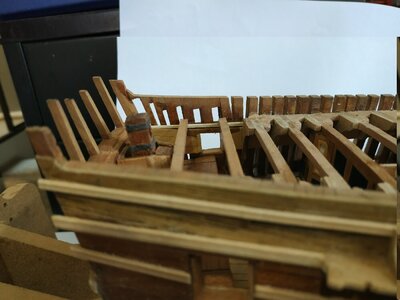
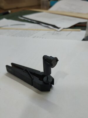
I used a wooden dowel, cut at an angle slightly more than 45deg, instead of fabricating from metal.
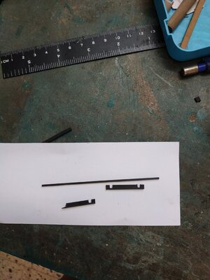
The opening faces forward, but the air intake is regulated by a Baffle. This is a thin disk, slightly larger than the aperture, which can be moved fore/aft. I made this also from a thin slice of dowel. The slides are made from cutdown dressmaker’s pins, the tube from insulation for thin electric wire, and the handle from copper wire. The ensemble painted black
20a722.jpg
 
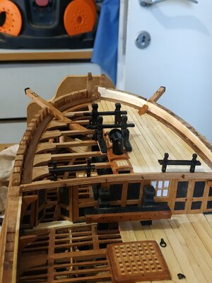
Planking the Forecastle.
The planks are 1.33mm thick.
The Centreplank is of similar thickness, but a bit wider.
As all the planks are less than 22ft no butt joints are necessary.
The planks taper, approx 4mm foreward, to 4.77mm aft. This gives a curved effect.
The 7th plank passes over the Cathead, whose upper surface is notched to allow this plank to lie flush with its neighbours.
The tips of the next 3 planks are “barbed” otherwise the end width would be too narrow.
I’ve penciled the edges and left gaps between the planks to represent caulking,but I do not plan to nail as the effect, to me at least, often seems exaggerated. ( I understand that they probably couldn’t be seen-hypocrite that I am, I like them on the hull and elsewhere,as decorative features.)

20722.jpg
 
Sheaves and Brass
The wooden sheaves look terrible.
I ordered some brass rods recently but have only a simple lathe (built from 6in1 classic Unimat)
No suitable cutting tools, although I adapted some small screwdrivers for woodwork.
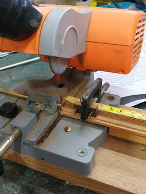
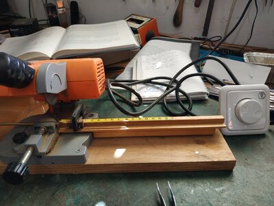
I have an old mitre cutoff saw. As scratch building doesn’t lend itself to mass reproduction, I’vr not used it for a couple of years.
No special blade, I can cut through the brass.
The brass gets pretty hot and sometimes the saw sticks.
I decided to slow it down and connected a light “dimmer” switch. It is much improve and gives me down to 0.5 mm slices
(The central holding screw is rusted in -WD40 doesn't work. Please advise as I would like to change the blade to carbide-tipped or a cutting disk)
Also, not able to make the required grooves.
I welcome suggestions to adapt by toy lathe and the tools I will need to slice groove shape etc

21722.jpg

21a722.jpg
 
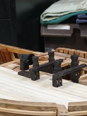
Fore Jeer Bitt Pins and Standard.
Unlike others, these are bolted down over the deck planking.
In form, similar to Fore Topsail Bitt.
The Pins are 3.71mm sq. and the standards , if I understand TFFM correctly, are made of one piece with them.
I anticipated difficulties in making the various moticses, sheave slits shaped tops etc, so I made them separately, did the necessary milling and drilling, then stuck them together.
The crosspiece is again 3.45x2.39x36mm, the lower surface 9mm above the planking.
The sleave slit extends through the Standard, but this can now be made in the drill bench press.
A set of brass disks are fitted as sheaves.
The Pins sit on beam#4 and extend aft so the Standard near the Cowl Coaming

21b722.jpg
 
Fore Jeer Bitt Pins ו-Standard.
שלא כמו אחרים, אלה מוברגים מעל הקרשים של הסיפון.
בצורה, בדומה ל-Fore Topsail Bitt.
הפינים הם בגודל 3.71 מ"מ והסטנדרטים, אם אני מבין נכון את TFFM, עשויים איתם מקשה אחת.
ציפיתי לקשיים בהכנת המוטיקות השונות, חרכי גזירה בצורת חורים וכו', אז הכנתי אותם בנפרד, עשיתי את הכרסום והקידוח הדרושים, ואז הצמדתי אותם זה לזה.
החלק הצולב הוא שוב 3.45x2.39x36 מ"מ, המשטח התחתון 9 מ"מ מעל הקרשים.
חריץ השרוול משתרע דרך הסטנדרט, אך כעת ניתן לעשות זאת במכבש הספסל המקדח.
סט של דיסקים פליז מצוידים כאלומות.
הפינים יושבים על קורה מס' 4 ומתרחבים מאחור, כך שהתקן ליד ה-Cowl Coaming

View attachment 319542
wonderful work my dear friend :) בסדר
 
Forecastle Bulwark Planking
Referring back to ch.4 - the inner planking expansion.(planks 26,27,28)
#26, short plank aft of Breast Beam
#27, the lower strake interrupted by the Catshead, continues to Bowsprit
#28, the upper strake widens over the Catshead, and encloses the upper part of the Bowsprit.
I had difficulty making this in one piece. Cutting to size and accurately placing the expansion over the Catshead didn’t seem to work even with the plank heated to take the bend.
After 4 or 5 attempts, I took the cowards way out, and divided the plank above the Catshead.

A series of 4 eye bolts are countersunk on the #27. These are referred to as the Ironwork.
Countersinking, as suggested by TFFM, using a narrow flat screwdriver. The (shortened) eyebolt is fitted after drilling the usual hole in the center of the depression

IMG_20220728_185412.jpg
 
The Forecastle Breastwork.
This is the Railing at the aft end of the Forecastle, either side of a central Belfry.
Stanchions:
A pair either side, with sheaves.
2.25mm sq., 12.75mm tall. Shaped similarly to the tops of the Bitt Pins
The sheave, 0.46x2.12mm in a slit beneath the Rail.
Pegged (part brass pin) onto the Breast Beam, ensuring they are vertical.
Rails:
4.24X1.33mm enclosing the Stanchions. Again, as suggested by TFFM, made with notches and a finishing strip.An accurate square “hole” is difficult.
Cutting this notch with a knife,chisel or saw, caused breakages to the thin blank. The milling bit did a better job
The practicum calls for creating a molding around the edges. I found this impossible. Rather I chamfered these edges.
The Rails are fixed parallel to the deck.

The Belfry .
Consist of 2 Stanchions, a Canopy (roof) and Headstock,from which suspends a bell.
The Stanchions 4.77x2.25x16mm. With thickening at top and base.
The Canopy. I decided to make this as a shaped single piece, rather than 3 pieces.
Omega shaped, also edged with a stepped molding, which I again failed to create and so chamfered.
Headstock. 1.6mm wide, yoke shaped. Placed halfway up the Stanchions.
The “V”metal straps, using thick black paper. At its base is the brass Bell.
Max width and height about 4.5mm and bell-shaped.
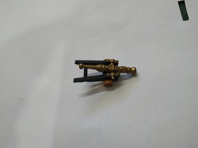
My efforts at brass turning are so far pathetic. Looking for something to adapt, I saw the end of a cannon left over from a kit. Cutting this and shaping with a sanding wand, seems ok.
Above the Headstock is a bell crank - a ready made eyebolt bent to shape.
The above was assembled and fitted, and only now I made the Spar Rack.
I think this was easier, rather than before the Belfry.
Spar Rack. Filling the gap between the inner Stanchions and the Belfry.
Width again 4.24mm, “U” shaped, the outer limb fits under the Rail, the other is this height + 1.33mm (thickness of the Rail). The outermost edge shaped to fit the neighbouring edge of Belfry Upright.
Again shaped by my Proxxon mill - a really useful machine.

2672022.jpg

27722.jpg

26a72022.jpg

28722.jpg

28a722.jpg

28b722.jpg
 
HELP WANTED !!

Thickness of Beams and Lodging Knees.

Both these sit on the deck clamps. How can they sit flush if they are different thicknesses. Lower and possibly upper deck beams are let down. I cheated with the forecastle and made thicker knees.

I can't see a different solution for the quarter deck, where the beam is 5.5 in and the knee only 4.5 in.

What am I missing?
 
I think the continuous clamp would be a lot stronger than, say, blocks on each frame or something. Also I don't think the beams necessarily match up with the frames either.
I suppose the knee could be down on the clamp and the planking and waterways would just bridge over the dip. I dunno. I'll look at a few examples in Steel to see if lodging knees are usually the same thickness as their associated beams.
 
According to Steel it doesn't look like the lodging knees are as thick as the beams on any sized ship, at least on the quarterdeck anyway. This is assuming that I'm reading Steel right. This means my whole ship is wrong cause I made them all the same thickness. I think I'll leave this one :) :)
 
Quarter Deck Beams.
These have already been made so as to enable fitting of upper deck bulkheads.
The Beams are 2.9mm deep.
I posted a question on how to reconcile this depth, without Letting Down if the Lodging knees are only 2.39mm, as these usually sit on the deck clamp. In order that the upper surface is flush with the Beam, this must mean that either the Beam is let down by 0.51mm, the Knee is thickened to match the beam,2.9mm or the knee doesn’t sit on the clamp.
I went with the thickened Lodging Knee.
The “arms” of the L.K. are 19.1m
The Hanging Knee is 2.65mm thick, arm 17.49mm and leg over the spirketting.
I REMEMBERED to mill mortises for Carlings before fitting Beams.
The Carlings are all 2.65mm deep but varying widths.
For the: Scuttle, 2.39mm width
Ladder Way 4.5 mm
Between Beams #5 to #9 the Carlings are 4.1mm wide. The form a line which tapers, so that the distance between the carlings at Beam #5, are 24.5mm and at #9 =22.5mm.
I had some difficulty fitting the Lodging Knees after the Hanging Knee and its aft partner were fitted, because the “tongue” of the L.K. would break off if fitted to closely into the notch of the H.K.
In the end, dry fitting the assembly and then gluing the knees before finally fixing the Beam.
The fore/aft bulkhead can be fitted after #8 Beam in place.
The Mizzen mast partner is fitted between #9and#10, and the beams are scored to 0.53mm for the mortise.
Beam #15 scored for the Rudderhead framing mortise and fitting to the angle of the Rudderhead itself.
Only when the Beams and Knees were already fixed in place, I noticed that aft of Beam #10, the Beams were not aligned with the Transom on the Port side, the deck didn’t angle upwards sufficiently.
Ungluing everything, I saw the cause was the height of the upper port framing and the neighbouring spirketting.
To correct this, I added a long wedge of inner planking, from 0 to 2mm at the Transom.
The Beams and Knees refixed (some being remade) and this problem solved
There is no room for a Hanging Knee at #14 Beam, so it was omitted. 9822.jpg10822.jpg
 
Rudderhead Framing.
Three pieces of 2.65mm, 2 sides and 1 joining piece aft of the Rudder.
Rabbeted joints, they sit flush with beam#15 and the Transom, aft. This latter also needs scoring.
The opening is fan-shaped to allow rotation of the Rudder.
The height of the Rudderhead Trunk needs adjusting to allow the frame to sit on it.
TFFM suggests an half-beam from either side of the frame to the deck clamp. This requires scoring the Frame.
An Iron Knee is fixed between the Transom and inner hull planking.
I made this with thick, black card.9a82.jpg10b822.jpg
 
The Quarter Deck Carlings.
These are 2.65mm deep and varying widths. As before, mortised onto the Beams.
Foreward, they form the base for a pair of scuttles. They are 2.6mm wide.
The Ladderway carlings are 4.5mm wide
The carlings for the Capstan Partner are 4mm wide.They are parallel.
Between Beams #5 and #8. The carlings are also 4mm , but the gap narrows from 24.5 to 22.5mm.

12822.jpg
 
Mizzen Mast Partner
Only 1.06mm thick, can be made in 1 piece (see 3D rendition)
The hole for the mast is 6.89mm, and towards aft end of the piece.
The fore and aft sides are scored down so they sit flush with the Beams.
The 1st piece broke, so on second attempt, made smaller hole, glued piece in place, and after planking, the piece being reinforced, will enlarge the hole

The Quarter Deck Capstan Partner.
Similar construction to the upper deck CP-3 pieces (2.65mm thick) rabbeted together.
They don’t sit directly on the beams, but onto Bearer pieces. I made these 2mm, but shaped to fit the curve of the beam,so the bottom edge of the CP sits at deck level. Thus their upper surface is horizontal, onto which the CP sits.( I also put them on the carlings : I didn’t really understand the adapted Carling instruction until after I finished-it comes to the same anyway)
The aft bearer is the width of the beam (4.24mm) but the fore bearer (on beam #4) is only 1.59mm wide.
The hole is centered above the Capstan Barrel previously fitted. It is lined by an iron hoop, 0.4mm (thickness of my black paper), thus I made the hole 9mm diam.
The Partner must sit horizontal to enable the Capstan to turn on a vertical axis.
The lower surface is milled and sanded to a wedge-shape (looking from side), the aft edge reduced to about 2mm.
( Holes are also prepared for the ladder stanchions. Why? The ladderway coamings are similar fore and aft. Ok for fore, why not aft. Also looks funny to my eye.)14822.jpg14a822.jpg
 
Back
Top