Swan Class – ¼” Scale - Stuglo [COMPLETED BUILD]

Start with something easy-smooth aft ends of sternpost.Next TFFM suggests read section on making the rabbit. Like many things, I find it difficult to grasp until I actually do it. So another easy job, tapering the aft section of keel to thickness 5.3mm. Alternate sanding on sanding board withe increased finger pressure on aft part which needs thinning the most. As stated, this taper starts at station 14 (which we can now find quite easily)Double check height of deadwood against innerpost, the extra previously left can be removed using the lowest filling transom as a guide.
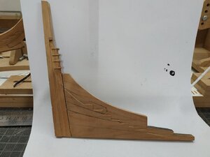
I firstly made the vertical rabbit on the sternpost. This is where the 3D rendering becomes invaluable. It appears narrowest at the top I guessed by measuring the plans, that width is 1.6 mm. I set the depth at 0.8mm to match the seats of the transoms. Remembering the sternpost is narrowing at base, this was wedged (handle of one sided razor), and aligned so that a pass with the milling bit nicely set the aftmost extent of the rabbit.
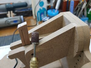
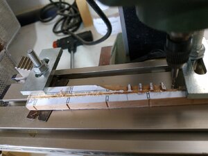
*****Its next suggested to cut and glue the Rising wood which acts as the upper limit of the keel rabbit. I Cut the roughly to get an idea of form, but decided NOT to fit the yet. Success with milling the first rabbit encouraged me to mill this on the keel without the encumberment of the Stern complex. Fixed metal clamps to back of millin base a guide and setting same bit as already used, set at upper edge of keel and depth again 0.8mm. Note points where rabbit starts to rise fore and aft, moved the piece along the base, keeping the bit still. A nice clean horizontal cut out appears. I've made rabbits with steel rulers, scalpels. files etc but never so cleanly or quickly. The depth and shape can be easily adapted later. The change of direction and form of the rabbit beyond the horizontal section, will be done in the conventional manner.
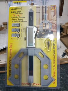
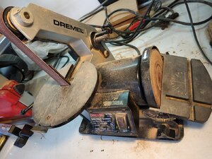
Last picture is my new toy.16a.jpg16c.jpg16d.jpg
 
stuglo, my Dear friend
The last thing that can be said about you is, stupidity! Cautious
From my personal acquaintance with you, the opposite is true:D
! You are doing a very precise job here and achieving considerable progress and beautiful results.:)Thumbsup
Since we are being closed for three weeks because of the corona, I will have to wait to see your beautiful work only in about a month.
 
Peter-Rabbit-4bd8c0e.png
 
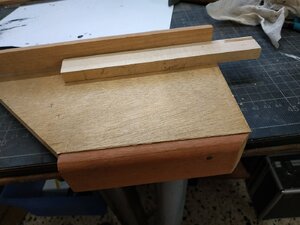
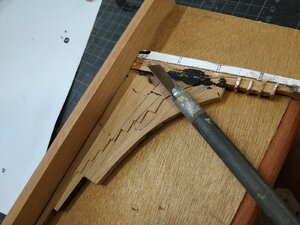
Last night dreamed about shaping the Rabbet with the chisel blades- the part stabilized on a board with lips in alternative directions -one as a stop for the part, other to hook the table edge. Obviously my brain works better when asleep. So after first reinforcing the joint sternpost/deadwood with trunnels, I made this.
While drying, returned to the rising wood-match scarph to apron, sand the slope and (black)glue to keel. the middle piece is then fitted. The aft piece is left until after the ster assembly is fitted to the keel.
Again the 3D is helpful for visualizing blending the bevel onto the innerpost. Used the chisel blade and it did work nicely, and then finish with sanding stick.
Remove the glue and paper and generally clean up. Broke off a step, found it and glued back.
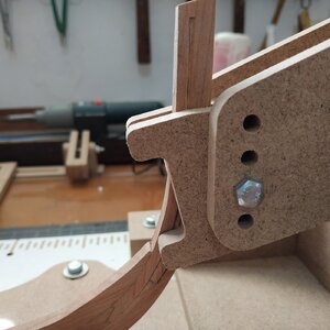
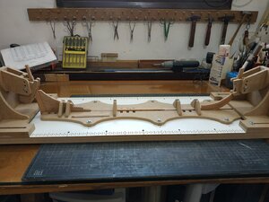
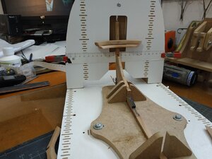
Now to attach the stern assembly to the keel. To ensure alignment , at last I get to use my new building slip that I ordered from Poland earlier this year.
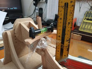
Using the pins previously placed in the keel, the stem is located correctly (glue previously applied) and held in the building slip to ensure it is vertical. The last part of the rising wood is fitted .
When all dry, trunnels from bottom or keel into the stem. The rising wood checked that joints are level.
Now I put the rabbets in the stem, leaving 5mm unmade at upper extreme, and joining the horizontal rabbet already made.
I have always found a curved rabbet difficult, mainly because of the grain of the wood.This cherrywood is somewhat "soft", and control of any cutting tool is difficult. In retrospect, I should have braced it against an appropriate French curve, but I wasn't sleeping and didn't dream what to do.
Slowly, gently scored the wood with a 1mm "ball" bit held in mini drill. Then enlarged with tip of small (3mm) round file. Tried scalpel blades as suggested, but didn't work for me . Maybe me, maybe the character of the wood. I will leave the final shaping until I try out some planks.
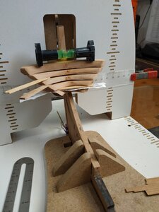
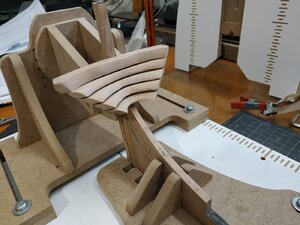
TFFM states then shows an elaborate jig some else made to align the wing transoom. By changing the height and rotating the stem holding piece of the building slip, it fortuitously can be made to support the wing while clamping the stern.Cover with some cling film to stop glue sticking the wrong bits. The joint is double checked in all directions, downward slope, horizontal and at right angle to the stem. Check height at wing tips at both sides -11.45mm as stated in TFFM and the plans. A miracle.
****The wood darkens rapidly after sanding or scraping. I don't want to use oil or lacquer or poly at this stage. Thought about shellac and the scraping when gluing surface is needed, Never had this problem before (or never noticed it) but the fresh wood is a lovely beige and ages quickly. The old uncut wood is really quite dark. ?Will treating the fresh wood prevent this or will it happen any way?17g.jpg17e.jpg17.jpg17f.jpg17d.jpg17c.jpg17i.jpg
 

Attachments

  • 17a.jpg
    17a.jpg
    229.5 KB · Views: 22
  • 17h.jpg
    17h.jpg
    252.9 KB · Views: 22
Here's a link to Admiralty Models and their 3-D rendering of a Swan Class ship. Everything included in TFFM. Really nice and may be helpful. The photo is the stern deadwood and stern post.


View attachment 179496
That's true . I bought it ( 3D computer rendering)about 6 months ago. Unless you can read plans directly, I think this is an essential tool for this and any similar build. Considering the overall cost of scratch building- basic plans, additional plans, practicums or books, special electric tools etc.- the cost is fully justified.
 
I forgot about my 3mm Rifflers (? too many tools-impossible-or age memory lapse). Ideal for finishing the Rabbets.
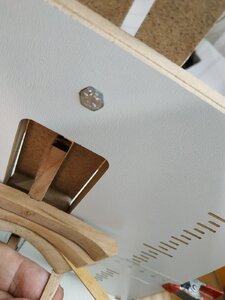
Using the horizontal alignment of building slip, I fitted the 1st filling transom. The tips of the wing transom almost touch its upper surface. There should be about another 1mm gap. Can't find error. Will leave for the moment and if it becomes apparent this is critical I'll figure out how to adjust (or cheat). I fixed with trunnels now because I want stability so as to use spaces between this and lower transom.
When sure position ok and stable, use equal shims to settle the next transom. The width seems equal and appropriate, and equalised "rotation" or foreward position with simple depth "gauge". Keep eyeballing all directions for symmetry.
Transom #3 - elevation angle too high. Requires adjustment to the step.
Transom #4- I now see that too much excess at top of deadwood was removed, and now needs extra height-a thin filler.
Now obvious that the port wing of of #2 transom overlong. Leave shims in place to sand all lateral faces when fully stable with glue and trunnels. 18b.jpg18a.jpg18a.jpg18.jpg18.jpg
 
I forgot about my 3mm Rifflers (? too many tools-impossible-or age memory lapse). Ideal for finishing the Rabbets.
Using the horizontal alignment of building slip, I fitted the 1st filling transom. The tips of the wing transom almost touch its upper surface. There should be about another 1mm gap. Can't find error. Will leave for the moment and if it becomes apparent this is critical I'll figure out how to adjust (or cheat). I fixed with trunnels now because I want stability so as to use spaces between this and lower transom.
When sure position ok and stable, use equal shims to settle the next transom. The width seems equal and appropriate, and equalised "rotation" or foreward position with simple depth "gauge". Keep eyeballing all directions for symmetry.
Transom #3 - elevation angle too high. Requires adjustment to the step.
Transom #4- I now see that too much excess at top of deadwood was removed, and now needs extra height-a thin filler.
Now obvious that the port wing of of #2 transom overlong. Leave shims in place to sand all lateral faces when fully stable with glue and trunnels. View attachment 179576View attachment 179577View attachment 179577View attachment 179578View attachment 179578
Hello Stuglo, Great job you are doing on your Swan Class Ship. I find this type of ship very interesting and there is no limit on the amount of detail that one can add to these ships. Will fowl with great interest.
Regards Lawrence
 
hello Stuglo, what a pleasure to watch your post. super great execution. Craftsmanlike > 1st cream !! simply fantastic. One can learn so much with you. thanks for that
 
22/9/2020
some trimming-sanding- especially port #2 transom. Surprisingly they then line up pretty well.
Return to finishing the stem head- seating or groove-diameter of bowsprit at this level giving a model size 9.8mm
The angle (TFFM) can be found by taking line (and dowel)from a point about 22cm from aft of foredeadwood.A sanding attachment of 9.6 diameter gave a good start for this groove. A 8mm dowel with a wrapping of sand paper finished the job. Note that the depth is LESS than the radius as the width extends into the surrounding knightsheads.
(The large appendix on milling the transoms cant frames and associated parts, as well as several jigs. Perhaps if I were 10 years younger, with time and patience to learn, I would try it. )
22e.jpg

22d.jpg
 
Last edited by a moderator:
Very nicely done. A quick question, where did you find the white board with the inches marked out?
Thanks, Dennis
 
Finished chapter 1 TFFM- Chapter 2 starts with referring back to 1/11 ch.1 (progress).
Again check alignment and fixation of transom. And again the building slip shows its worth.
Encouraged to read ahead into the chapter, but find it complicated and confusing. If I hadn't encountered this sort of situation many times before, I would be discouraged. I resolve to take each step at a time (It can always be redone if subsequently found to be in error--never lose heart)
I check the Kevin video- he goes for making the aft cant frame first. But I was lucky with my scarphs and decide to go ahead with the aft fashion piece first and see how this works out.
First, in order to position and align parts, the breadth plans must be fixed for and aft. The alignment of these must be taken by comparing the fixed points on the sheer plan. NOTE- the aft point on the breadth plan is not the same as at keel level due to its backward slope. I estimated this point is 11mm further aft from end of keel and fixed the aft plan using this reference point.
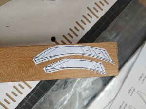
The fashion piece blanks are 4.77mm
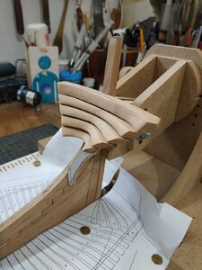
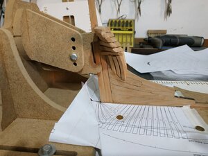
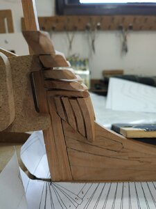
Tried the 29.5 deg angle with the band saw -not so easy to control a bit to give a smooth edge. Tried the 5in disc sander with table set at just under 30- pretty crude estimation- and it works beautifully. The "foot" fits on the aft of the last step. The height and angle by trial and error ( nice words for keep shaping/cutting/sanding until too small, then make the next one slightly bigger!). Minimal shaping of bevel (aftwards)-correction later together with other parts. Attention to fore position under fore point of #4 transom and checking with sheer and breadth plans and eyeballing from front. Some slight gaps, probably hidden but see how it all looks when others are made. The function of these pieces seem to support the transom and give fixing purchase to the planks, As made, they seem fit for purpose.
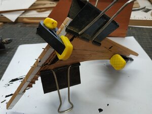
It took a while for me to understand that the other filler pieces are non-specific and just fill in the gaps aft of the aft fashion piece, and the same pattern can be used for the. Note they sit on the curve (shape foot accordingly) and are shorter. While keeping the 29.5 angle, the VERTICAL angle can be adjusted so the piece leans inward so more underneath the #4 transom. After fiddling, in all directions, too much removed, make a copy a bit longer for this,22b.jpg22a.jpg22.jpg and use original for the next (higher) one!
 
Fitted rest of the filling pieces- smaller than expected but seem OK
Now to the aftermost cant frame. TFFM says "the moment you have been dreading". Its worth stating the obvious- the longer the explanation, the more complex/difficult the build. We're given some alternatives, and Kevin's video shows he built it all in one piece. Easy first- the wood thickness 4.77mm represents the WIDTH. I'm going to try the chock option. I must say that it has taken me 2+hours to read, reread and try to understand this stage.
Cut the outline pattern of lower futtock and realised immediately a mistake. I cut the "lip" where the chock is to be joined, without allowing fore the chocks bevel. Remake with "square" 90deg to curve. Will shape lip later. After some puzzling, I think this bevel is such that futtock side is thinnest uppermost.
To help with bevel, I stick the mirror image to the other side after shaping to the outside lines. This time I found that the mirror images I made on my printer we slightly but significantly bigger. Go to reprint to better size and suddenly the printer decides to play silly buggers. My brain is exhausted from too much thinking (worked this morning) -can't figure out an easy fix. I'll just shut it and me down for the day.25a.jpg25.jpg
 
I forgot about my 3mm Rifflers (? too many tools-impossible-or age memory lapse). Ideal for finishing the Rabbets.
Using the horizontal alignment of building slip, I fitted the 1st filling transom. The tips of the wing transom almost touch its upper surface. There should be about another 1mm gap. Can't find error. Will leave for the moment and if it becomes apparent this is critical I'll figure out how to adjust (or cheat). I fixed with trunnels now because I want stability so as to use spaces between this and lower transom.
When sure position ok and stable, use equal shims to settle the next transom. The width seems equal and appropriate, and equalised "rotation" or foreward position with simple depth "gauge". Keep eyeballing all directions for symmetry.
Transom #3 - elevation angle too high. Requires adjustment to the step.
Transom #4- I now see that too much excess at top of deadwood was removed, and now needs extra height-a thin filler.
Now obvious that the port wing of of #2 transom overlong. Leave shims in place to sand all lateral faces when fully stable with glue and trunnels. View attachment 179576View attachment 179577View attachment 179577View attachment 179578View attachment 179578
Hi stuglo. Nice job on the dead wood and transom. Great build and I should get some good ideals watching your build. Gary
 
Back
Top