Didn't send any photos today.something is not working with the photos of this post - maybe you edit and post them once more - Thanks in advance
-

Win a Free Custom Engraved Brass Coin!!!
As a way to introduce our brass coins to the community, we will raffle off a free coin during the month of August. Follow link ABOVE for instructions for entering.
-

PRE-ORDER SHIPS IN SCALE TODAY!
The beloved Ships in Scale Magazine is back and charting a new course for 2026!
Discover new skills, new techniques, and new inspirations in every issue.
NOTE THAT OUR FIRST ISSUE WILL BE JAN/FEB 2026
You are using an out of date browser. It may not display this or other websites correctly.
You should upgrade or use an alternative browser.
You should upgrade or use an alternative browser.
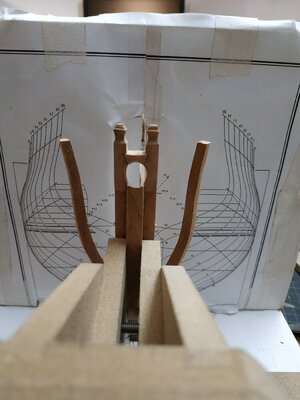
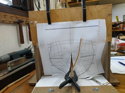
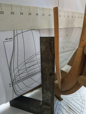
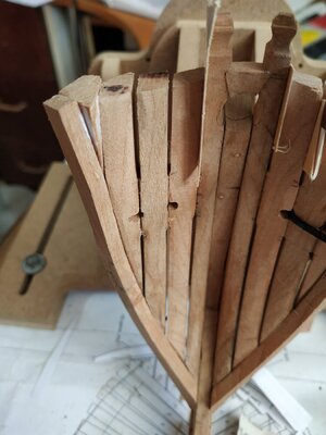
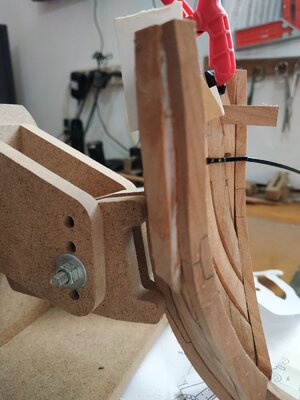
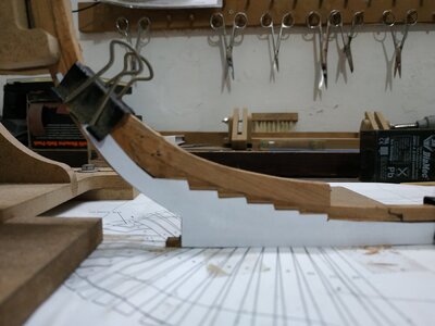
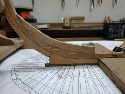
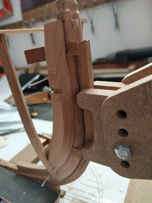
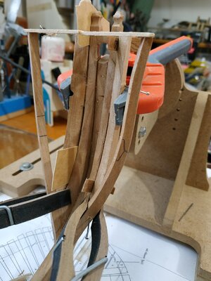
you see theseCleaned up bridging chock to blend with bevel of timberheads- looks OK to me.
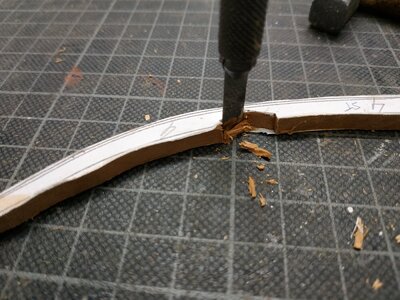
.......Anyway separated at joint and needs repair...........
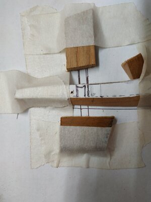
View attachment 184713View attachment 184714View attachment 184715View attachment 184716View attachment 184717View attachment 184713View attachment 184714View attachment 184715View attachment 184716View attachment 184717View attachment 184718
later that night......
So as not to leave my friends in suspense, will give an update.
Decided to try and remove (again) the 1st cant and the timberheads with bridging block as a whole. Success. Marvelous how alcohol helps a problem.
The steps are the main problem and using a cutout against the keel, reconfigure with new chisel blade. 2+mm removed . The slightly thicker lower stem is corrected for at the same time as it contributes to the height of the steps.
Lessons to be learned: (mostly obvious therefore relearned)
At every stage, check,measure,check remeasure again.
Check against whole plan not just part.
If something is wrong find out why and fix it.
I initially thought to leave the problem and compensate with a later -this is laziness and a recipe for disaster. At the least, dissatisfaction or at worst (God forbid) abandoning the project .
There are plenty good people out there only too willing help-listen to their advice.
Now we can all rest easy
Goodnight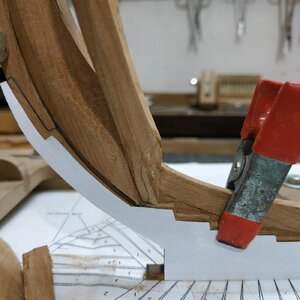


Hello Stuglo,
I follow your work with great interest. I like it extraordinarily. Thumbs up.
I follow your work with great interest. I like it extraordinarily. Thumbs up.
15th and 16th Oct.
(originally tried to post on friday, but after writing it all out, deleted instead of submit - "you pressed the wrong button,bacon brain"-Miss Piggy)
Anyway, with timberheads removed, reduced the height of stem/bowsprit grove to its high point of 14.5mm (using the sliding sander)
Reposition timberheads with reference to aft aspect of rabbet and lower foot . Luckily (rabbet's foot-ha!ha!) reworking to follow curve is easy. The bowsprit aperture remains the same. Although the bridging chock remained in place, each side needs to be aligned separately. New pin guides are needed.
Result is my timberline is 2mm higher than the plan- ? good enough.
Refit 1st cant -had to reread TFFM as forgotten already although it was only a few days ago.
I had to add a slim shim to "sole" of timberhead . This wood has quite a marked grain pattern so as long as additions are in parallel, they blend very well. In any case, most will be hidden. Probably just me and my conscience know and care.
As others have remarked, surprisingly small changes/variations can have significant effects. On the other hand, wood can be very forgiving and adaptable - don't be frightened dismantling and making corrections.
At last, returning to #2 hawse piece:
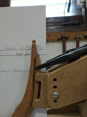
The lower part of the opening is at 11.8mm -just 1mm below the markings on my cut out plan. Go with TFFM and use the master plan reference.
As advised, place the upper locator pin below the are which will become the air space (about 4.24mm above hawse hole).
Good and detailed advice about how to file the groove. No so simple as I have a tendency to "rock" and the groove dips ao one or both ends).
Extend lines on copy fore area, place piece lining up the rabbet and clamp both to table. Given the thickness of the piece and wanting to form groove of depth 3.18mm, blocks of thickness 5.25 were taped on either side.
This groove is 2/3 of total (its neighbour #3 is 1/3). My file is 3.17 diam.-the depth of the groove. So when to top is flush with the piece, I've done the job.
The clamping to the table and the direction (slope) outlined on the plan, make this much easier.
My next problem is how to widen the the diameter of the groove to 3.98mm but I do not have a 4mm file. I'll proceed and think of a solution later (or some kind reader can tell me).
The piece has upper and lower air spaces on inner and outer faces- the lower at same height as its partner on the timberhead (and extending to end of piece) the upper starting 18mm above it.
The required 0.4mm is removed by milling -ensuring the parts are supported by a 0.4 shim when milling the second side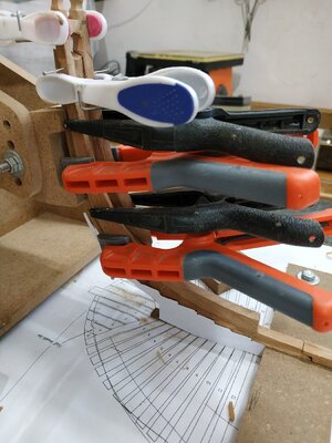


I’m enjoying your progress. I’d like to do a swan class stern cross section one day!
Wasn't 100% happy with situation and was undecided whether to start again and remake the last few pieces. This morning things looked a little better and decided to go ahead , finish the #2 hawse pieces and fit them.
When aligning the levels of groove and air spaces, not only check against parts already fitted, but against each other (they should mirror exactly).
Assuming the guide pins already prepared (if not temporarily rubber glue in place so as to drill for guiding pins , as otherwise it moves so easily). Also remember to place the spacers (in this case, 0.8 below and 0.4 above) then glue the thickness not milled plus the foot. Locate the pins (not so easy as is usually) and clamp CAREFULLY so as to avoid slippage.
I think it obvious, but do one side at a time and only after glue dry, replace pins with trunnels, and then go to other side.
Hawse #3A
Apparent problem- book says blank of 14.5in (7.69mm) but detail on plan says 14in.
There is a diagram of the overall width at this stage in the book 95in. deduct the #3 and left with 29in-for pair. Thus 14.5un is correct. I then notice piece #4 is 13.5in in book but 14in on plan- so in the end will have same result. Nevertheless, I'll go with the book (15,14.5,14,sounds better than 15,14,14,)
Note, the bevel is still 34.5.
**PS**
Don't eat chocolate cake with fingers when handling wood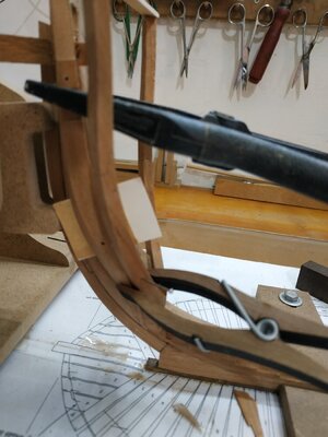


Thanks. I see you like the bigger scale. Quite right. I made Hannah at 1/48 as a learning exercise but I felt that as a model, the larger scale would give better potential and final result .I’m enjoying your progress. I’d like to do a swan class stern cross section one day!
I remember seeing a thread about the magnification necessary to go from 48 to 32, that it wasn't simple +50%- how did you upscale?
The 1:32 scale is 150% of the 1:48 scale. 1:48 is 1/4” = 1’, 1:32 is 3/8” = 1’
Hello Stuglo,
your workis very impressive. I like it very much, I'll keep at it.
your workis very impressive. I like it very much, I'll keep at it.
Checked accumulated max. width of 2xhawses #1and#2, 34.76mm instead of 34.98 -I can live with that.
Hawse piece #3
As same bevel as before, at the foot, and outer surface from fore edge. Align this edge with the aft edge of#2, spot rubber glue T foot and where grooves will be.Remember the 0.4 spacers. While stable, holes for guide pins again avoiding air spaces. Mark aft edge of #2 on inner surface#3. I will bevel this later so the piece will be more stable.Mark grooves fore and aft. corresponding to their neighbour on #2. . This time they match the pattern. Similarly mark levels of air spaces.
The groove is only 1/3 of depth as its neighbour-1mm
Again clamp on plan with extended lines of hawse holes, to table. The same 3mm file- and I get to use my new depth gauge.
A similar groove is made on other side and parallel.
Recheck airspace marks, and mill to within a couple of mm, taking off a depth 0.4 . Remember to use this depth shim to support piece.
Extend the airspaces to marks and finish with 45deg incision as before.
Glue to neighbouring #2 either side of groove, and at foot to cant. Ensure spacing with 0.8 spacers.
About to glue second pieced and-WAIT. Something's not OK
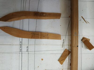
The piece has lost weight- its too THIN.
Check- only 4.68mm not 7.69mm (!@#$%^&*-expletive)
?How . Must have picked up the wrong blank when resumed work . Perhaps more used to the size of cants than hawses.
? Senior moment. My wife says I did stupid things even when a youngster-I can't remember.
Anyway- good lesson- if it appears to be going well-see where you are going wrong!!!!
Start again tomorrow.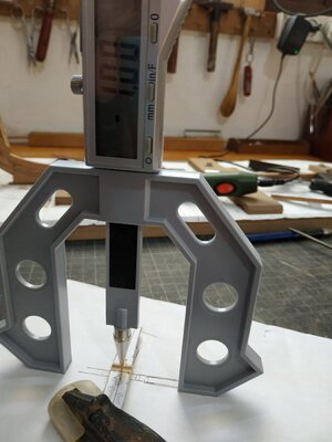


21st oct
back to hawse #4
Stock 7.16mm as per book(not plans)
Tramlines on plans help orientate piece for bevel - again 34.5deg.
Looks weird -a twisted orange segment. Try out dry fitting starboard side- doesn't fit in properly- not "deep" enough. Why?
So remade piece and same result.
Start rechecking everything. The other hawse pieces are also "proud" I had left some extra for sanding down later. ? The 1st cant. Check with cutout- seems ok. Make a one piece cant#2 for comparison- lines up o.k. Recheck against breadth plan -also seems OK
Think. ?what determines the depth relative to the cant- amongst others, the fore margin against the aft of the preceding piece. I tend to leave a about 0.5 mm margin to compensate for my tendency to include the line.
**Its like old age, too much in the wrong place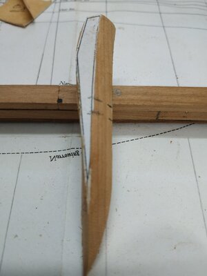
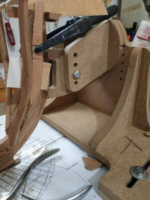
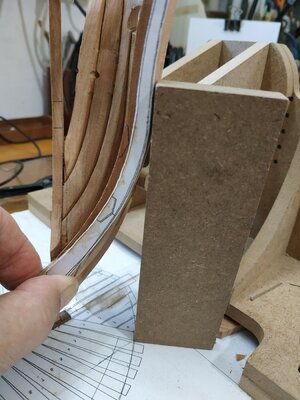
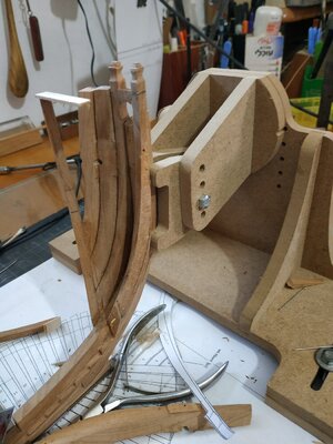
 **
**
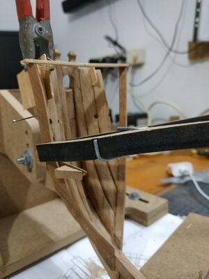
Anyway, separated all starboard hawse pieces (alcohol +chisel blade) except my bridging chock (couldn't face making that again) and using fresh cutouts, refined the lines and reglue. Better.
While waiting to set make and trial fit #4 (this side seems better so will asses after this fit rather than take everything apart )
Seems not to bad.
Lessons: to be relearned again and again- precision and check all parameters in all dimensions. If it doesn't look right ,it probably isn't. This is not a steep learning curve. It is not jazz (improvisation) or impressionism, but the discipline to keep EXACTLY to the plan. Vary the technique (tactics) but keep to the goal (strategy) -if I'm using the terms correctly.
back to hawse #4
Stock 7.16mm as per book(not plans)
Tramlines on plans help orientate piece for bevel - again 34.5deg.
Looks weird -a twisted orange segment. Try out dry fitting starboard side- doesn't fit in properly- not "deep" enough. Why?
So remade piece and same result.
Start rechecking everything. The other hawse pieces are also "proud" I had left some extra for sanding down later. ? The 1st cant. Check with cutout- seems ok. Make a one piece cant#2 for comparison- lines up o.k. Recheck against breadth plan -also seems OK
Think. ?what determines the depth relative to the cant- amongst others, the fore margin against the aft of the preceding piece. I tend to leave a about 0.5 mm margin to compensate for my tendency to include the line.
**Its like old age, too much in the wrong place


 **
**Anyway, separated all starboard hawse pieces (alcohol +chisel blade) except my bridging chock (couldn't face making that again) and using fresh cutouts, refined the lines and reglue. Better.
While waiting to set make and trial fit #4 (this side seems better so will asses after this fit rather than take everything apart )
Seems not to bad.
Lessons: to be relearned again and again- precision and check all parameters in all dimensions. If it doesn't look right ,it probably isn't. This is not a steep learning curve. It is not jazz (improvisation) or impressionism, but the discipline to keep EXACTLY to the plan. Vary the technique (tactics) but keep to the goal (strategy) -if I'm using the terms correctly.
Continuing to work on hawse #4 last week, the port side seemed fair but left a peculiar space for the filler. The starboard wouldn’t fit at all. Rechecked the 1st cant against the breadth plan and found that somehow the angle and therefore the distance between timberheads had narrowed considerably. I think this may have been due to the use of spring clamps that exerted too much pressure.I unglued and separated all the hawse pieces and cants.
(A BLUNT blade is better for this.)
Having separated the cant several times they look a bit worse for ware- so remade them.
The hawse pieces needed cleaning up and fortunately able to separate and reuse both bollard timbers and their bridging chock.
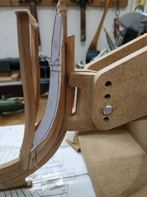
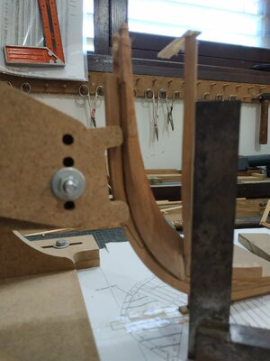
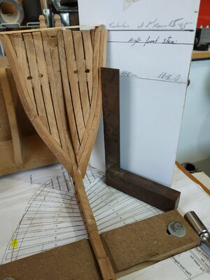
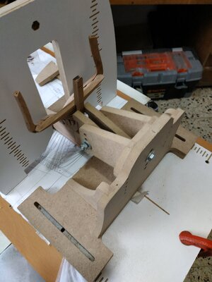
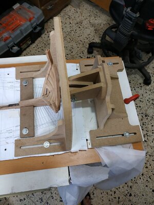
Used my jig to hang the relevant part of the body and align the timberline of the cants while using set squares to check against the breadth plan.
As Richard Feliciano mentions, the relation to the step is secondary.
Remade starboard hawse#2 as old was damaged when removed.
Wore out 3 small files (and hurting shoulders) making grooves so thought there must be a way to machine these.
** Angle marked as before, held vertically in vice with so direction becomes 90deg, using 3mm milling bit much like a drill press, but incrementally moved until depth required. Quicker and cleaner groove.
Hawse#3 both OK
At last back to hawse #4 (taken me 4 days to get here).
Blanks of 7.16mm
Even with the tramlines as advised (to ensure vertical angle of short bevel) not easy.The starboard worked first time, but the port was more difficult as use same side as disk sander but at opposite angle. Took 3 attempts. After that it's the same principle bevels, but leaving the weird shape. Who cares-it fits!!
Tomorrow the filler pieces.
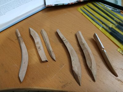
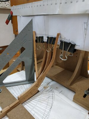
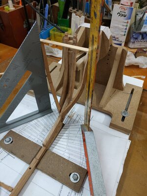
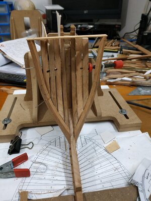
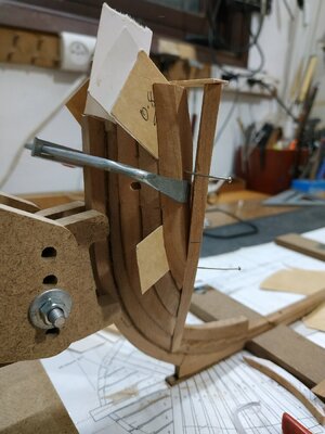


The filling pieces.
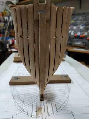
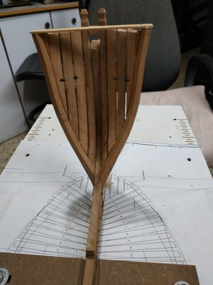
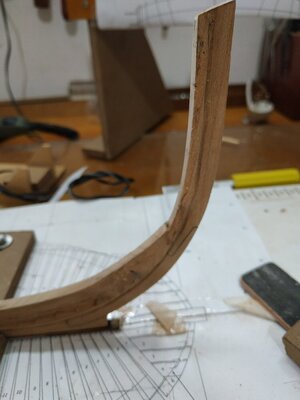
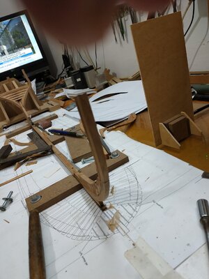
Some specific measurements are given to make an oversize plug to fill the gap between the #4 hawse piece and the 1st cant. It should be dagger shaped with a cross section triangular shape. Couldn’t really see from the diagram how to do this, so took a spoiled hawse piece and shaped one side (length) to the 34.5 bevel so as to match the cant. The importance is to match the “back”. Then trial and error with the hand-held band sander, shaped until fit. The much larger than necessary piece of wood allowed for lots of trial and error. Anyway, it seems to work for me. When fitted and dried, the fore shaping can be fought out. The whole structure isn’t particularly rigid, so have left finishing inside and out until later in the build. The 1st cant remains in its appropriate position.
Some specific measurements are given to make an oversize plug to fill the gap between the #4 hawse piece and the 1st cant. It should be dagger shaped with a cross section triangular shape. Couldn’t really see from the diagram how to do this, so took a spoiled hawse piece and shaped one side (length) to the 34.5 bevel so as to match the cant. The importance is to match the “back”. Then trial and error with the hand-held band sander, shaped until fit. The much larger than necessary piece of wood allowed for lots of trial and error. Anyway, it seems to work for me. When fitted and dried, the fore shaping can be fought out. The whole structure isn’t particularly rigid, so have left finishing inside and out until later in the build. The 1st cant remains in its appropriate position.
Very good work - it is looking very good 

Very beautiful and accurately worked. I like it very much. Chapeau.
Fore Cant Frame #2
Need to review how to make cants -back to instructions for aft cant in TFFM.
All cants are 4.77mm wide. Remember that the other “direction” will be the inner and outer hull surface, so extra will be removed later with hull sanding.
Decided to try again with the chocks- in any case shorter blanks are far less wasteful.
With#2 the bevel of the chuck is minimal. So I cheated. Made it as one piece, chiseled the chock out, and reassembled it. Looks o.k.
Triple check bevel angles, each is different. #2 is 32.5degs
TFFM also mentions additional small bevel at foot because the angled foot is wider than - I tried this before gluing, but insufficient, so remove some from base #1 can with a chisel It's easier after gluing so with do this with the rest of ribs as required.
Trunnels(staggered pattern as suggested). Hold in piece vice for position and “verticality”and use drill press.
Trunnels oversize at 0.7mm, but I want to see them. (also difficult for me to make smaller)
Fit, check “foot” doesn’t overstep step.If necessary pare back by beveling neighbouring #1cant foot (very slightly).
Glue,hold in place until holds up by itself, and adjust the angle so vertical (square) and alignment with the timberline as on the breadth plan ( previously made height card and holder).
Keep rechecking position maintained while glue dries( present weather, 5-7 mins)
Repeat for port twin.
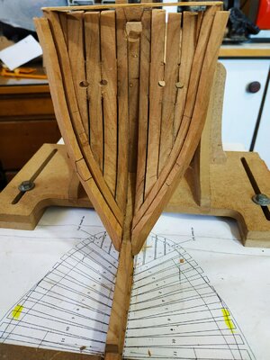
They look symmetrical, so probably OK.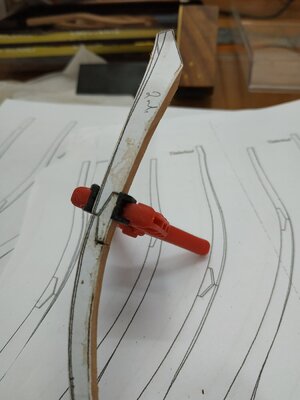
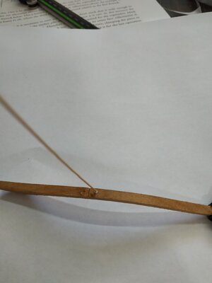


Just worked my way through your great log (while listening to the Tijuana Brass). Very impressive build.
Jan
Jan
# 3 fore cant
Relatively simple with 30drg. Bevel, shade area to be removed-phone call- come back and remove the wrong bit!@#$%^
Relatively simple chock (joke)
While busy fitting the fore cant (various squares-made both a shorter and taller ones-the latter weighted with a epoxyed battery), the aft cant snagged my elbow (damn attention seeker)
Glued it back and because not first time, protected it with the building slip vertical board.
#4 fore cant- again change of bevel angle. (27)
As previously noted, some beveling of the foot, so it can fit on step.
#5 ditto except angle now 22.5deg
#6 ditto, angle now 19 deg
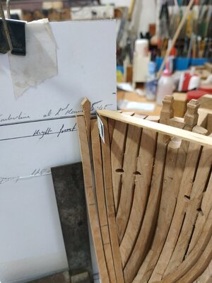
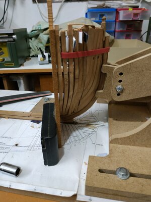
Suggested by TFFM to make temporary wedges, but want something even more temporary, while check, recheck and recheck all alignments and relation. So after horizontal bracing (glued) used folded card to separate at timberline level and NOTtight rubber band.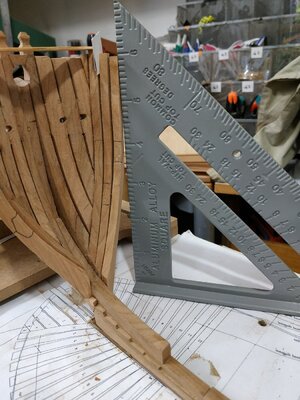


