Swan Class – ¼” Scale - Stuglo [COMPLETED BUILD]

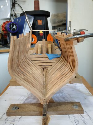
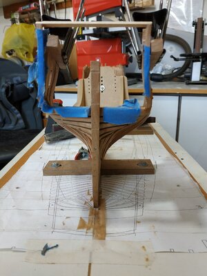
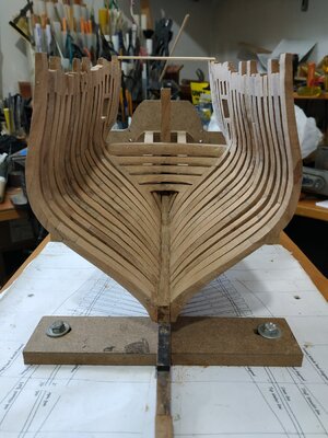
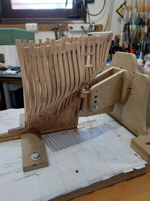
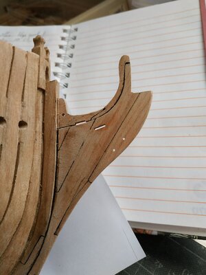
Framing the stem/side Counters
(TFFM mentions a 9th port- at present this would be an unnecessary complication and I’m still on chapter 2.)
The practicum gives a detailed explanation which encourages reading to the end. I don’t really understand, so I turn to Kevin’s video-he says something similar, so we go ahead and make the pieces.
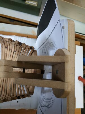
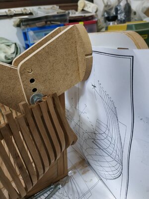
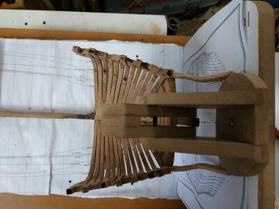
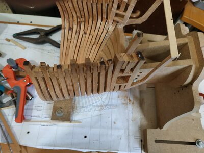
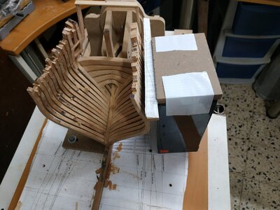
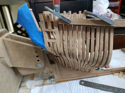
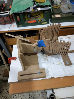
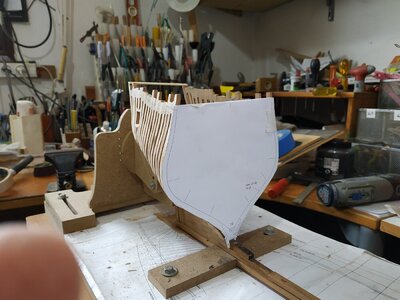
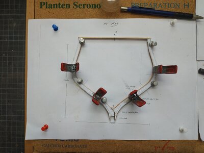
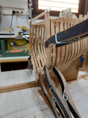
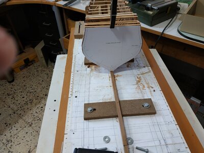
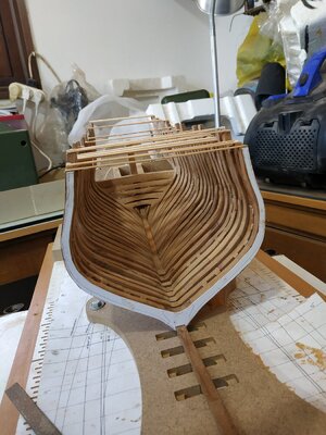
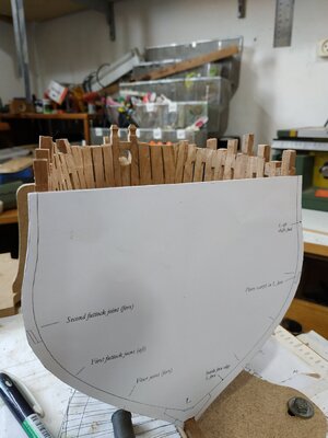
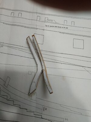
Before attempting to make the piece, a jig of some sort needs to be made to align and support the aft end, at the correct height, and angle so the pieces are separated by the correct distance. Additionally, the stem needs support to maintain the vertical 90deg position.
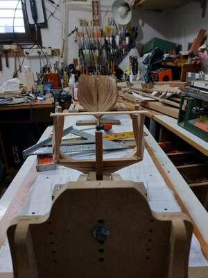
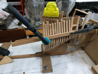
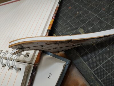
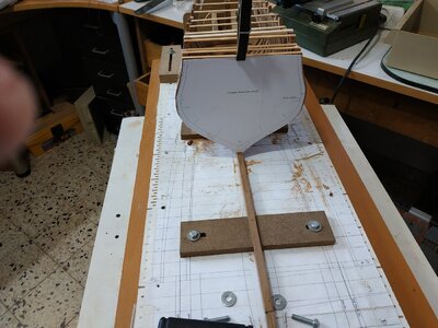
The hobby building slip has a vertical plan holder. By adding the stem clamp to this (with the body plan underneath)it supports the stem, the new side counter while controlling its position and angle.
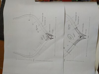
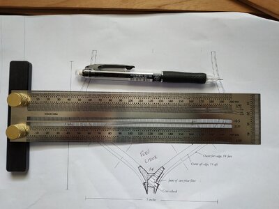
Instructed to draw line parallel and 3.34cm aft of AP line on the breadth plan. This intersects with the end of the timberline and is aft position of the pieces and the mark for the vertical plan holder.
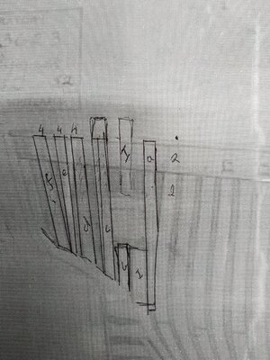
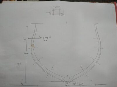
On the body plan, vertical lines, 3.9 cm either side of the midline are drawn and the point this intersects with the height of timberline, is marked.(A simple drawing on the page makes this very simple).
Fortunately the book gives a (correct 1/48)scale image because I spent a half an hour searching the plans.Note this is for the starboard side - it took me a while to be sure of this.
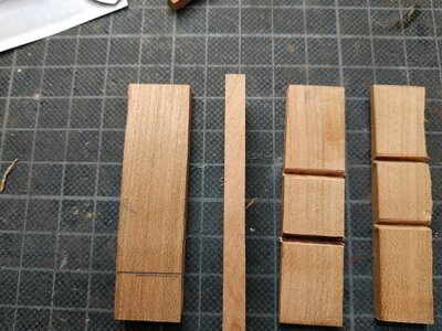
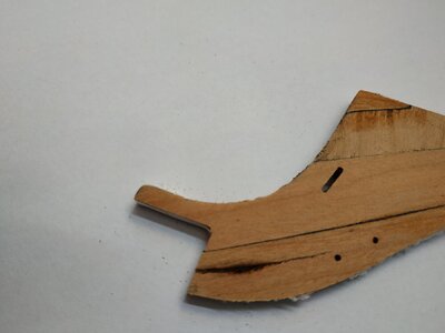
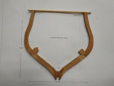
Photocopies for templates, 7.95mm blanks, and using the sanders, made the pieces in 2 stages ie dimensions.
The timber line is marked on the pieces and the inner aspect aligned to the mark on the plan (again the drawing in TFFM is self explanatory)
The “foot” needs some refining to accommodate angle of #1 cant and slope of wing transom.
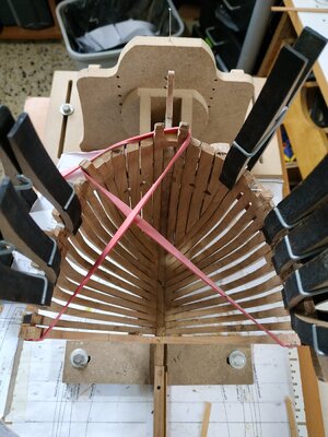
This is (if only temporary)a fragile joint so I used 5min epoxy while the plan holder supports the end and vertical plane is maintained.
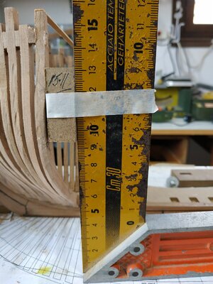
An additional measure is used- 9.22 cm between the 2 upper knuckles-this is checked while glue is still semi-flexible.
Finally, if sure OK, a spall or beam is temporarily stuck to the tops for additional stability.
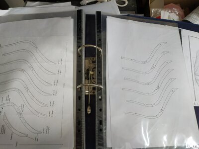
PS accumulating lots of photocopies of part plans/templates. Filing them in separate plastic envelopes in a file makes for order.1612b.jpg1612c.jpg1612d.jpg1612e.jpg1612f.jpg1612.jpg
 
Finishing side framing and Fairing same:
Just 2 short paragraphs and little explanation for what turned out to be a long and frustrating stage.
This stage includes the forming of the stern lights (window).
Position, angle and size from the framing plan.
The upper part of 1st aft cant needs to be cut off at the appropriate height (cutting a part off the hull is always traumatic for me).
An extra “limb” attached to the fore side forms the fore side of the window-the other (aft) side is one of the “fillers” that sit on the counter frame.
The upper cant frames learn forward-this slopes back and 2nd cant frame at an angle therefore cut as a blunt-ended wedge.I decided not to glue in place yet so that I could build the window on the plan before fitting.
This,like the other fillers, follow the line of the aft cants but as no patterns are available, I used wide blanks (15mm) and for the most, kept them the same thickness of the other cants.
The aft side of the window sits on the counter frame, parallel to and at a distance shown on the framing plan. The angle of the sills is also shown.
The position of the sills marked with on the side frames-
Not clear from the plan the thickness of sills, so I guessed at 3mm lower and 2.5mm upper.
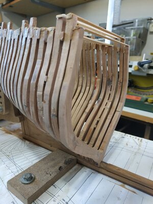
The TFFM shows a “v” shaped mortise for lower with a variant for upper joints.
I thought I’d be clever and use a “V” milling bit to a depth of 1.5 and widen the V with the chisel but with my defective thumb I found this impossible. So I cheated and used a square ended bit with a width of sills.
Forgive me.
The other fillers caused me more difficulty than anticipated.
Balanced on the thin counter frame they needed the small fillers at the top to be held in place while drying. Keeping alignment was anticipated thus the excessive width of the blanks.
There is also some variety of thickness-again referencing the framing plan.
Angling correctly the “feet” was fiddly and lack of patience on my part (fatal for a modeller) caused frequent dislodging of bits.
Also an overly tight wedge between two tops, caused one of the counter frames to part from the wing transom.
This necessitated unsticking the adherent bits, realign the counter frame as before, and start again.
The PVA glue has a fast grip, but be left overnight for good adherence.
Fairing:
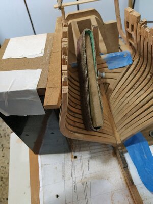
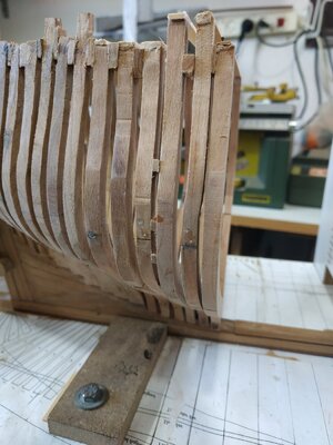
Because of the extra wide fillers, window frames and sills, lots to take off. So I used the hand band sander for these.
The rest of the sanding was time and effort and I’m sure any modeller is familiar with this.
Just to emphasise the need to support the work -by hand and clamped beams.
I again left the lower external fairing until keel more stable.
These stages have taken me more time and frustration than anything so far. Perhaps the designation ”filler” suggested something simple and I didn’t give the attention and respect needed
I’ll try not to repeat this mistake.(Modelling is like life-nothing is as simple as it seems)2412.jpg2412a.jpg2412b.jpg2412c.jpg2412d.jpg2412e.jpg2412f.jpg2412g.jpgIMG_20201229_081539.jpgIMG_20201231_080017.jpgIMG_20201231_080036.jpg
 
Finishing side framing and Fairing same:
Just 2 short paragraphs and little explanation for what turned out to be a long and frustrating stage.
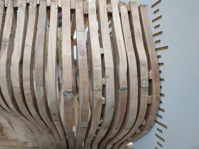
This stage includes the forming of the stern lights (window).
Position, angle and size from the framing plan.
The upper part of 1st aft cant needs to be cut off at the appropriate height (cutting a part off the hull is always traumatic for me).
An extra “limb” attached to the fore side forms the fore side of the window-the other (aft) side is one of the “fillers” that sit on the counter frame.
The upper cant frames learn forward-this slopes back and 2nd cant frame at an angle therefore cut as a blunt-ended wedge.I decided not to glue in place yet so that I could build the window on the plan before fitting.
This,like the other fillers, follow the line of the aft cants but as no patterns are available, I used wide blanks (15mm) and for the most, kept them the same thickness of the other cants.
The aft side of the window sits on the counter frame, parallel to and at a distance shown on the framing plan. The angle of the sills is also shown.
The position of the sills marked with on the side frames-
Not clear from the plan the thickness of sills, so I guessed at 3mm lower and 2.5mm upper.
The TFFM shows a “v” shaped mortise for lower with a variant for upper joints.
I thought I’d be clever and use a “V” milling bit to a depth of 1.5 and widen the V with the chisel but with my defective thumb I found this impossible. So I cheated and used a square ended bit with a width of sills.
Forgive me.
The other fillers caused me more difficulty than anticipated.
Balanced on the thin counter frame they needed the small fillers at the top to be held in place while drying. Keeping alignment was anticipated thus the excessive width of the blanks.
There is also some variety of thickness-again referencing the framing plan.
Angling correctly the “feet” was fiddly and lack of patience on my part (fatal for a modeller) caused frequent dislodging of bits.
Also an overly tight wedge between two tops, caused one of the counter frames to part from the wing transom.
This necessitated unsticking the adherent bits, realign the counter frame as before, and start again.
The PVA glue has a fast grip, but be left overnight for good adherence.
Fairing:
Because of the extra wide fillers, window frames and sills, lots to take off. So I used the hand band sander for these.
The rest of the sanding was time and effort and I’m sure any modeller is familiar with this.
Just to emphasise the need to support the work -by hand and clamped beams.
I again left the lower external fairing until keel more stable.
These stages have taken me more time and frustration than anything so far. Perhaps the designation ”filler” suggested something simple and I didn’t give the attention and respect needed
I’ll try not to repeat this mistake.(Modelling is like life-nothing is as simple as it seems)View attachment 202796View attachment 202800View attachment 202801View attachment 202802View attachment 202803View attachment 202804View attachment 202805View attachment 202806View attachment 202807View attachment 202808View attachment 202809
Your insistence on accuracy and beauty, has paid off and indeed the result is simply extremely impressive and worthy of great appreciation. I salute you dear friend
 
Knee of the Head
(my dyslexic son referred to the ”elbow in his leg“ instead of knee)
The good news is that we finished chapter 2 (TFFM)!!!
This is a set of seemingly simple pieces that make up the foremost part of the ship
The gripe was easy- I had already made it when I made the stem -not yet fitted but fortunately found in a “safe”box of bits.The blank is 5.3mm
Need to remove from the building slip to fit these parts, which is worrying as the keel is very vulnerable. I supported it with a large piece of sponge.
This, and other parts abutting the stem, have “felt”-black paper- filling the joint.
The next pieces, chock, cutwater,lacing piece and bobstay piece are cut out from 5.3mm blanks.Here I cut on the pattern line, and the pieces fit well.
Note the TFFM comment on the line of upper curve of lacing piece-a faint line under upper cheek,where it joins the extension piece.
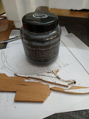
The pieces at various angles to the grain and joined by “black” glue (PVA+charcoal) - the contrast looks better this way.
Dry fit to the curve of the stem, with adjustments as necessary- a few light touches with the spindle sander was effective.
Bobstay holes and gammoning slot as shown, with milling piece #56
The combined piece needs tapering -from 5.3 to 2.12 mm at top of bobstay piece- the top of lacing pieces only to 3.18mm.That is from below, above and aft, forward .
As before, I did this by cutting a pattern of this taper and sticking this to the fore curve.
Tapering by alternate sanding on stati sanding board.
A small imperfection in the wood was noted on the bobstay piece but I expected that this would be removed with the taper. Instead it grew like some cancerous iceberg.No camouflaging this.
(Of course the piece with the extra work-holes and slot)
Remove and, of course, the cutwater was damaged, and this also had to be remade.
Another lesson I must remember- don’t waste time on suspect material.
When satisfied with taper, glue felt for joint to stem.
More mistakes- didn’t allow for thickness of felt and didn’t notice thoat snug fit caused the the gripe to lift away.
Reset and the felt removed , some sanding to allow for felt in joint.And reattached.
Glue reinforced with wooden trunnels from aft aspect of stem. These are limited because the thin drill bits are short.
Augmented adhesion with rubber band and S@@$%T- all slipped off, taking gripe with it.
Again clean all up (paper and glue is messy) and try again- this time with copper wire trunnels from front and back- and finger pressure. Ensure alignment with string midline from top of building slip supports for and aft.
? How to improve bond when using the intervening paper- wood is not being glued directly to wood.
While setting, made the last 2 upper pieces- standard and extension pieces.
These are thinner , 3.71 tapering to 3.18 (matching top of lacingpiece). Added the hole (larger, use #52) and the aft gammoning slit.
Fitted them separately, but perhaps would have been easier to glue together before final shaping.
Used coloured glue for joint-not sure if this was ok join to stem, but sick of using the black paper.
Difficult to clean up-was frightened of breaking it off.

61.jpg-61.jpg61f.jpg61b.jpg61h.jpg
 
Need help/advice

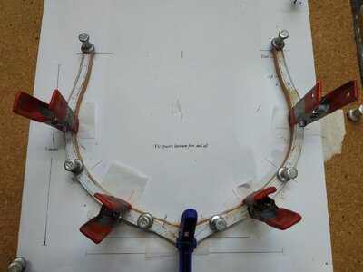
Now making the the square frames as suggested -reducing size pats/futtocks-10",9.5" and 9".

I tapered the transition points and ended with timber tops too thin or wave profile.

Should the transition points -chock or scarf- be left as step?

What have I forgotten or not understood?
 
Square frames.

If not the heart and soul, then the “body” of the fully framed ship.
The drawings become simple when understood!
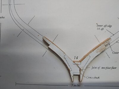
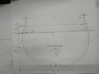
Each pattern shares a pair of frames- one side represents the fore and the other, the aft. The secret is to keep these separate by overdrawing so as not to get lost.
Remembering that at amidships, the direction is reversed.
Starting with aft set- the aft one of the pair is “floored”- the joint above the keel.
The fore has a chock (separating the two wings) that sits on the keel.
This may be obvious to some but I needed a mental effort to implant this in my brain.
Cut out card pattern to see if fits to aft cants-OK
It is suggested that the futtocks can be graded in width: 5.3mm,5.04mmand 4.77mm -instead of all one size.
The 14 aft is relatively thin so I decided for this one to make a scarf joint rather than a chock.
I don’t know if mixing was “allowed”-but it's my model!
Made the first like this (14 aft) and made the mistake of tapering to blend the joint widths- ended up with too thin a timbertop.
Asked advice on forum (thank you) and tried the step method-step is only 0.13mm either side.
Next attempt-forgot my intentions and layed out all parts on the 5.3 blank!
Used milling to reduce and realised that difference to my eye was minimal
.Checked my framing plan (rather blurred) -the frames vary in width side to side but barely noticeable between futtocks.
I’m sticking to uniformity- that is the 5.3 blanks.
Stick the cutouts to another copy of the plan, with generous extra width to allow matching with the neighbouring aft cant.
Clamp (watch for slippage) and attach a stabilizing bar across top and mark its centre point.
Reference is made to a Greek letter designating the wood to be removed where the bridge of the 2 halves of the frame sit on the sling deadwood. I was lost, so I used a coarse file angled by eye and by trial and error made a rough fit so it could sit at a right angle to the board, and parallel to the cants.
The angle of the feet where it sits on the curved bearding line is sanded- but feet left long for present.
The height that frame sits is determined by the height of 2nd futtock head.
This has to be plotted, as it is not shown on the plans. TFFM explains how -in straightforward fashion, transferring points from aft body plan to the sheer plan. This is compared to actual height. Mine comes out at measured 9.35mm.
Perhaps by good luck, #14 needs no further attention and can be glued into place, using the upright board of the building slip to check alignment and hold in place.
#14 fore:
The partner with a chock (shaped like short-handled pliers) forming a base between a pair of “wings” each with lower and upper futtocks(1 and2).
As these parts are thicker, I used chocks instead of scarf joints.
The space between the aft and fore frames measures approx. 3.15 mm on my framing plan. Small spacer laid on deadwood to site the fore piece.
The “seat” on the deadwood was fashioned as before, the feet trimmed, and spacers glued to top of futtocks.
The piece glued to the deadwood with the “dry”spacer temporarily left in place.
The last picture is a new measure/marker-very useful71a.jpg71c.jpg1121a.jpg1121b.jpg1121.jpg
 
I’m surprised you are able to keep your frames aligned without a building jig to support them. Your explanation is very detailed. Thanks for posting.
I use the "professional building slip" It stabilizes stem, stern and keel. The small bits separating the tops of the futtocks help, but cants still unstable. I hope that the square frames with their better seating, will stabilize further. For this reason I delayed fairing of lower cants until later. A building jig makes life easier (either upright or Hahn style) but I would need cleverer people than me to provide such a plan a plan.
 
#13 square frames.
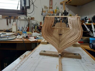
Similar to #14 but with a narrower gap with separation pieces at right angles between the ribs.
The gap is 2.3mm, the pieces 3.71wide. The are set above (3.71) and below(4.7)joint line,with an extra one further up the 2 futtock at14.4mm
After filing the angle and depth of the “seat”, checking the height of the futtock head against the line previously drawn on the sheer plan.
The separation pieces were glued to the (fore aspect) of aft rib, whose seat was then glued to the deadwood.
Remember that the fore piece has the extra height -timberhead.
The chocks are made with a large “tail” for ease of handling. (later removed by spindle sander before fixing the rib to its place.
Filing seat, checking height and symmetry-The front of the seat just covers the end of the deadwood step.
Small dabs of glue on spacers (extra one at level of deadwood NOT glued to either side).
Several clamps on each side of the pair of ribs to ensure good fit.
Looks good- very satisfyingView attachment 206590View attachment 206591View attachment 2065921721a.jpg1721b.jpg1721d.jpg
 
#12 square frame
The aft one of the pair is again “cast forward”by 1.06mm-a dogleg that will form an upright for a port.
This means that the upper futtock an extra 1.06mm thick.-total 6.36mm.
The frame also has a timberhead.
Make note of height of sill as the cast must end below this.(11.3cm)
Again postponed making the sill mortise-although easier off model, measurement is too critical.
I started the shift 10mm above the futtock head.The mill was used to remove the necessary wood and a transition slope ,sanded.
Before fixing in place,a critical problem (for me at least) needed to be solved.
The position of frames #12 and #11 are determined by the width of the port opening-the fore #11 forms the second port frame.
This is given in TFFM as 15.1mm-This will mean the frames will need to be somewhat crowded- the usual spacing not working.
My framing pattern does show use of narrower timbers, and less gaps, but also a port opening of 16.3mm. The other ports are however 15.1mm, so I decided for symmetry and same thickness timbers. Fore #12 and aft #11 will be short, supporting the sill, and a narrow gap between them.
Additionally, the #11 pair are again separated by spacers.
Here I found another problem. The rising wood finishes between the pair.I assumed a faint vertical line marked the spot on my sheer pattern.This appears to be too short.
There is a difference in width and I decided to simply narrow the notch of the aft frame.
(If this leads to a problem later on please let me know.)
Also, to ensure my measuring of port gap was correct, I glued together the #11 pair with their spacers, off the model, and then confirmed my estimate and only then, glued the pair to their seats on the keel.2121.jpg2121a.jpg2121b.jpg
 
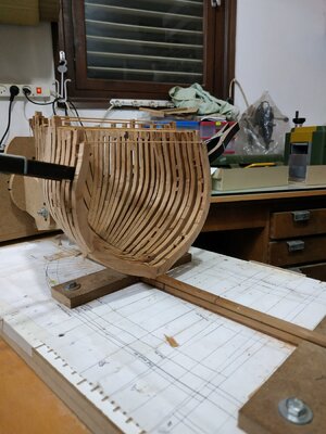
Fairing:
Should be straight forward, using a cutout of the foremost frame as a guide.
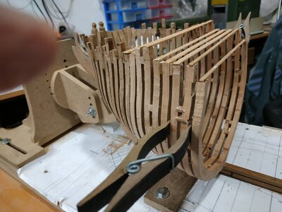
Extra strength with the cross spells and a supporting hand did not prevent a complete break through a couple chocks.
Where possible, as a contrast, the chocks were cut cross grain. These were a point of weakness and a mistake. Of course I have been heavy handed with the 80 or 100 sandpaper.
I had to remove the squares and remake the chocks.
Also the spacers at the top of the futtocks kept separating- should have reinforced with trunnels.
When building from scratch, there is much to think about. Even with the wonderful TFFM, something , even basics, is forgotten.
I’m often learning something new, but forgetting something old-is this intellectual equilibrium or senility?

271.jpg

271a.jpg
 
Last edited by a moderator:
My dear friend
The best memory is made in the systematic and professional work, as can be proved from your professional and beautiful construction methods. Well done, I have no doubt the model came out excellent
 
#L-fore square frame
Moving to the front of the ship, the FLOOR is now FORE and the aft has the chock.
This fore has a forward facing dog leg.
The gap between its companion is for a sill-thus 15.11mm.
Firstly, as for aft frames,plot 2nd futtock height on the sheer plan.#L=9.2mm.
This fore part also has the timberhead.
Lookin at my framing plan, it seems that the start of the dog leg is lower -as are the others not yet built.
The card pattern seemed OK but when I made the actual piece, there was a misalignment with the fore cants. Rechecking, these seemed to be 1 or 2 mm out.I think that when the spacers separated when fairing, I stuck them back as individuals to its neighbour without checking the whole run.
With a mdf profile, I unglued and re-stuck in the corrected position.
It is important to ensure that the angle of the cants remains at 90deg vertical while following the angle to the keel. Some of mine needed improvement -I altered the thickness of some of the spacers as required.
The inner aspect of the #L was now slightly too narrow, so I remade it with more spare than usual.
Allowance for angle of cant means that the seat of #L is less than the 15.1mm distance of the sill .Used a sizing block.

#K frame
Referred to as a frame bend- separated by a number of spacers- as #13-above and below the joint lines.
The fore of the pair has the timberhead.
The aft sits on a wider part of the keel and needs to be adapted as not shown on the plan.
The “legs” astride the keel are shorter so for extra stability I put a slightly thicker (0.8mm) bamboo trunnel at this stage.
The futtock head height is 8.9mm as I measured it.
12.jpg271.jpg12c.jpg12a.jpg
 
# J square frames.
Reviewing Kevin Kenny’s video, using the 5 min. Epoxy for its greater strength, non-adhesive clear paper (greaseproof) to reduce mess and pining the parts to the board through the wood, for fixation while assembling and drying.
I’ve had issues with movement and breakages despite trying to ensure a good fit at the joints.
Can I blame the weather ?- from winter to spring and back again every few days-10c+rain then 25c+.
#H and #J are “connected” so may assemble off keel first.
#J- no timberheads.
2nd futtock height 8.7mm
There are mortises on aft aspect of aft rib of the pair-for the sweep port sills.
The given measurements in TFFM (scale metric) -2mm thick sills forming a port of 4.24mm square.
My framing plans have blurred lines, but these ports look rectangular.
Until now have postponed making these mortises, having tried and failed on practice pieces.
To make this after attaching the frames looked even more difficult.
I milled the mortise calculating the height of the lower edge from the sheer plan-10.4mm from base. Although square, I think I can fake the “angle” appearance later.
I don’t know if intentional, but the 5in horizontal line on frame plan is the same distance from the seat as my keel is high (0.95mm)
Therefore by putting the frame on its plan, it was easily marked.
# H
Another bend pair - spacers separating the pair as before.
The fore aspect has the matching mortises for the sweep ports.
The aft aspect of same frame has a mortise for a port-starting at same height but allowing for sill of thickness of 2.65mm (marked by placing on #J frame plan)
The height of the port is 14.1mm with an upper mortise of 6.3mm.
Assembling these frames on the keel, the frames are too aft on the keel.
Revised my decision, and recut sills to form a sweep port width of 3.5mm (equivalent to 6.6in not the 8in)
The aft of #H is still 2mm aft of its line. Need to compensate,
The picture is pre-fairing and shows excessive “spare”
The bird is an Egyptian42e.jpg42d.jpg42c.jpg42b.jpg42a.jpg42.jpg Goose and chicks seen on walk at local pond yesterday.
 
Back
Top