-

Win a Free Custom Engraved Brass Coin!!!
As a way to introduce our brass coins to the community, we will raffle off a free coin during the month of August. Follow link ABOVE for instructions for entering.
-

PRE-ORDER SHIPS IN SCALE TODAY!
The beloved Ships in Scale Magazine is back and charting a new course for 2026!
Discover new skills, new techniques, and new inspirations in every issue.
NOTE THAT OUR FIRST ISSUE WILL BE JAN/FEB 2026
You are using an out of date browser. It may not display this or other websites correctly.
You should upgrade or use an alternative browser.
You should upgrade or use an alternative browser.
? Are you serious.
As a senior citizen of the UK, I thought that this expression was an americanism from the 50's movies.
I "woke" up to this distressing news. What will happen to the likes of Chick Chorea ? Maybe this sensitivity caused the impersonation by Danny Kaye when wanting to order eggs?
In truth I wanted to use the word gosling, but my wife suggested otherwise -obviously to cause this embarrassment.
I am watching the series Mrs America at present - maybe a subconscious need to agree with my wife . ( I have a CONCIOUS fear to disagree.)
It is one of the 'urban' dictionary definitions...not mine 
By the way, young woman were referred to as "bints" in 40's and 50's (Arabic/soldiers returning from middle east service) and "birds" in my youth (1960's). A "dolly bird" was very complimentary-It is one of the 'urban' dictionary definitions...not mine
This is now probably thought of as "objectifying", but has nature, especially a young man's, really changed? Is beauty still allowed in the eye of the beholder?
(Hope this is not too serious)
Then we get older and wiser and call them bit...oh crap here comes the Admiral, delete delete delete...
#G
Fore of pair -scarph joint-will be shortened to be under the port.
Aft-with toptimber-also shifted forward and with motises for sill foreward and mortises for sweep ports aft.
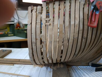
Not worked on ship for a couple of days and when rechecking height of sills, some discrepancy between port and starboard is noted. Frames J and H tilted and reset
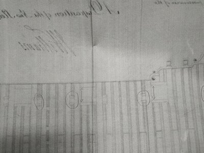
Further confusion. On my (not so clear) framing plan, there seems to be a variation in size of ports (by height) and the sweep ports do not measure as square-3.5mmwide and 4.2 high.
CAN SOMEONE PLEASE HELP AND CLARIFY THIS.
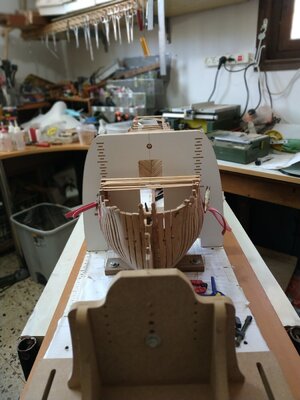

Maybe a (or some) photos of the drawings are making it more clear, where you (or the drawings) have the problem. The attached photo is not helping (for me in the moment) to understand#G
Fore of pair -scarph joint-will be shortened to be under the port.
Aft-with toptimber-also shifted foreward and with motises for sill foreward and mortises for sweep ports aft.
Not worked on ship for a couple of days and when rechecking height of sills, some discrepancy between port and starboard is noted. Frames J and H tilted and reset
Further confusion. On my (not so clear) framing plan, there seems to be a variation in size of ports (by height) and the sweep ports do not measure as square-3.5mmwide and 4.2 high.
CAN SOMEONE PLEASE HELP AND CLARIFY THIS.
Thanks for you interest.
The sweep ports as shown appear rectangular, not square. Is this possible or likely?
If only square acceptable, I have 2 options:-
I. the 8ins as mentioned in TFFM
2. smaller i.e. my width squared.
The problem with the 8 ins. means spacing between other frames will be narrowed significantly.
The other "varient" is the difference in height of port openings- while the width seems similar-? artifact or real.

- Joined
- Nov 10, 2020
- Messages
- 257
- Points
- 323

Hi Stuart,
Just saw your log over here on SOS.
IMO - keep your ports square as you can, the drawings have some “ instability” in them, and you have to “notch” into or “shift/cast” the frames around them to get them right.sweep port lower cills follow the curve line of the lower cills for the gun ports.
just make sure all ports are the same height, length and position port/starboard or your model will look oddly offset.
sorry I have not been much help to you, I have not been spending much time modeling in the past year, I will try and be around more in the future.
Thank youHi Stuart,
Just saw your log over here on SOS.
IMO - keep your ports square as you can, the drawings have some “ instability” in them, and you have to “notch” into or “shift/cast” the frames around them to get them right.sweep port lower cills follow the curve line of the lower cills for the gun ports.
just make sure all ports are the same height, length and position port/starboard or your model will look oddly offset.
sorry I have not been much help to you, I have not been spending much time modeling in the past year, I will try and be around more in the future.
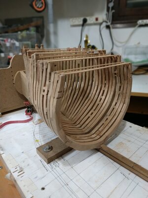
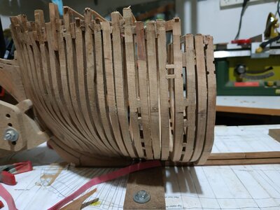
Fairing frames #G to #L
I’m having more trouble with these than the numbered aft frames.
Is it my DYSLEXIA?
With the frames viewed as a group, it is obvious that J fore too thin-removed and remade.
The group still looks mal-aligned after some initial sanding. It appears that the depth of the seating notch are not accurate enough , so the curves are out.
Decided to remove all, as the problem seems to start with #L. Fortunately they are glued to the keel with PVA -alcohol does the job.
Each frame rechecked against the plans
Remake #k and #L (it was mistakenly misplaced with #H and overly faired)
Second futtock and port heights double checked.
Fairing inside is difficult and the curves require various techniques, and less opportunity to use electrical tools.
Reduced tendency for upper spacers to separate by using a cut rubber band to brace them.
I am leaving final faring and finish until all frames are in place.
*** Unhappy with the appearance of frames fore and aft of the sweep port. The distance between #J and #H is 4.24mm. This means the space between the pair of J’s is narrowed to 1.5mm.The space after is fixed as it is a bend pair. It looks weird.
I’m thinking of making #J aft with a forward shift.
Opinions and advice please.
( Just noticed #G aft is seated 1.5mm too high)
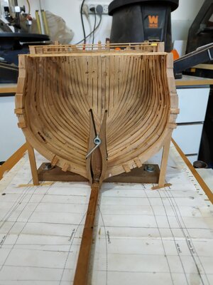
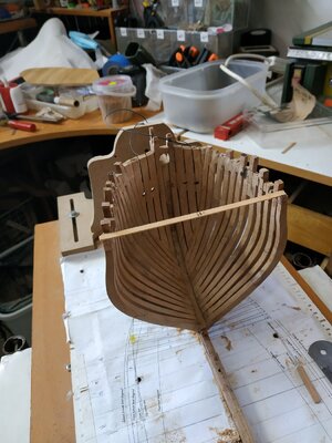
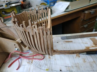
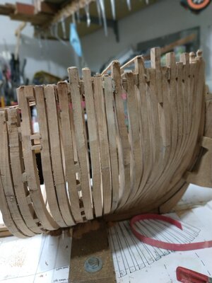


Last edited by a moderator:
- Joined
- Nov 10, 2020
- Messages
- 257
- Points
- 323

Hi
if it looks wrong, it proberbly is.
Remeasure again from the plans of the ship you are building.
The space between frames by the keel should be very close, the space at the top timber’s will vary due to casting and shifting as we discussed for port framing.
If I had to do it again, I would frame everything first and then measure and cut the ports like Greg did - way more accurate.
ben
Too true. Tried to minimise by using cut bands held by clamp.Oh, and watch out using rubber bands to hold frames in place, they can also pull the frames in funny positions if they are not perfectly straight and not too tight.
Also, without (unmarked)shifting, how can be frames be close and accommodate the 8in square sweep ports!
You are correct about the accuracy of ports, but I find easy to mill the mortise before fitting-maybe compromise and make a narrow "guide" and expand when fully framed.
Thanks again for advise ( Perhaps some warning BEFORE next stage mistakes)
Keep warm and well
Square frames #10to-#6
#10-straightforward
Just remember that floor is aft and maintain position to the horizontal line as marked on the breadth plan.
#9-spacers and fore with timberhead
As these are “simpler” I made them with less “spare” and used as a more accurate guide to fairing.
Double check that the frames are “vertical”-90deg to the building board.
#8- Aft with timberhead and forward shift.
Forgot to mill mortises and only noticed after fitting the next set of frames- maybe for the best and decide to leave to later.
#7 - a bend pair (with spacers)
The frame spacing on the breadth plan and framing plan needs to accommodate this spacing as well as the port gap between aft#8 and fore#7.
I narrow spacers to 2mm
Again, spacing on keel needs reassessing with each placement.
Some delay since last post -work and family restrict building time-conflict of priorities!!
I post a picture of a younger member of the family- dressed up as “Woody”
From Toy Story. The name justifies the connection to the hobby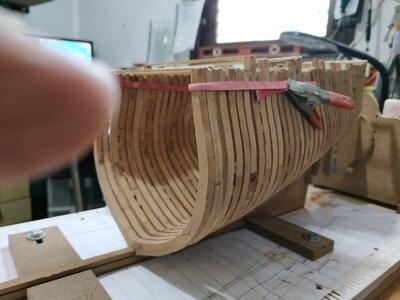
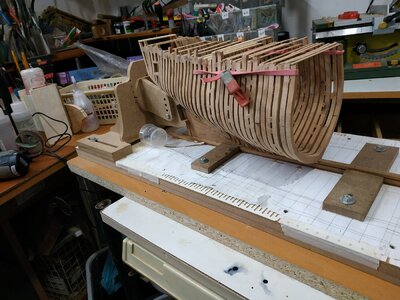

#10-straightforward
Just remember that floor is aft and maintain position to the horizontal line as marked on the breadth plan.
#9-spacers and fore with timberhead
As these are “simpler” I made them with less “spare” and used as a more accurate guide to fairing.
Double check that the frames are “vertical”-90deg to the building board.
#8- Aft with timberhead and forward shift.
Forgot to mill mortises and only noticed after fitting the next set of frames- maybe for the best and decide to leave to later.
#7 - a bend pair (with spacers)
The frame spacing on the breadth plan and framing plan needs to accommodate this spacing as well as the port gap between aft#8 and fore#7.
I narrow spacers to 2mm
- Perhaps if I had made the frames with diminishing thickness, this would be less of a problem. (If and when I repeat this build, this is what I will do)
Again, spacing on keel needs reassessing with each placement.
Some delay since last post -work and family restrict building time-conflict of priorities!!
I post a picture of a younger member of the family- dressed up as “Woody”
From Toy Story. The name justifies the connection to the hobby


Last edited:
Return to lettered frames.
#F- my framing plan seems to show a thinned fore face of the fore upper futtock to allow for sweep port.
Decided again to postpone mortesses until framing completed to avoid height issues.( Although using the mill before fitting, mistakes may necessitate remaking frame.
#E- no shift mentioned, but will need one aft to accommodate another sweep port.
#D- In order to allow sweep port foreward and gun port aft ,fore D is straight ie without shift, a wider 3mm space needed between seats of #E aft and #D foreward.
#D is also a bend pair-spacers required.
#C-aft has forward shift for port . The distance between these frame determined by port width and therefore between #Cfore and #Daft, only 1mm.Between #C’s, 2mm
NOTICED MAJOR ERROR. The earlier shifts were cast i.e.dog leg. This was employed incorrectly on some frames such as #G. I think I can correct this with a file while frame attached- I don’t particularly want to remove and rebuild.
#B- spacers On framing plan, more and different pattern, but same plan doesn’t show anything special either side of the central #0, which is clear on individual frame plans of TFFM. Will therefore continue pairs of spacers as before.
Return to numbered frames.
ANOTHER MISTAKE.
My reference mark on frame/plan is now obscured, and some movement seems to have occurred. Premarking frame placing is difficult as this is determined as the build develops.
Using the aft point of keel and joints near the stem, gives some discrepancy. I can’t understand why. I've checked multiple times. Difficult to blame expansion or contraction of wood.
The difference is only couple of mm, but I will have to treat the remaining frames as a group, so as to maintain consistent gaps while maintaining rules for port widths.
#5- Aft timberhead. Fore foreward shift ? to avoid too large a gap when the aft#4 also shifts.
#4- aft has a foreward cast (dogleg) . I now remember the difference.
Fore- simple
#3 Bend pair- spacers
#2 Aft shifted forward.for sweep port
I’ve mentioned problems with spacing to allow for these sweep ports. In truth, lost sleep over this. Caught up with Kevin’s video, where he mentions thousand confirms the solution I had been toying with only as I was unsure if “acceptable”.He points out the plan actually show the opening into the frame itself one one side. Now I can SEE the solution for myself once my attention is drawn to it.
(How often in life is something obvious once it has been highlighted- in medicine we often see cases after a certain syndrome or sign is reported , as if it previously didn’t exist)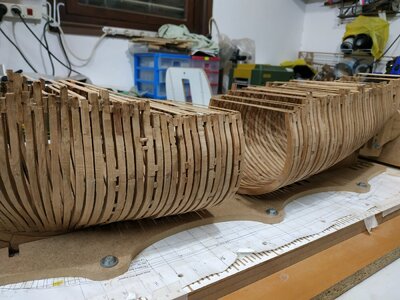
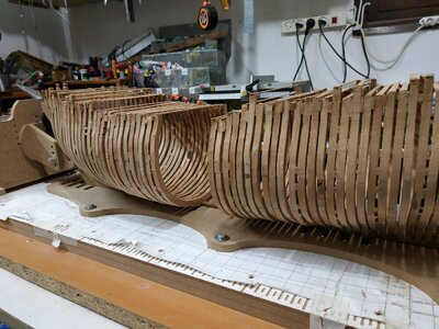
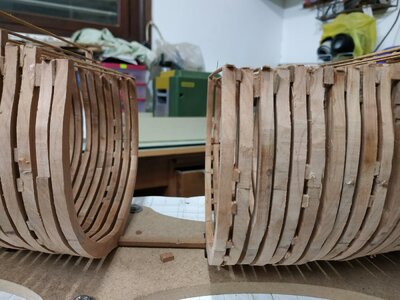


#B
A pair of bend frames, but they are shown on framing plan with a larger number of spacers (but the but where this should happen is not so marked) I assume this is a mistake. Spacing foreward must allow for a sweep port.
The narrowing gap between this pair and #2 is important so as to allow remaining frames to be placed with appropriate spacing.
Measured and calculated several times, the gap on the keel seems barely to be enough
.
#A fore-regular
Aft a shift forward which at its upper futtock, widens to close gap to neighbouring fore#1.
This is to accommodate a pulley block above the sweep port (to be inserted later). I used a wider (7.3mm)blank and milled the aft part for the shift and lower fore part so the upper part remaining closed the gap to the next frame.
# The remaining frames :
Some confusion with the order/numbering.
With various hints and referral to the framing plan, it seems the order is (going forward) :-
Pair #1 (bend), #1B, #1A, #1O,#O (center) #AO, #A1
#1B - shift aftward and sweep port recessed more so gap to next frame is narrower than usual
# O- thinner frame -4.77mm-and each joint is framed by spacers on either side (also narrower than usual). The frame plans suggest fixing the first to the frames fore and aft (#O1 and #OA) but I felt easier to match by fixing the to both sides of #O.
Note these three all have cross chocks as bases.
Spaces between these frames are also narrower and as I seemed to be running out of space on the keel, made them at 1.60mm.
Nevertheless, when I dry fitted the last few frames I lacked 4mm. Not much, but the crowding was unacceptable.
One cause was the extra width allowed for the sweep ports until I learned that they were “countersunk” or recessed.
Anyway, some of the frames were not very good and I’d already made some other gaps too narrow.
Most of the problems were among the lettered frames ( that dyslexia again).
I removed most of the frames (alcohol) and remade completely 3 (#J,#H,#F)
Changed the casts to shifts where I had earlier made mistakes.
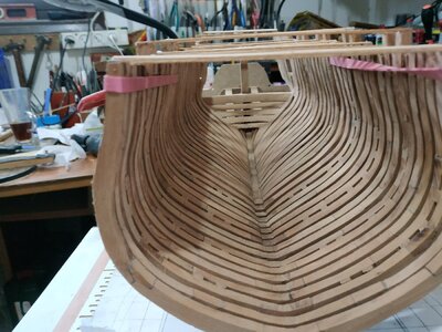
After a couple of days of remedial modelling, all fit with the appropriate spacing.
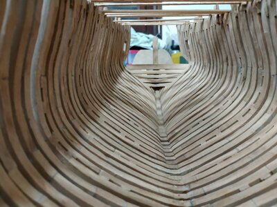
8 months of work -frustrating and satisfying- much progress in understanding and craft, but a landmark. Still to make ports, fairing etc and still on ch 3 vol 1 (of 3), but a landmark nevertheless.
IF I CAN DO IT, SO CAN YOU!!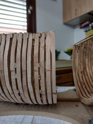
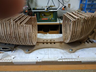
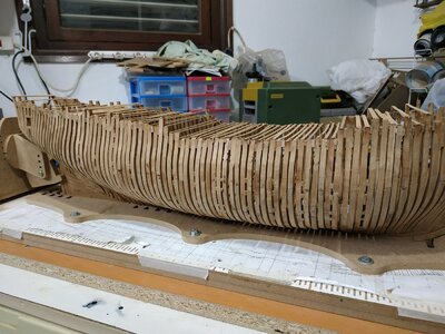
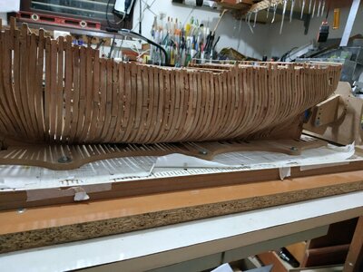


Congratulation for reaching this important step..... you will see, that after sanding you will love her body !!
BTW: often the glue is producing additional micrometers and with the number of joints also some milimeters......good that you have solved the problem of your 4mm
BTW: often the glue is producing additional micrometers and with the number of joints also some milimeters......good that you have solved the problem of your 4mm


