Tecumseth 1815

there are not too many skylights you can observe up close out in the wild. They are one of the first structures to fall apart.

sometimes you do get a glimpse

skylite2.jpgnewspaper photo.jpgwreck1.jpgwreck2.jpg
 
so here we go

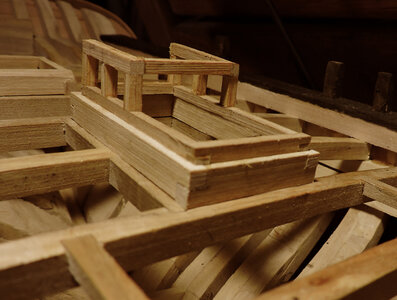
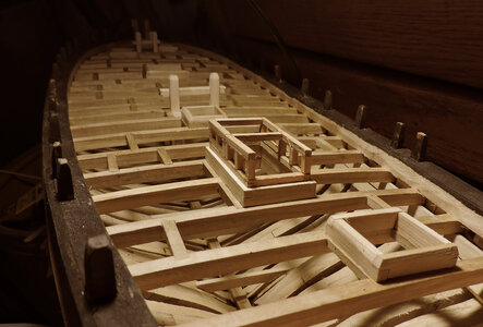
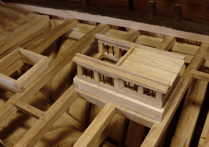
i started with a sill on top of the coaming, the corners of the sill lapped just like the coamings

cw1.jpg
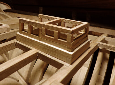
with the sill in place the sides are built on the sill, the vertical posts would have been mortised into the sill.

cw2.jpg

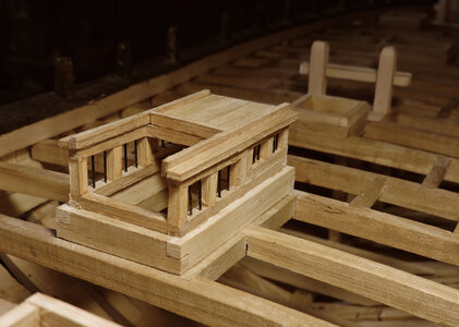
The construction is simple with a sill, vertical posts and a header.

cw3.jpgcw4.jpg

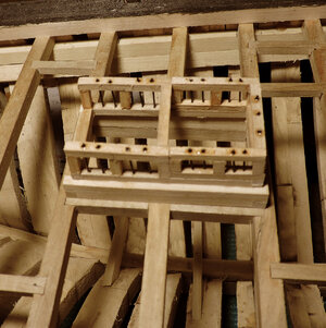
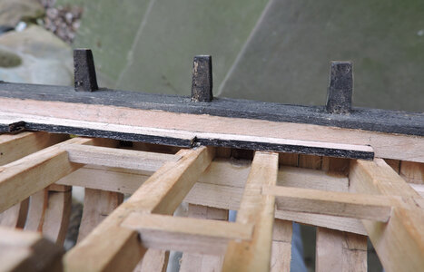
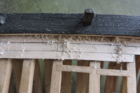
once the framing is complete i drilled holes through the header and down into the sill. Using plastic rods i painted them black and ran them through the drilled holes. Once the rods are in place a dab of glue was used to hold them in place. Before the roof planks were installed the header was given a light sanding to smooth out the bumps from the ends of the rods and glue.


cw5.jpg

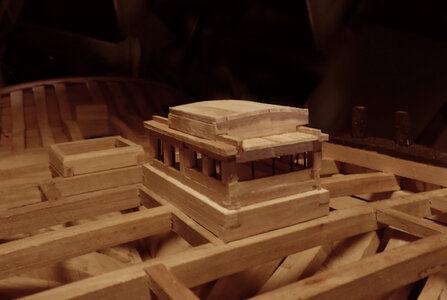
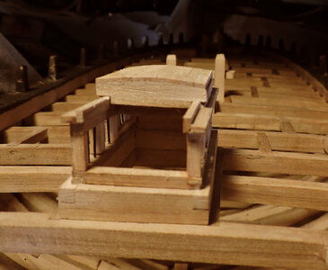
the roof planks were simple just cut to length and glued in place

cw6.jpgcw7.jpg

the last piece of the companionway is the sliding cover.

cw8.jpgcw9.jpg

this completes the deck structures so next is to put down some deck planking.
 
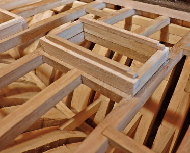
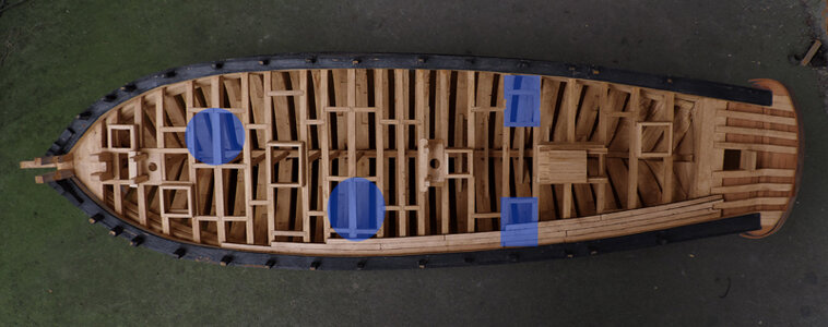
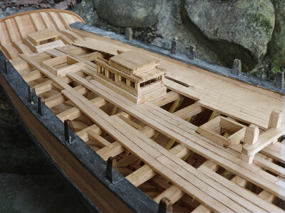
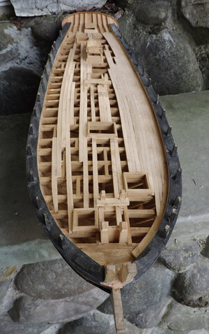
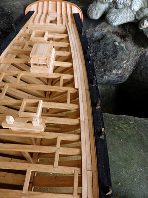
starting on the decking i want to get enough deck planks on so i can mount the guns in the blue areas. Leaving open areas to show some deck beams and carlings.

deck1.jpg

Material i am using for the decking is Maple because it is not that stark white like Holly and when finished is a honey color which will be close to the Pine color of an actual deck.

deck2.jpg

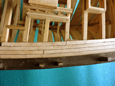
As for the caulking i tested a few ideas like eye liner from the cosmetic shelf that worked pretty well but it was slightly too soft, then i tried magic marker and that had a tendency to bleed and gave a fuzzy edge, Heavy body acrylic paint was just too messy and got on the surface of the planks, graphite pencil was to light and then i tried a China Marker and that was perfect, also pastel artist crayons worked good. Both these will get on the surface but it will easy scrape off giving a clean sharp caulk line. The picture is the China Marker before i scraped the deck clean.

deck3.jpg
 
Last edited:
planning out the decking the first thing to look at is the shape of the deck.
If i ran the planks straight when i get to the sides the ends of the planks all end in a point

deck8.jpg


if i follow the shape of the deck there are no pointed planks to contend with.

deck4.jpg

the question is do decks actually follow the shape of the hull or do they run straight? from a number of examples i found the answer is both. It might depend on the shape of the hull or it might be a matter of how the master shipwright decided how to lay the deck. In most cases i found the deck planks bend.

deck10.jpg


but the planks only bend from midship to the stern, from midship to the bow the planks are straight

deck9.jpg

from a constructional point of view bending the deck planks would be a better way to lay a deck and avoid the run of planking ending at a point.

The question is it possible to bend planks edgewise? i found when using scale planks it is quite easy. Deck planks on models are not to the correct scale so it might be more difficult to bend them. Actual deck planks are more like a beam and almost as thick as they are wide as apposed to planking on a model where the planks are much thinner than what the should be.

planksc2.jpgplanksc1.jpg
deck4.jpg
 
As for the caulking i am using a China Marker which is a soft wax crayon that is slightly sticky. I coated the sides of each plank.

deck5.jpg

when the planks are put down, they look a little messy and some flakes will get on the surface of the planks.

deck6.jpg

once you scrape the deck the planks clean up very nice and leave a clean caulk line.

deck7.jpg
 
back a few years i built the Alvin Clark and wanted to show more construction of the ship so i used a minimum amount of planking.

Deck1.jpg

here you can see the same style of building on the Halifax


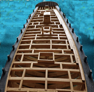
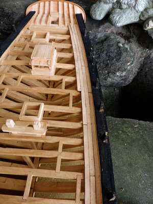
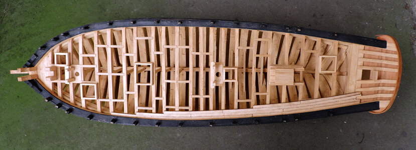
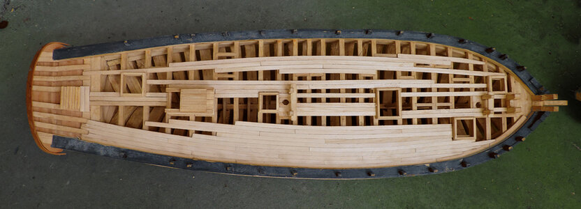
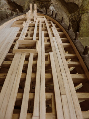
i decided to use the same approach on the Tecumseth leaving areas open to expose the construction of the hull.


Deck2.jpg

deck4.jpg

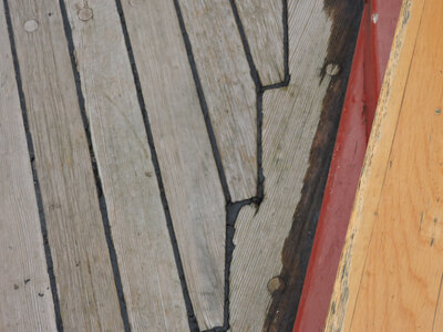
i did include areas of interest like the nibbing of the ends of planks

deck5.jpg

deck7.jpg
 
Last edited:
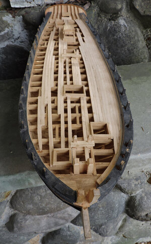
i did plank a section that will go under one of the guns to the right. also i wanted to show the curving of the deck planks
deck6.jpg

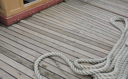
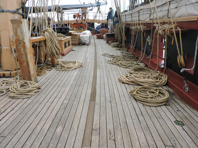
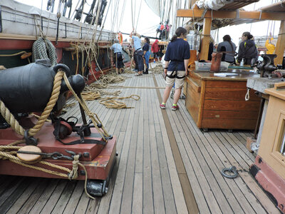
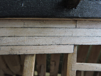
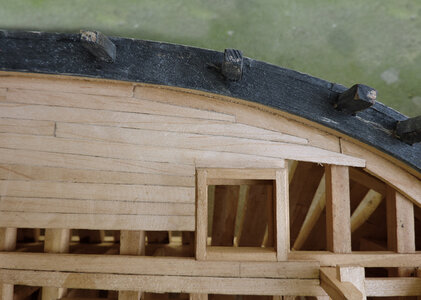
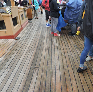
Just about all the models you see have a straight run of deck planks. In the case of the Tecumseth the deck planks run on a curve to match the shape of the hull. When you talk to model ship builders about bending planks edgewise they will tell you it is difficult because planks tend to buckle. In some cases deck planks are not what you get in a kit, In kits the planks are thin and wide which indeed makes them difficult to bend edgewise. In reality deck planks are not thin wide "planks" they are almost as thick as they are wide making them more like a beam and not a plank.
Notice peoples shoes they are as long as 3 planks so if the average shoe of an adult is from 10 to 12 inches divide that by 3 a plank is from 3 1/2 to 4 inches and the thickness of decks are 2 1/2 to 3 inches. This makes them easy to bend.
deck9.jpg

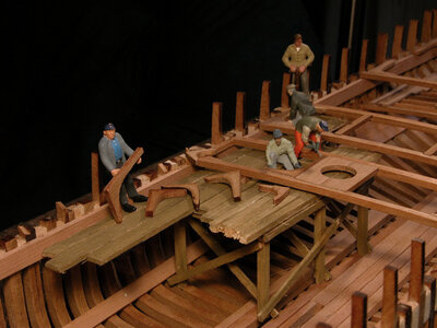
another thing to consider is the tear drop shape of the hull there is no section that is close to being straight like the Alvin Clark. This means either all the planks for and aft will end in a point or they have to be nibbed into a margin plank.

Deck1.jpg

The study of the Tecumseth and Newash states there was no indication of deck knees used. In ship building lodging knees were installed along the side of the hull.
knees.jpg


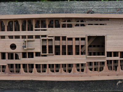
What this does is to give a solid band of wood along the side of the deck.
deck.jpg

in the case of the Tecumseth there is no structural support along the side, it is hollow. deck beams are set between the deck clamp below and the waterway above. If you were to run the deck planking straight odds of the nibbed end of every plank landing on a beam is slim, so you end up with the ends floating in air with no support. running planking curved along the side of the ship eliminates this problem.
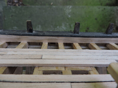

deck3.jpg

At some point in laying the deck you do have to compensate for the curve and adjust the planks to fit. Down the center of the deck you have a number of things to work around like hatches, posts, companionways etc. so you have to cut and fit planks might as well make the curve adjustments in this area. Here are some ways this was done.

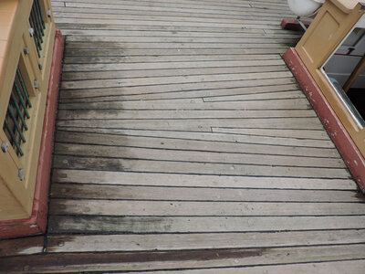
deck10.jpgdeck11.jpgDeck13.jpgDeck14.jpgDeck15.jpg

This ends the planking of the deck and now moving on to the guns
deck8.jpg
 
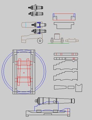
to get started on the Tecumseth guns i need a plan so i drew one up.
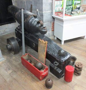
as for the wheels on the carronade well it could go either way iron or wood. My feeling it could be like the pictures because the guns might of been taken from what was in storage at Kingston. So if the carronade was sent to the Tecumseth might as well send the whole thing.
These 2 carronades were big guns and sat on nothing more than a big timber. The 24 pound cannons were mounted on a sled and iron ring.
personally i like the iron wheels because it is a different touch to what is commonly seen on models. But i do have 1/2 wheels on hand so that is much easier than having to 3D model the wheels and find someone to print them.

by the way that is not me in the picture i don't know who he is

guns.JPG

1808_24-pounder.jpgkingston32-pounder-carronade.jpg
 
Last edited:
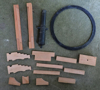
i finished the parts for the sled and carriage for the 24 pound cannon. The hole in the center of the sled part is for a pin that runs through the sled and deck beam.

gun1.jpg

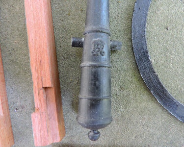
detailed the cannon with the crown

gun2.jpg

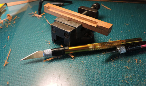
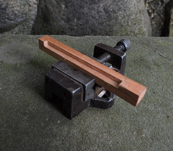
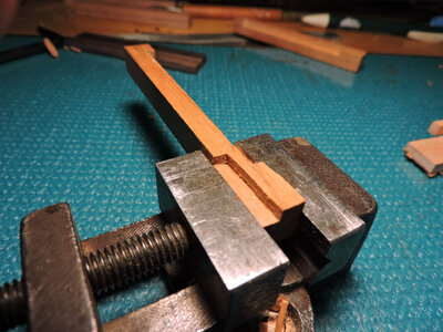
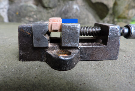
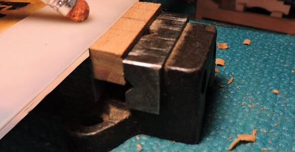
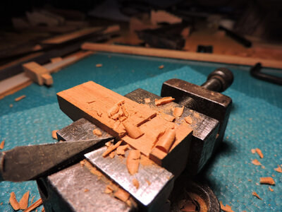
making the groves in the sled was easy and done with just an Exacto blade and vice

gun3.jpggun4.jpg

same with the inset for the brace

gun5.jpg
 
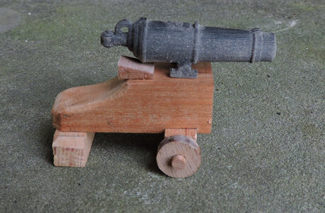
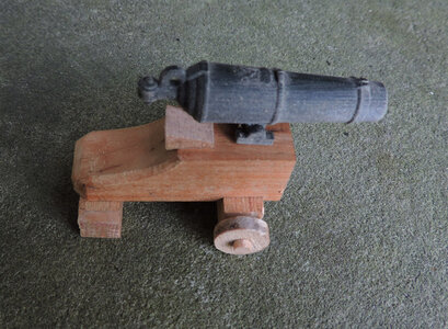
the other set of guns on the Tecumseth were 2 carronades set up to fire over the rail.

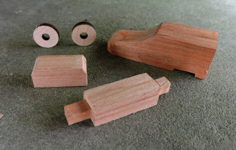
first is to make the parts which are just a heavy timber, axel, wheels and a block

gun14.jpg

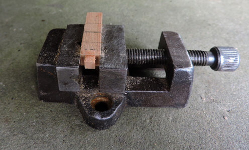
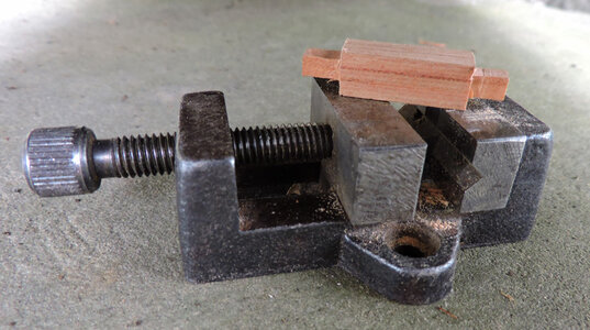
making the axel was done in a vice

gun15.jpg

i took a piece of plastic the correct height and set the axel level with the top of the plastic then cut it down to the face of the vice, turned the axel and did the same on 4 sides

gun16.jpg

gun18.jpg

gun17.jpg

cutting a notch for the axel was done in a vice and a knife

gun19.jpg

assembled

gun20.jpggun21.jpg
 
before i mount the rings, sleds and 24 pound cannons and the carronades there is one other job to do. That is the install the railing, a job i am not looking forward in doing. To install the railing means first i have to redo the stern. The stern was a struggle to begin with now i have to rip it apart, come up with a different design and rebuild.
 
Back
Top