Tecumseth 1815

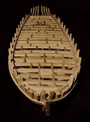
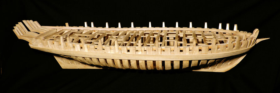
the Tecumseth project reached a mile stone and all the timbering is done. It is like building a house where all the structural framing is finished and now it is time to move on to the next phase of building.

I can stop here because my goal was to reconstruct the Tecumseth which is now done what is left is planking and joinery work.
 
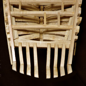
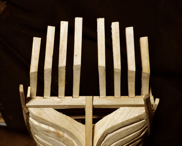
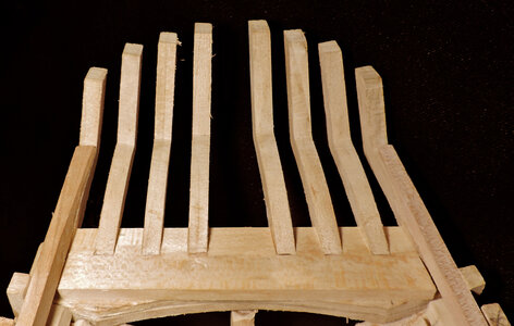
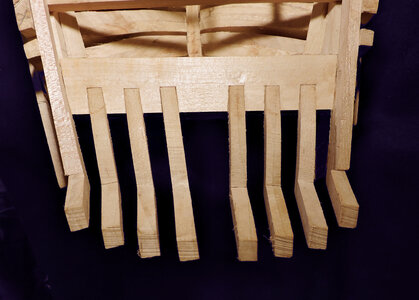
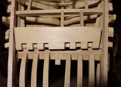
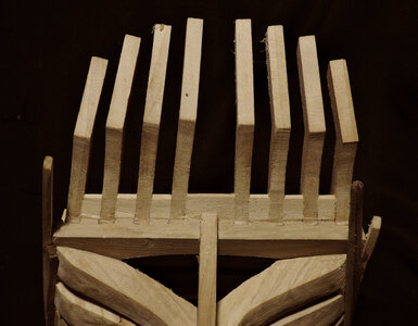
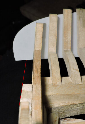
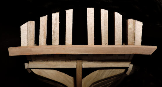
When i installed the stern timbers i used Gorilla super glue, the only area where the glue was used was at the bottom of the timber where it sat in the transom notch. All it took was a flick of my finger at the top of the timber and they would snap off. After several times i cleaned the super glue off and used Titebond wood glue. Looking at the stern structure it seemed to me it would be weak. There is very little surface area between the timbers and transom for such a long and heavy timber. The two timbers at the ends were very strong because they were fastened to the waterways, but the center ones had no supporting timbers.

timbers6.jpg
timbers7.jpg


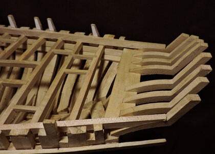
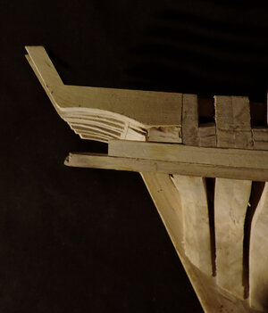
There is just one more structural timber to add to the hull and i am sure it has a name but i do not know what that might be so i will just call it the last deck timber. You know there has to be something under the deck planking like a beam of sorts for the deck planks to nail to where they meet the stern.

ws2.jpg

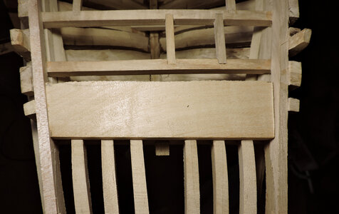
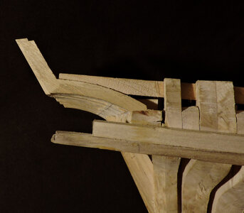
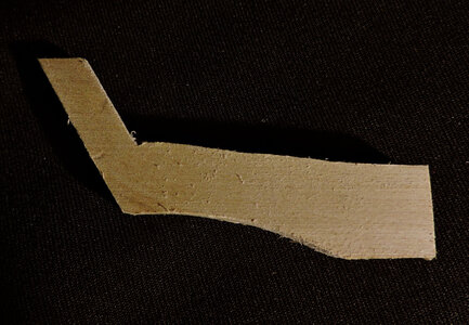
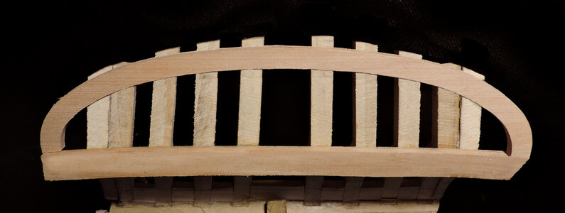
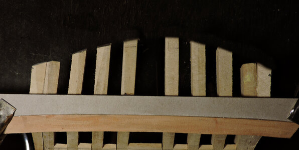
Shaping and installing the last deck timber was not easy it took me four tries. This last timber brought the end of the deck even with the deck beams. Granted i did not have to be so fussy when fitting the timber around the stern timbers because it will be totally covered with deck planks and will disappear under the deck. However, at this point i am not sure if i will even lay a deck so the timber will be exposed. Besides you see it now

beam1.jpgbeam2.jpgbeam3.jpg
 
Like i said this last timber was not easy to fabricate and it is only a taste of what comes next. From this point on all the joinery will show in the finished model so it has to be tight and right and it will be harder to fabricate and fit. So! i figure fussing with this piece just adds to my skill of minature woodworking.
The model is built using Red Maple which is not red for some reason is only a name and not really the color of the wood, but it does have a faint pinkish gray color. The hardness is like Cherry not to hard and not to soft just right for hand tools. In this case after two tries i decided to use a softer wood so i went with Basswood.

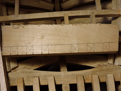
first step is to fit a piece between the waterways and against the stern timbers, Yes the timber should actually fit under the waterways but at this stage there is no way of doing that short of cutting and ripping out a section of the waterway and i was not going to do that.

beam5.jpg

i needed to mark the location of the timbers

beam6.jpg


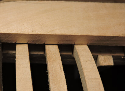
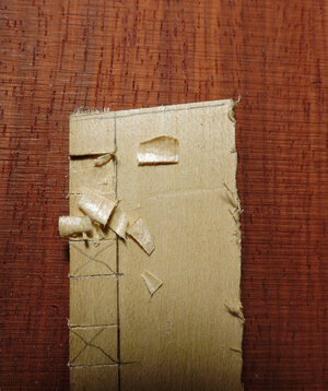
looking at the underside i marked the location of the timbers. This was one of the mistakes i cut the notches square to the leading edge. Notice the timbers actually angle inward to the center of the stern. No wonder i could not get a proper fit.

beam7.jpg

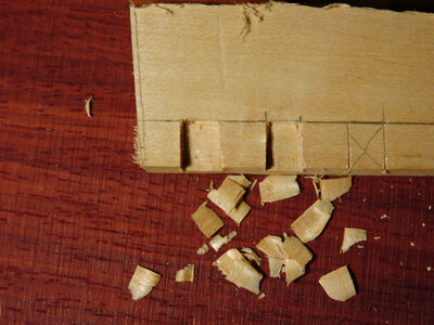
using a softer wood like Basswood i could take bigger cuts and shave down the notches really easy.

beam8.jpg

beam11.jpg

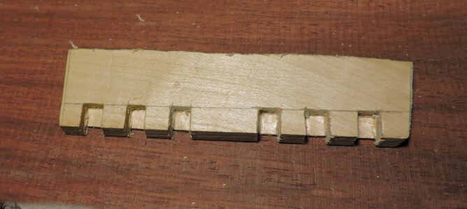
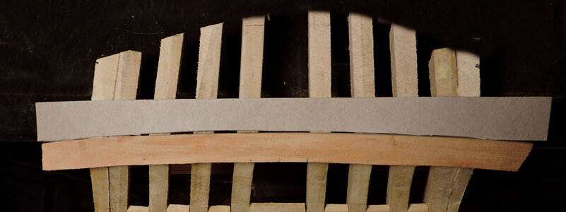
This was try number two before i figured out i had to cut the notches on an angle and i realized the arc on each of the timbers were ever so slightly different because each timber has a different shape.
What i ended up doing is using each wrong piece as a template because they were close but not good enough so i kept refining the piece until i got it all to fit.

beam9.jpg
beam10.jpg
 
Last edited:
i used Basswood for the last deck piece so a few words on using wood.

the harder the wood the harder it is to build the model if you are using hand tools or small hobby power tools. The advantage to using softer wood they are so much easier to work with and cutting things like joinery. With a softer wood you can cut a tight fitting joint and force the pieces together making a tight fit because a softer wood will give a little. A hard wood does not give at all so the joinery has to be cut exact and tight.
We all know building model ships require clamping and bending etc soft wood will leave a mark from a clamp hard wood will not. One wood being used is Alaskan Yellow Cedar this wood is so soft it is between Basswood and Balsa wood and you can dent it with a finger nail. I am not saying it is a bad idea to use soft wood you just have to take care if you are going to use clamps on it.
Hard wood will take a better finish and will cut clean sharp edges, with a sharp tool you can also get a clean sharp edge on a softer wood so you need to make sure your tools are sharp. You will not get that marble smooth, deep looking finish like Boxwood but a ship model does not need to be polished like a sculpture. I actually like a rougher finish it looks more like wood than plastic.

dent.jpg
 
Last edited:
now that the hull structure is complete you can see the design element that went into the Tecumseth. Looking at the shape it has this tear drop with a full rounded bow and the hull takes a dramatic flare then tappers back to a narrow stern. A well thought out design because at the widest part of the hull two massive 24 pound cannons mounted on rings will set.

phase1a.jpg
 
Last edited:
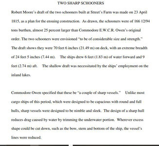
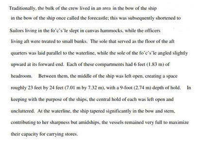
The twin schooners Tecumseth and Newash were built after the war of 1812 and were refered to as "transports" however that might be a stretch they were powerful warships heavily armed and fast. If i came across either one i would not engage at the risk of being sunk.

text1.JPG
text2.JPG

looking at the Tecumseths hull it meets the stated description it is built for speed and built strong.

phase1b.jpg

using the aid of a shadow you can see the "full body" amidship but over all it was sleek

phase1c.jpg

like all the ships built on the lakes they are uniquely designed for the lakes and for a spacific purpose. As for the Tecumseth it was not a ship you would want to mess with.

this ends part 1 of the reconstruction of the last ship of war built on the Great Lakes

part 2 will involve the fit and finish and the arming the Tecumseth
 
I am sure you all heard "i don't need instructions" i know what i am doing. Or asking for advice only to get "did you read the instructions?"

Building a model ship from scratch you would think there are no instructions, but you would be wrong there are instructions just not in a little booklet with step by step how to do something. To become a shipwright required schooling and or years of being an apprentice under a master shipwright. So the rules are out there just scattered over many years of published books and first hand knowledge. In modern times all over the web and scattered in forums.

Then again scratch building allows you the builder the freedom to follow your own methods rather than those of someone who may or many not be correct. You also have the opportunity to learn by your mistakes and learn how to "fix" those mistakes and correct problems.
To exercise my freedom what should i do now? well i can start building deck structures like coamings, companion way, skylight etc. Maybe do the hull planking above the wales.

I went out in the shop and milled out pearwood planking then came back in and sat down with the hull to plan out the planking. It did not take long to realize what i intend on doing and what the sequence of the build dictates is not the same thing.

No problem at the stem that is pretty much straight forward and where to start the first plank is also a no brainer at the top of the wale!

The issue became clear at the stern this is what is should look like.
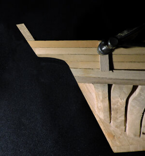
shape4.jpg

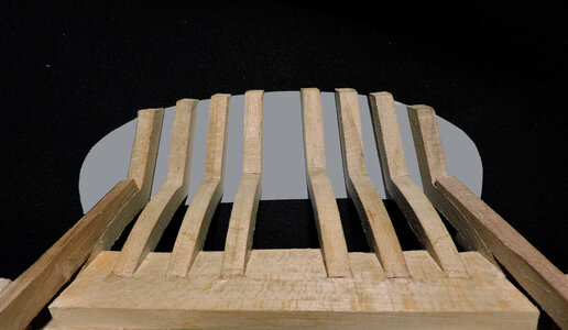
looking down on the hull there is a space where the ends of the planks are just flapping in the wind and nothing to nail them to.
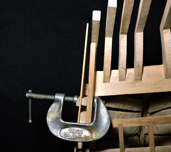
shape5.jpg

the red arrow shows the outer face of the hull frames so it seems i forgot something. the hull planking does not glue very well to air. Looks like i got my next step defined "finish the stern" first.
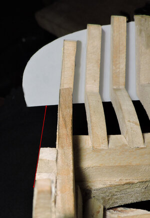
shape3.jpg
 
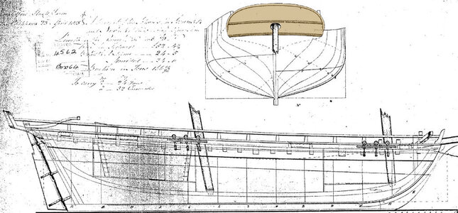
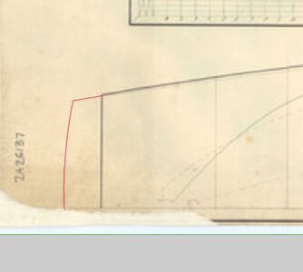
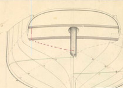
like the deck structure there is nothing on the wreck that would give a clue to the shape or construction of the stern. If it wasn't for the survival of the original drawing the stern would be a total guess. Having the drawing it is the obvious place to start.
shape11.jpg

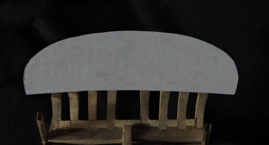
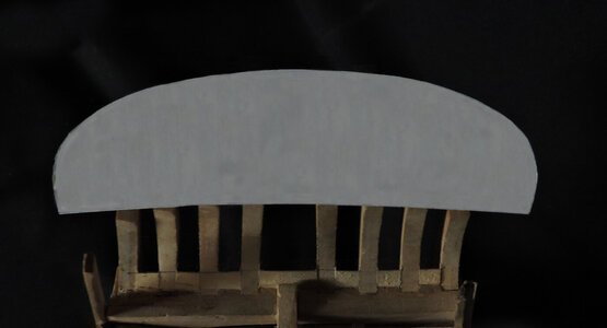
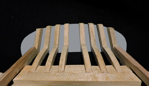
What i did was make a cardboard pattern from the drawing and stuck it to the stern timbers. This is the size and shape of the stern according to the drawing so this is what i have to work into the hull.
shape1.jpg

shape2.jpg

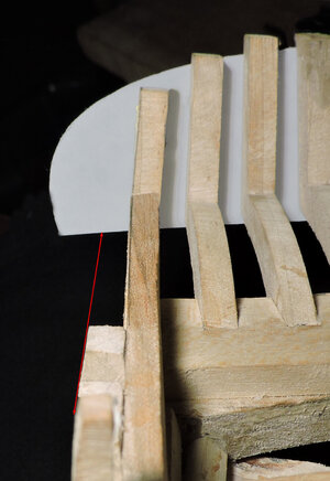
I would have leaped forward and continued on with the stern, except for one little issue the stern pattern from the original drawing is wider than the hull the red arrow is the outer face of the hull and the stern shape goes beyond the red line.

shape3.jpg

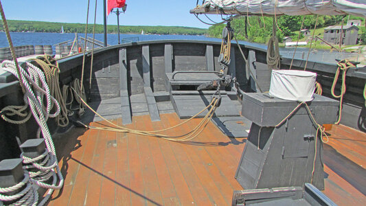
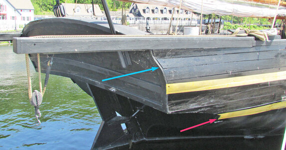
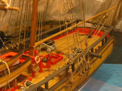
Taking a look at the Tecumseth at Discovery Harbor it is clear the stern and the side of the hull meet. But! the shape of the stern pointed to by the blue arrow does not match the original drawing and the red arrow is pointing to a molding where the main wales should be.
The Tecumseth at Discovery Harbor is built on a steel hull which means it is not a faithful reconstruction of the wooden Tecumseth and artistic interpretation is at play.

IMG246.jpg

now what? time to investigate and come up with a decision
 
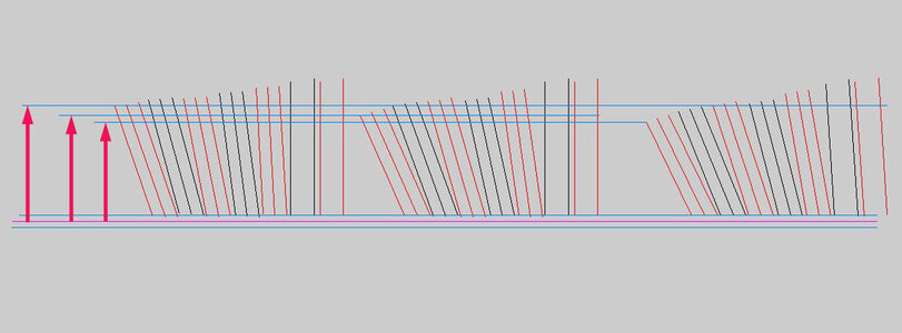
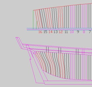
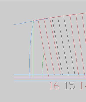
first thing to do is check the drawings so i took the cant frames in the stern and checked them to make sure there isn't an error and the hull was built to narrow. That would be a major operation to rip out the stern section and deck so much i would not even attempt it. Well maybe i might but such an error just makes you want to scrap the build.
Depending how much of an angle you cant the frames it will change the width of the hull as you can see by the red arrows.

cants.JPG

cants4.JPG
 
i traced the line of the stern that is the red line that is formed by the stern timbers.

cants3.JPG

the vertical blue line is the outer face of the hull at the stern then taking the red traced line and rotate it horizontal placing it at center it lines up with the blue line. SO! as you can see the actual stern is indeed bigger than the width of the hull.

cants2.JPG

to confirm the angle of the cant frames the last cant frame hits right on the blue line.

OMG thank you as my wife can hear me yell from the other room "the hull is built correct"

cants1.JPG
 
now it went from "fix the stern" to finish the stern"
A clue comes from a model of the General Hunter in the museum at Fort Malden. Look close at the stern area yup i see the stern sticks out beyond the hull.

h10.jpg

i have said in other discussions you really can not take what was done on one ship and assume it was done that way on another ship. The discussion on treenails used to fasten hull planking is a prime example. The British naval yards may of used tree nails but everyone else used spikes, and even the British themselves ended up using planking spikes when they built the Great Lakes fleet. How to connect the dots between a ship built by William Bell and a ship built by John Moore?

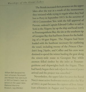
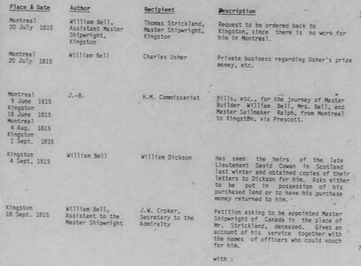
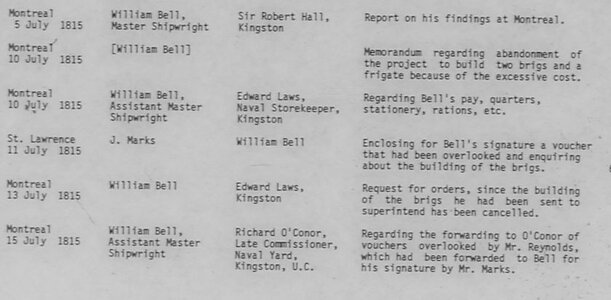
Well first in the lower left corner William designed both the General Hunter and the Tecumseth according to the information in the book.

wb3.JPG

but other sources say John Moore drew the plans and built the twin schooner. Which is most likely true because William Bell was in Montreal at the time the schooners were built. Also both John Moore and William Bell claim the title of assistant master shipwright at Kingston.
Who did exactly what is not the real point here, both John and William were working in the Kingston yard so maybe William did design the Tecumseth and had John draw the plan and go to the farm and build them.
i would connect the dots and say the General Hunter and Tecumseth had the same style sterns. Perhaps when John was doing the drawings he was inspired by Bell's stern.
Interesting there is no signature on the drawing just the date and place.

i have a good idea what to build so now i just have to figure out how to build it.

wb1.JPGwb2.JPG
 
Getting started on the stern the first thing to do is fill in the space between the outer stern timber and the outside of the hull so the planking has something to nail to.

shape6.jpg
i traced the shape of the space and cut out a filler piece

shape8.jpg
fitting the filler piece and sanding it even with the hull

shape7.jpg

on a historical note i thought that filler piece would be really heavy in White Oak. But i found references to Live Oak and White Oak were used only for the frame floors and the upper futtocks and and filler blocks were either Pine or Cedar. So the filler block at the stern would not be so heavy.
 
I sat around for a few days thinking about the stern, cutting out cardboard patterns and planning how to approach the build.

This is the shape from the plans so this is what i have to work with

shape1.jpgshape2.jpg

and this is how much the stern goes beyond the hull

shape3.jpg

i figured i would start with the lower molding where the upper and lower parts of the stern meet. The molding is cut a bit wider because the bottom edge will have a bevel where it meets with the lower planking. Once the lower planking is in place i will sand the molding to meet up with the plank edge.

shape12.jpg


Taken from the drawing i cut out the top molding and set it on the stern. This gives me a visual of the size and shape of the stern. The timbers will later be sanded down to the top of the molding.

shape13.jpg
 
Last edited:
Fitting planks to the lower molding and fitting tight to the upper molding will be a challenge so i will cut and fit the planks off the model the assemble the stern from finished planks.
first plank rests on the lower molding so i rough cut a cardboard template

shape14.jpg

with a piece of sandpaper i refined the curve until i got a tight fit.

shape15.jpg

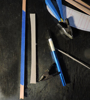
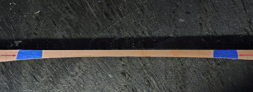
satified with the arc i transfered it to the plank. i never draw a line i always use tape and cut the line because it gives me a sharp edge to work to.

shape16.jpg
shape17.jpg

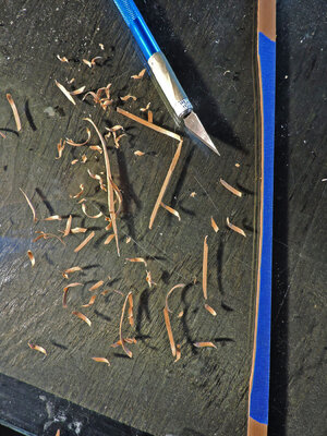
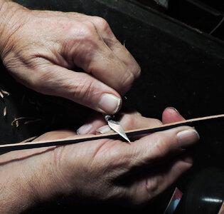
A table saw is quite worthless when it come to cutting curves, a scroll saw will work if you are careful and can cut a clean line. My method of cutting joinery, arcs and curves or where edges meet i do by hand with a knife and sandpaper. The cut you see is wavy and i will refine it a little more before i sand it.

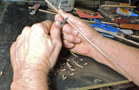
For a piece like this i pinch it between my finger and thumb resting the strip on the base of my thumb and holding it there with my second finger, then using a knife in my hand and resting the knife hand against my hand for support i take off shavings. i can cut a very, very fine shaving. When i am close to the tape edge a few passes with sandpaper and i get a perfect fit. The blade is new and sharp that is important.
Now this is "my way" of woodworking at a small scale and it took practice. Learning to use a knife is a great basic way to get into carving.

shape18.jpgshape19.jpg
 
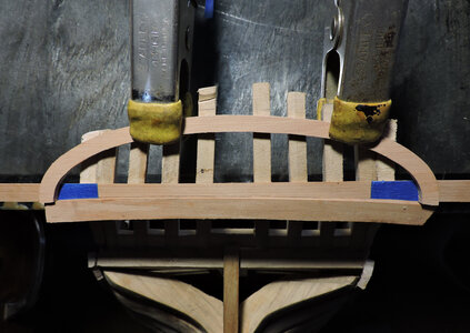
Once i have a tight fit between the first plank and lower molding i clamped the arc molding to the stern timbers and slid the first plank in place. By clamping the molding it acts like a weak spring and holds the plank in place while i cut the tape.

shape20.jpg

next is a matter of cutting and sandings the ends to the edge of the tape

shape21.jpg


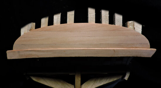
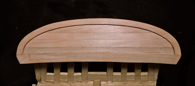
The first plank was glued in and i did the same with each plank, clamping the arc to the stern timbers and sliding the next plank between the molding and stern timbers.

shape22.jpg

the final step is to glue the arc around the planking. Each plank is a different width and i did that so i would not end up with a narrow sliver of a plank at the top.

shape23.jpg

With the upper part of the stern done the next step is to work on the lower section . Because there are no building instructions or pre cut parts each step of the build begins with a thinking intermission from actually building. When i am in planning mode i like to see the step from start to finish so i do not do something that has to be ripped out or changed. Or realizing i should of done that first before i did this, now it is way more difficult.
 
That stern looks very good Dave! My sincere congratulations on that!
 
thanks Heinrich

at this stage of the build it is more about fit and finish so care is needed with every cut and every part.
i even go through my milled planking to select color so each plank has a slight difference so they stand out from one another. If you make the seam to tight and each plank the same shade of color they will blend together, i want an ever so slight difference between planks. The center plank seam almost disappears.
 
Back
Top