Tecumseth 1815

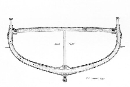
back to the Tecumseth here is a section drawing by John Stevens

img137.jpg

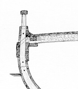
looking closer it does indicate the deck beam is notched into the deck clamp i am not sure what the square piece is at the side of the deck beam. It might be a carling or a filler timber like Echford used. You can see dotted lines indicating carlings on the other side of the beam and solid squares on the facing side, so the squares along the sides are most likely carlings. The waterway looks like it sits on top of the beam and not notched into it. I have no clue what the timber is below the deck beam is.


img137a.jpg
 
Last edited:
MP68a.png

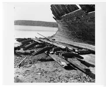
image credit to the Maritime Museum of the Atlantic, Halifax, Nova Scotia, a part of the Nova Scotia Museum,


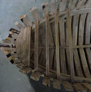
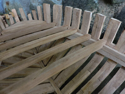
in this image there is a piece of the side of the hull which can be at the location of the wale and clamp. The timber on the outside of the frame fragements is quite heavy so it may very well be part of the wale. On the inside of the frames there is a heavy timber. Look at the end of the timber in the lower right and you can make out the remains of a scraf joint, now moving up a little you see the edge of what looks like a notch corner by the spike sticking out. John Stevens had a section or sections of the hull by the deck clamp so he would have noticed if knees were joined to the clamp and drew them in his plans. There might of been at least part of a kness but nothing was mentioned of knees.
Conclusion: it is unlikely knees were used in the deck construction of the Tecumseth which does go along with the other ships and methods.
 
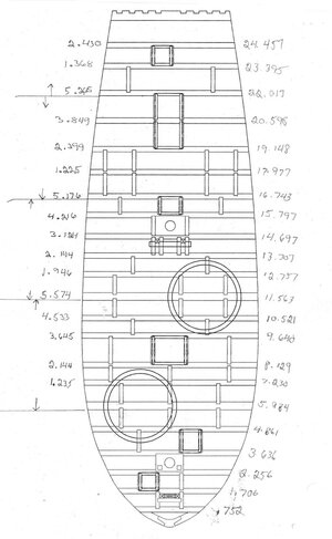
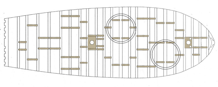
deck construction begins with a plan. This is the layout of the beams, hatches, companion way and mast partners. I am going to build this deck by the numbers which you see on either side. On the left the deck is broken down into segments and the measurements are from the forward face of each frame to the next. On the right are the measurements from the front of the breasthook to the forward face of each frame. I use 2 sets of measurements to counter check the location of the beams to make sure i am not running long or short over the length of the deck. I learned the hard way by starting a deck at the bow and by the time i was at the location of the beams at the main mast i was off by 1/4 inch. Tiny errors all along the way do add up to a much bigger error down the line.

Under the circles is a heavy beam which supports the 24 pound guns. When i drew this layout i did not include carlings running along each side. At the time i did have the information there were no deck knees so i place the carlings were i thought they would do the most good like under the guns, along hatches and to support beams for the pin rails. Also it is an unknown how the breasthook was assembled. I drew it in three pieces using a butterfly to join them. On the prototype i simplified it and made it in one piece.

The purpose of documenting difference in possible construction methods makes my model mine and your model yours. So yes you can shift carlings, add side carlings or ledges there is no absolute right or wrong. Just like the real thing each ship was a one of a kind

deck plan.jpg
 
construction of the deck begins with the breasthook, that is the piece at the bow. There are all different configurations as you can see i drew it as two pieces joind with a butterfly joint. What i drew and what i did are different because the breasthook will be covered by deck planking and that butterfly joinery is quite fussy and it takes time.

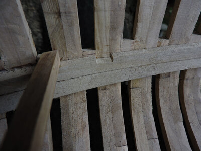
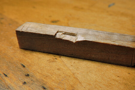
I am going from the breasthook to the first heavy beam the gun sits on. Each beam sits in a notch cut into the top of the clamp, you can see a notch on the right.

DC5.jpg

DC1.jpg

This completes the first section now i will use the heavy beam as my starting reference point and set the next section of the deck.

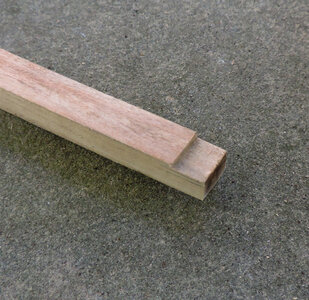
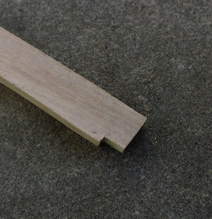
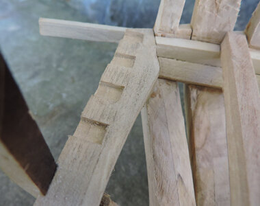
The gun beam is bigger than the rest of the beams so i cut a notch in the end of the beam so it sits flush with the rest of the smaller beams. The rest of the beams do not have a notch in the end of the beam. This beam will take all the recoil from the 24 pound cannon sitting on it, so i notched both the beam and clamp.

DC2.jpgDC3.jpg

clamp notch

DC4.jpg

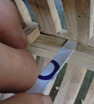
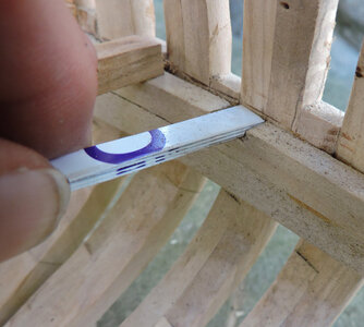
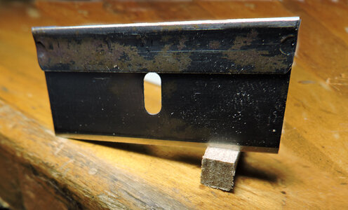
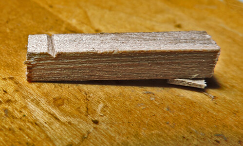
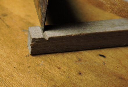
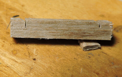
the deck beams are laser cut so they are all exactly the same size. When setting the beams into a notch the notches should be as close to the same depth as possible. What i did was a DIY feeler gauge and cut strips of a plastic gift card and glued them together. I went along and measured the notches as i cut them, and might as well get use to cutting notches because there will be a lot of them.

DC6.jpgDC7.jpg
 
Last edited:
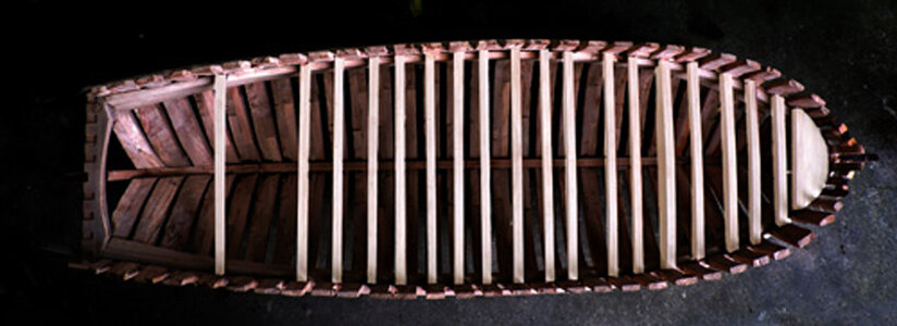
it would be redundant to build the deck beam by beam so i will fast forward to the last section at the stern. The Tecumseth was built as an armed transport to carry heavy guns. As you can see the deck structure is built strong with beams close together and no room for ledges between the beams. The wider space to the left is where the cabin goes. The second last beam at the stern would have the front cabin wall under it.

Like the Caustic the British like putting really big guns on small ships the Tecumseth carries 4 heavy guns and two extra in the hold. When i look at the design and heavy construction i think a "transport" is a cover story for an armed war ship. There sure isn't very big hatches for a "transport"

DC9L.jpg
 
Last edited:
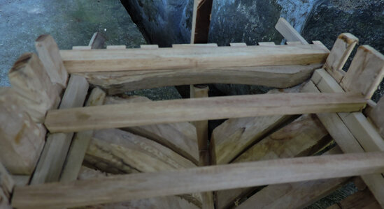
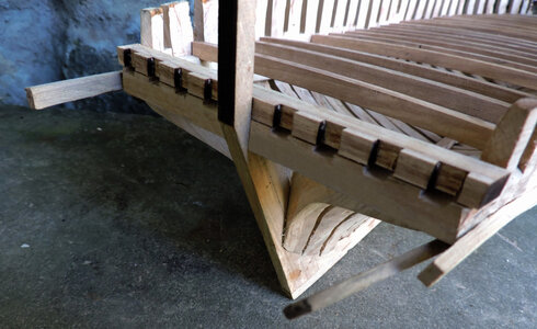
reaching the stern the top of the deck clamp is at the same height as the top of the transom. The ends of the deck planking will have to sit on something at the stern.

DC13.jpg

That something is a timber the same thickness of the deck beams and it will sit on top of the transom.

DC12.jpg

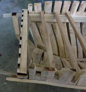
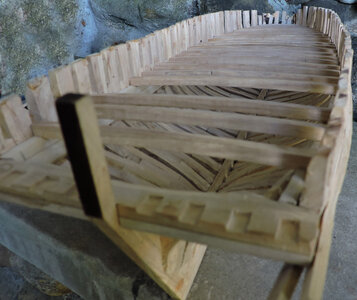
looking from the top down and from the stern it is notched to go around the stern timbers. At this time the stern timbers will be left off until the upper works and stern are built. There is still some rough handling of the hull yet to be done and the stern timbers can easly be broken.

DC10.jpg

DC11.jpg
 
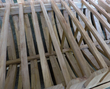
Oh no! i built myself a problem. When you do not have any sort of instructions or anything to help you along with the build like in building from scratch, sometimes you make a big mistake. After i put all the deck beams in place i realized each beam had a post under the beam that sat on top of the keelson. The deck beams are to close together so i can not get my fingers between the beams to place the posts. Now it takes needle nose pliers and a lot of dropping the post and fiddling around to set them in place under each beam. I would have been so much easier to install them as i placed each beam.

DC14.jpg

There are a lot of post to place under each beam, oh me oh my doing things the hardest way possible. I thought of ripping out the beams after
20 minutes of trying to fit just one post. I thought i was going to just jump right into fitting carlings and the waterway, guess not.

DC15.jpg
 
Last edited:
I thought maybe cutting the notches in the beams for the carlings after the beams were in place, after the post issue now i am doubting myself if cutting the notches after the beams were placed or should i have cut the notches when the beams were free of the hull. Hum? i spooked myself, well i will find out shortly.
 
reaching the stern the top of the deck clamp is at the same height as the top of the transom. The ends of the deck planking will have to sit on something at the stern.

View attachment 258513

That something is a timber the same thickness of the deck beams and it will sit on top of the transom.

View attachment 258514

looking from the top down and from the stern it is notched to go around the stern timbers. At this time the stern timbers will be left off until the upper works and stern are built. There is still some rough handling of the hull yet to be done and the stern timbers can easly be broken.

View attachment 258516

View attachment 258515
I really like these views of the stern. All the various members coming together.The species of wood you used , to me , adds to the look.

As a side note, where I live are nice old barns that are fun to look at when I have a chance.

Our community planned a day to visit a group of barns the owners were kind enough to allow an open house . I had an eyeful looking at the various points of connection. I even learned what a threshold means.

All in all you ship is coming out very nicely.
 
I really like these views of the stern. All the various members coming together.The species of wood you used , to me , adds to the look.

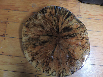
the wood i am using is a hand selected Red Maple also called Soft Maple, the wood is about as hard as Cherry. At it's extreme when it becomes spalted it looks like this and becomes very colorful.
The Tecumseth at a larger scale allows more of the wood figure to show as apposed to smaller scale where the parts are so small the figure in the wood is cut away.
Using a wood with a figure is a contrast to some ship modelers who stress the use of wood with very little figure and an even color. Once this model is given a coat of Tung oil it will turn a honey color with shades of yellows, golds and mellow shades of reds. I think it will be strikingly bold.

DSCN3116.jpg

There are two different approaches to model ship building one is using all the same wood or woods that are close to the same color. This shows off more of the joinery and workmanship. The other approach was termed "painting with wood" and is more like marquetry where the wood is the main show. Some consided this a distraction to the subject which is the ship model. I have done both and both methodes produce a striking model.

marquetry-panel.jpg


As a side note, where I live are nice old barns that are fun to look at when I have a chance.

Our community planned a day to visit a group of barns the owners were kind enough to allow an open house . I had an eyeful looking at the various points of connection. I even learned what a threshold means.


i grew up in the farm lands of Ohio and spent many hours looking at the construction of barns called post and beam construction. The hand cut joinery is amazing.


All in all you ship is coming out very nicely.


thank you for the complement
 
next step is adding the carlings to the deck those are the shaded pieces. There will be a lot of notch cutting like over 100 notches to cut into the deck beams. It may look random but actually the carlings are placed to frame in deck structures and supports under the guns.

Like the deck beams this is a mass production job of cutting notches so i will show how i set things up and then go ahead and cut all the notches.

carlings.jpg


I gave the carlings some pre planning and how i was going to accomplish the task. My first idea was to cut the carling notches before i installed the deck beams. Doing it that way introduced variables. First you have to make sure once the notches are cut the carlings will be square to the beam, then each beam will have to be set exactly in position from side to side so the carling is not at an angle. I decided to place the beams in the hull first so they are securely in place then cut the notches.
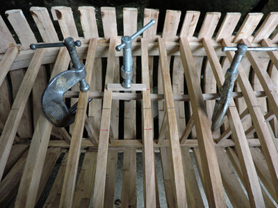
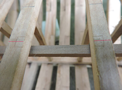
first i marked the center of the deck with a line, all the carlings will be measured from center. The setup is to first clamp a piece of wood under the beams crossing where the carling will go. a carling is cut to length so the ends are half way across the top of the beams. A third clamp pinches the caring tight against the beams.

DS16.jpg

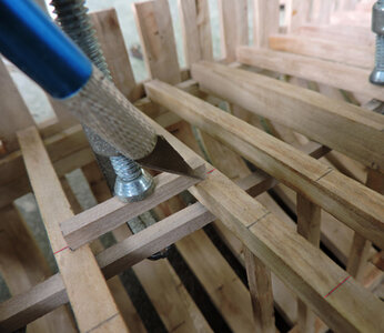
Holding the carling in place is important so it does not slip while you cut a score line against the sides and end.

DC16.jpg

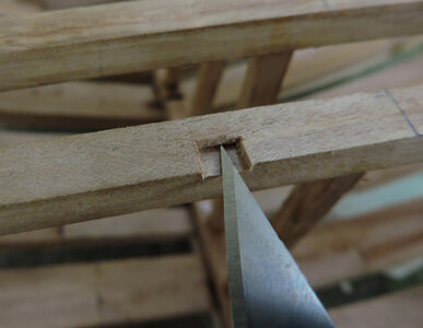
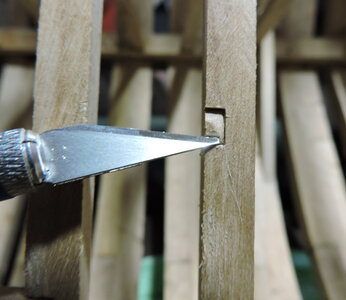
Don't try and make a deep cut just make a deep enough score line, you can deepen the cuts a little at a time as you cut the notch.

DC19.jpg

As you deepen the score lines they become the stop cut and you can shave the bottom of the notch to the cut lines. I buy Exacto blades by the box of 100 because i will keep using a new sharp blade for work such as joinery.

DC17.jpg

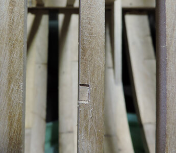
My fear of not being able to get an even deep notch while the beams were in the hull because adjoining beams would get in the way did not happen.
It is the larger scale giving me enough working space to make a clean deep notch. The wood you select also makes a big difference you can select a hard wood and struggle with chipping out tiny pieces or use a workable wood that you can make easy clean slices.

DC18.jpg

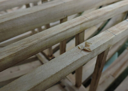
There are 57 carlings to install and 114 notches to cut, i timed the first notch and it took 2 minutes. 114 x 2= about 2 hours of notch cutting time not to bad.
 
a progress report on installing the carlings, i know i said it only takes a few minutes to cut the notches but it is the "round to it" that stalls the process. Cutting the notches at the sides of the hull turned out to be a bit harder than the ones in the center because you do not have much room against the sides of the hull to get the correct angle of the knife.

carling progress.jpg

if you miss cut a notch or mess up in any way at this point it is harder to cover the error so yes it is a little bit of a stress making sure each and every cut is as good as you can get it. A trick i learned over time is to have a set system that gives you better odds of making tight joinery. If you do exactly the same thing over and over the chances of success is much greater. For example

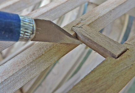
cutting the notch in the beam

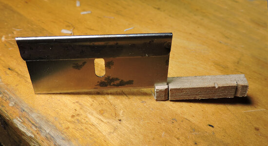
never use a pencil to mark anything always cut a tick mark. A blade cut is way thinner than a pencil line.

c7.jpg

when cutting a notch it happens a lot when you overrun the stop cut and end up chipping the edge, there is no recovery from a chip error.

c11.jpgc12.jpg

To avoid chipping the edge of the notch start your cut in the center and cut down to the edge never ever across the notch. You will end up with a pyramid shape in the notch.

c8.jpg

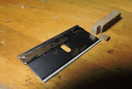
now take a level cut across the notch, notice i use a blade with the end ground like a chisel, this helps a lot in keeping the sides of the notch clean.

c9.jpg

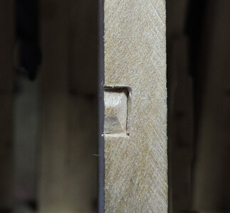
end result you will always get a clean sharp notch. You can now deepend the notch without fear of chipping the edge.

c10.jpg
 
Last edited:
notches in the end of beams and carlings.

using the tick mark as a guide place a razor blade in the tick mark and rock it back and forth to make a score line

c1.jpg

on the side of the notch cut a V down to the score line

c2.jpg

the reason for the V cut is to guide the razor saw it will sit in the botton of the V and along the side of the score line. I realized by cutting along the any line the part is slightly short every time. The reason is the set in the saw teeth actually depending on the set the cut is cutting past the marked line. In a V the set of the teeth is against the side of the score line.

c3.jpg

Every cut is perfect and tight.

c4.jpg

turn the piece on the side and split the notch out

c5.jpg

c6.jpg

it is a bummer when you finish 5 out of 6 notches in a beam and mess up the last one, you know you have to rip out that bean and redo all the notches. Practice make perfect once you got the mussel memory it does become so much easier and few errors.
 
still hard at work notching all the carlings and framing in the deck. I am thinking another 5 to 7 days of deck construction then we will take a look at a few pictures and on to the waterways and bulwark stanchions.

As i build i am liking the Skelton look of the model. it is wide open and shows the construction and timbering along with the joinery, i may install the guns and stop at that point and not add any deck or hull planking.
 
i read a lot of comments on kit instructions or lack there of. To make a bold statement you do not need instruction, for example a patient does not come with instructions a doctor "knows" what to do, a carpenter does not need detailed instructions for every house he builds because he is a "carpenter" and knows the construction of a building. Same with a Mason he knows how to lay brick or stone so he can build anything. This also applies to ship building if you are a shipwright and know and understand the basic principles you can build a ship be it from a kit or scratch.
From this point on the Tecumseth is built from ship building knowledge, logical construction methods and known ship building practices of the period. There are no "instructions to follow".
deck finished100r10.jpg

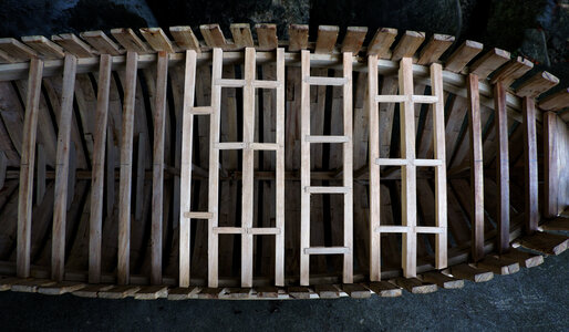
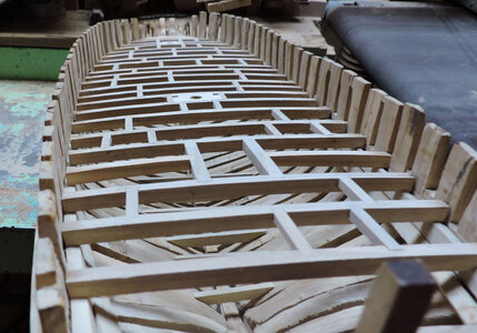
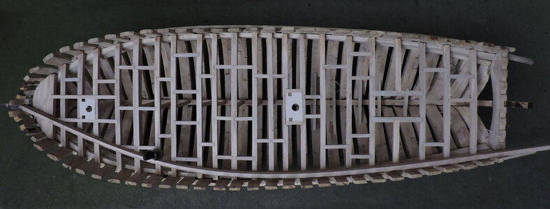
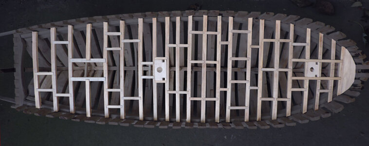
the deck structure is now complete and it looks like random beams and carlings but actually there is a logical reason why the carlings are where they are. A drawing of the deck layout did survive so we know what it looked like but there is no constructiuon detail and nothing survived on the wreck. The deck construction you see is a "reconstruction"
deck finished100rc10.jpg

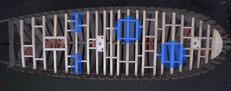
the red tinted areas are hatch ways and the companion way and skylight so those carlings frame in the five hatches so the coamings can sit on the beams and carlings. The blue tinited areas are where guns will be placed so those carlings are acting as supports for the heavy guns. I found it interesting how solid and strong the entire deck became once all the carlings were in place.
vice1a10.jpg
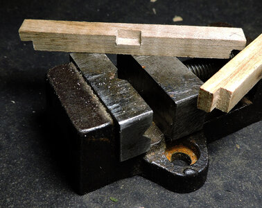
it is much easier cutting the joinery off the model and in a vice rather then and cutting the joinery on the model. You get clean and sharp joinery because you have more movement with the knife. you may wonder why bother with cutting a clean, square sharp notch when it will be covered? Well let me tell you
vice2a10.jpg
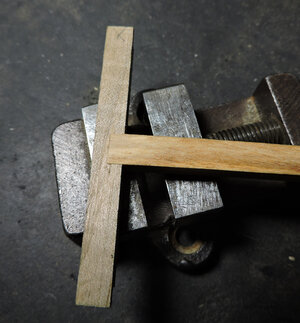
this is why, when the notch is clean and sharp the final fit is tight.
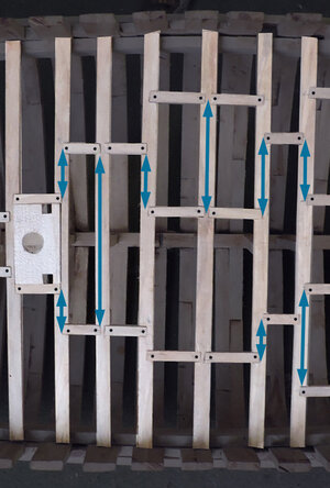

deck finished spacing.jpg
i chose to cut all the joinery on the model because all the carlings line up from beam to beam and with one another. So all the dots have to be exactly in the right place. Taking the deck apart and pulling out the beams to cut the notches for every carling seemed to be a real big problem making sure everything will line up from side to side. That is a lot of dots so i glued in the beams and placed carlings in one at a time right where they should go.

The model being at a large scale of 3/8 = a foot gave me enough room to work.
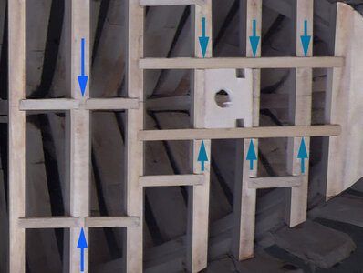
long carling2a.jpg
What we are looking ar here is builders license or "doing it my way" when two carlings are in line with each other it creates a space on the beam pointed to by the arrows on the left. That beam is wider than the rest of the beams because it is the one the gun will sit on. The rest of the beams that space is pretty small. On the right is a long carling and as you can see there is no space on the beams between the carlings. Some expert on deck construction may argue you can't do that carlings notch between beams from beam to beam they do not cross a beam.
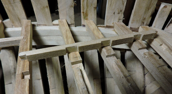
long carling3a.jpg

Well i say so what my logic is these beams will take a lot of stress because of the mast, pin rail up right posts and the samson post where the bow sprit ends so to me it was logical to make a long carling notched over the beams locking them in from side to side and front to back. Then again some shipwright might think hum? good idea. Whatever! thats what i did.

all in all a final comment on building a deck it was more a feel of "woodworking" than assembling a kit. Personally this is why i scratch build to have to figure out what and how to do something and the fabrication of parts and wood working rather than assembling prefab parts.
 
Last edited:
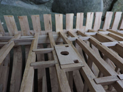
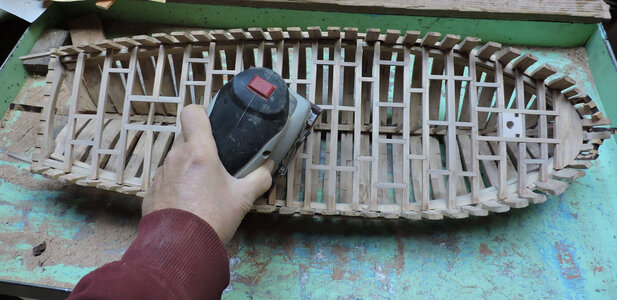
when cutting the notches in the beams and carlings i did not always hit the exact level as you can see in the picture and some of the carlings were a little to high. They look much worse than what they really are, actually they are about the thickness of a plastic credit card or about half a mm. I could have taken more time and cut the depth of each and every notch making sure the carling sits flush with the top of the beams. But 1/3 way through the job of building the deck i began to wonder if i will ever get this done. So i did get a little sloppy with fitting the joinery. When you think about it building the model at 1:32 scale i am working within a tolerance of less than a scale inch.
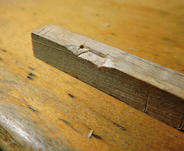
sanding4.jpg

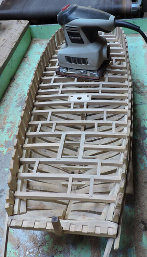
OR better yet don't worry about trying to be exact when cutting the notches and take a sander to the deck. The larger scale makes it possible to use bigger tools. The deck does arch from the center to the sides but not to worry you are not taking that much off, just enough to even everything out.

sanding1.jpgsanding2.jpg

and there you have it, a nice even built deck, and it look quite pretty when sanded i would hate to cover all that work with deck planking. It crossed my mind to use planks of a transparent tinted acrylic plastic for decking. You would see a deck and still be able to look through it and see the structure under the planking.

sanding3.jpg
 
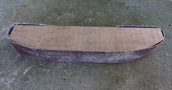
when sanding something like the deck with a sanding block don't use a square edged block the square edge gets caught or digs in. I cut myseld a sanding sled and round out the ends. This way the sled glides over edges or uneven surfaces.

sanding sled.jpg
 
Last edited:
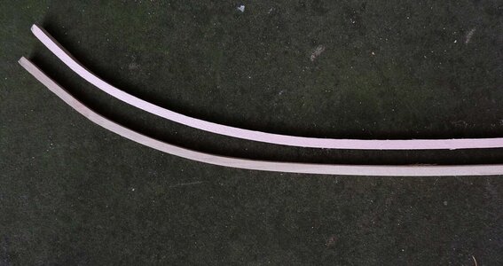
the deck is finished and time to move on to the waterway. I did a test and this is how far it will bend cold. There is no way i can bend the waterway around the bow without it breaking or breaking the tops of the frames. No doubt about it this timber will have to be steam bent.
It makes me wonder how the waterways were installed were they bent or cut to shape? Because deck knees were not used on Great Lakes ships this was a large timber about the same size as a keel timber. From other wrecks the waterway around the bow were short timbers at around 6 feet long so my thinking is there were cut to shape, and that would take quite a big hunk of timber to cut a curved piece.
So i will try to bend the waterway on the model and if that does not work then i will cut the curve.

waterway1.jpg
 
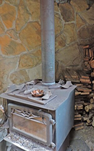
From my test i knew the waterway was not going to bend cold so i soaked it in water for 1/2 an hour and first bent it around the hot stove pipe and instant steam. It bent with no problem and the heat dried out the wood.

waterway5.jpg

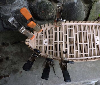
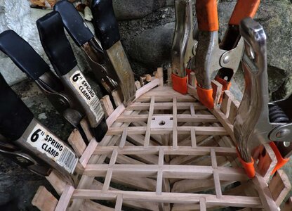
next i soaked it again this time for about 10 minutes and clamped the waterways to the inside of the frames. It bent like a piece of rubber because first off it was pre bent with steam and it did hold its bend. Second i used a wood that is actually bendable, that helps a lot.

waterway2.jpgwaterway3.jpg

the waterways at this point were still wet so i kept them clamped in place. Next day when they were dry i removed them and they held the bend with no problem. Well there was a slight spring back but not enough to really matter.

waterway4.jpg
 
Back
Top