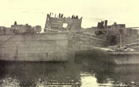
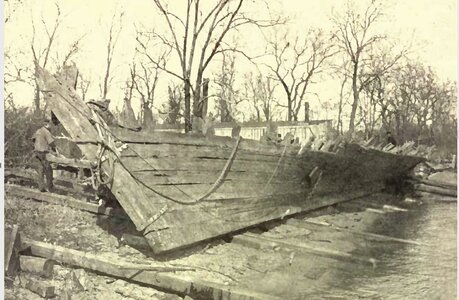
Tecumseth 1815

i am using Red Maple because i found this wood to be a top wood for model building and cutting joinery. It is a few steps harder than Basswood and cuts so smooth and even.
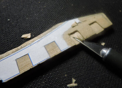
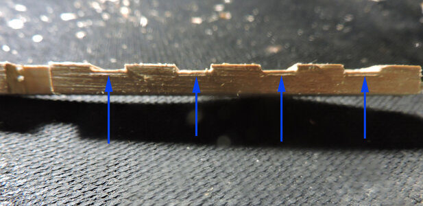
Step one is to print out a pattern of the wing transom and make a stop cut along the notches.

C2.jpg

my first cuts are at a steep angle toward the stop cuts. I do this so i do not slip and damage the edges of the notch

C3.jpg

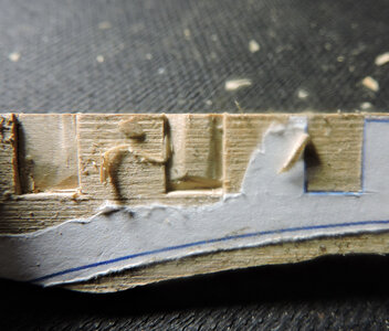
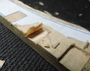
now i can take slices of wood from the center of the notch to the edge. Some modelers say to get the best and most accurate results for joinery you should use a mill. i say all you need is a sharp blade and a workable wood. The harder the wood the more you have to maintain a very sharp edge on your tool. some woods are so dense and hard you are no longer taking fine slices off you are chipping away at the wood.

C4.jpg

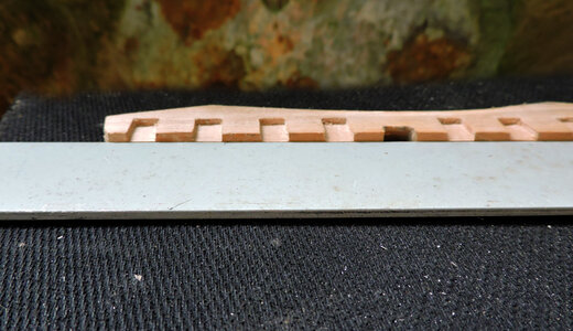
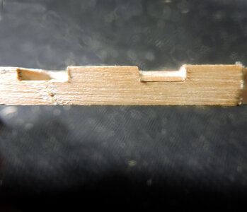
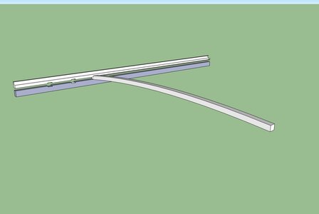
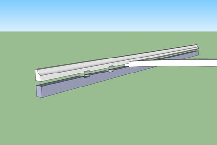
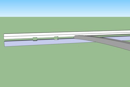
About that mill, these notches all have to be the same depth, going back to the 3D model you see the length of each stern timber forms an arch at the top so they all set even in the notch. Do you need a mill to make sure each notch is the same depth? Not really all you need is a straight edge and shims to set the proper height.

C7.jpg

Make a sharp cut along the top of the straight edge

C5.jpg

take a closer look shave the bottom of the notch to the cut and you will be within a thousandth or two.
You can hand cut joinery as accurate as a mill.

C6.jpg
 
Last edited:
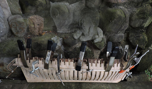
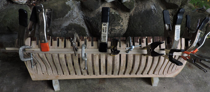
because of the larger scale of the model the wale timbers are much bigger than your average scale kit model. It took me four tries to bend the wales, they tend to snap around the bow section even after soaking and pre bending the timber.
once i did get a timber to bend i used Titebond wood glue and lots of clamps.


w5.jpg

The wales are made up of 2 timbers and i tried to bend both at one time and that did not work at all so i bent one at a time.

At this point even having the filler blocks glued between frames the hull was still weak and frame broke away from the filler blocks. You have to man handle the hull when bending and clamping.
This first wale timber sets the sheer for the hull from the wales to the caprail and down to the gardboard. What i did was take the measurement from the top of the hull to the bottom of the wale and used that measurement when bending the wale. I did not exactly hit my mark because the sheer or arc of the wales from stem to stern depends on the shape of the hull. In order to get a nice curve the hull shape plays a big part.
In ship building there is a golden rule that states

A fair line supersedes any given measurement.

that is the secret of good drawing and ship building, many a builder tries to adhere strictly to the plans, not realizing the plans are a general concept of what you are building and not the final result.

it will take awhile to install the wales and clamps because there are eight timbers to bend and add to the hull. Each timber is soaked clamped to the hull, then let to dry over night then depending on how many times it takes to succeed in actually gluing the timbers without breaking.

so in order not to see post like this

@#%^ broke another one

good god #@$%t3 holy #@$%^ broke again

i will just go ahead and complete this step and get back to you all
 
Hello Dave,
looks like you might get to finish this model by the enthusiastic way you are building it. Good work.


interesting comment Bryian

most modeling projects i do are not taken to a finish they are prototype builds and proofs of concept or just testing ideas and methods of building. Once i got that the model is done.

this project is a lot of fun because first off the larger scale is interesting the timbers seem so much bigger you get a feel of wood working rather than model building and assembling tiny parts.

there is no going wrong you can make parts or redo something over and over until you figure it out.

i also see the model more as a prop for a build log rather than a finished display model. The enthusiasm is building, photography, drawing, and just sitting and thinking about it.
 
the second wale went a lot easier than the first one, this time there was no breaking.


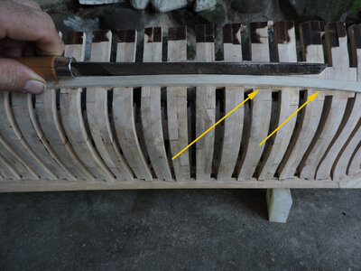
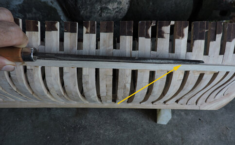
before i glued the second wale there was a slight missing the mark which you can see pointed to by the yellow arrows. This was not very much but what happened it created an ever so slight rise in the curve of the sheer.

w0.jpg

the "bump" shows at the end of the rasp. A few strokes and the rise in the wale was taken out and blended into the curve of the sheer.
Now the second wale laid nice and even along the top of the first wale. This worked out great with two timbers making up the wales. Any errors in the sheer can be adjusted between the two timbers. After the 2 wale timbers were on the hull it was impossible to detect any adjustments that were made.

wA0.jpg


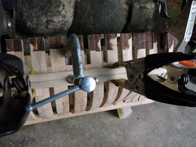
it does take a lot of clamping to secure the wale in place.

w6.jpg

Again with a larger scale the timbering is larger so the second wale can be clamped to the hull as well as to the first one making a nice tight fit.

w7.jpg

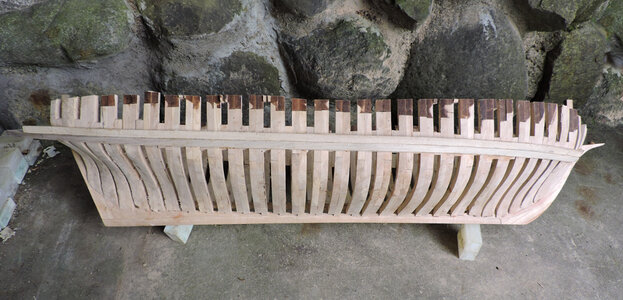
removing the clamps everything look good. I must say with the 2 wale timbers glued to the hull made the hull very strong. At least on the side where the wales are.

w8.jpg
 
Last edited:
My favorite part of building a ship model. Always have loved the backbone of the ship. Frames, keel .
Your "presentation of the reserch, design, and building of the prototype" is well received.
 
My favorite part of building a ship model. Always have loved the backbone of the ship. Frames, keel .
Your "presentation of the reserch, design, and building of the prototype" is well received.

thank you for the very nice comment

like you being interested in the backbone of a ship, in my early days the structure interested me more than building a model that just looked like a ship. I wanted to know how it was built.
i grew up in the farmland and barns were as common then as McDonalds are today. I would explore these old structures that were still standing a 100 year after they were first built. A ships structure is a master piece of engineering and workmanship.

when i left commerical art i went into the tree business with my brother, there i gained an appreciation of the sheer size and weight of logs
and timber, ship were built using huge timbering how it was cut, moved, shaped, and joined together just fascinated me.
 
The other side i did it a little different, pre bending the wale proved to be a bit of a problem, i was breaking to many pieces around the bow.
Time to experiment with another method. The first side i just soaked the wood in hot water first for about half an hour and also for a couple hours and that did not seem to make much difference. Sometimes just soaking the wood does not work you need steam which is hotter.
In the winter time i use the pipe on my wood burning stove, i soak the wood and steam bend it around the pipe. Well it is summer so i need a different method.

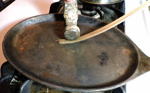
Using this cast iron skillet i poured some water on it and brought it up to a boil

w11.jpg

Using the head of a hammer i rolled it along the wood until the water boiled off. Wet the wood again and used the hot surface and when the wet wood hit the hot pan i got instant steam.

W12.jpg

at this point the wood is hot so i bent it around the bow and got a perfect instant bend

W13.jpg

all the way to the very end i got a tight smooth bend. Steam bending works way better than just soaking the wood.

W14.jpg

notice in this picture the lower part of the wale is already in place

W13.jpg

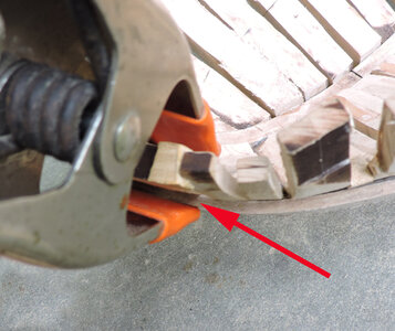
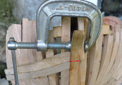
i set that wale up by first clamping a stop at the stem

w9.jpg

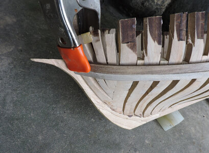
when clamping the wales to the hull they tend to creep upwards at the bow. Wales should be the same height on both sides of the stem so the clamp is placed at the top of the bottom wale and along the hull the bottom of the wale was marked. On this side i was more careful in clamping the wale to the marks.


w10.jpg
 
while on the subject of the wales they were painted black so some builders use Ebony or Africian Blackwood which is from the rosewood family.

both these woods are extremely dense and brittle you would have to laminate thin layers or carve the wales to shape. Bending them would be difficult.

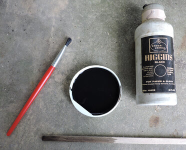
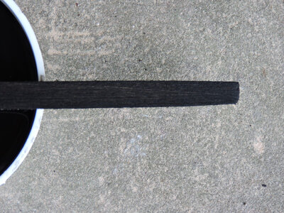
If the real wales were painted then i thought to try and create a scale painted look. It took just a drop of ink in water to turn black. The wale is one wash of the water down ink.
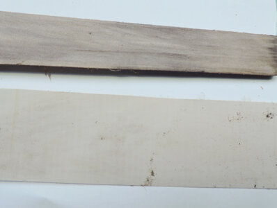
Some woods do not take an even stain some do. I am using what i call dirty Poplar which is Poplar that has gray staines running through it.

ink1.jpg


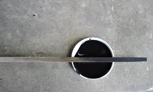
you can control the depth and coverage of the ink by multable washes

ink2.jpg


from a weathered black where the paint is almost worn off

ink3.jpg

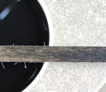
\
to as black as you want to go and notice you still see the wood grain the ink soaks into the wood and does not sit on top covering the wood.

ink4.jpg

this is my preference i like it somewhat dark but enough wood showing through to give it a weathered look. A rubbing with wax and it will give the wales a mellow sheen like worn paint.

ink5.jpg

the top piece is dirty Poplar the bottom is Holly, the Poplar has tones and a figure of shades of gray by washing over it with water down India ink those color tone show through.

color.jpg
 
Last edited:
BULWARKS

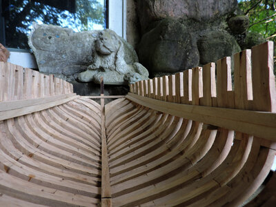
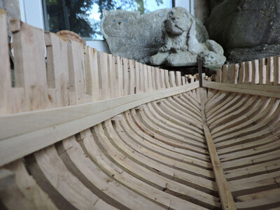
with all 4 wales now in place it is time to move on to the next step in construction.
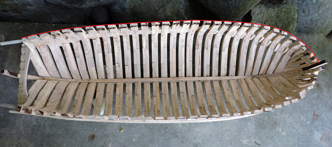
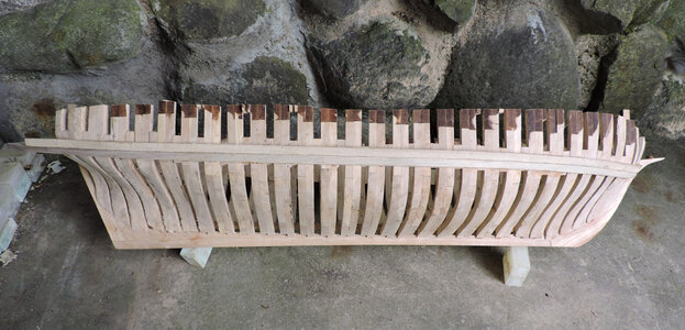
The wales stiffened the framing considerably allowing for some aggressive sanding and cutting of the bulwarks. From here on the wales will set the height of the bulwarks and deck clamps and caprail. Everything will be measured from the wales.

b1.jpg

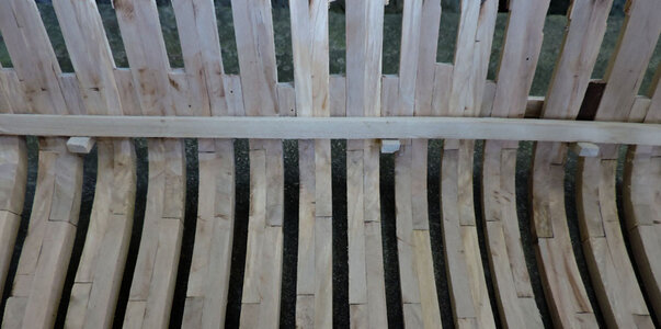
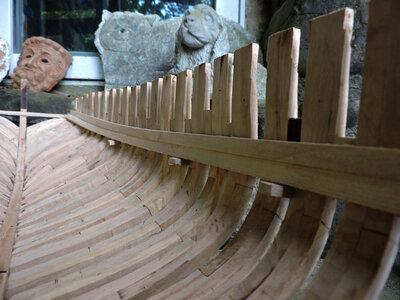
Thickness of the frames (molded dimension) right now is heavier than the final dimension because i offset the frames when i laser cut them.
You can see this at the bow and stern.

b2.jpg

b3.jpg

The idea here is to shape the upper part of the frames so you get a fair curve to the hull.
Like i said it is better to offset the laser cut or if you are cutting frames with a saw leave yourself a little extra beyond the final frame shape. If you laser cut the frames exactly on the line you have to make sure the frames are in the exact location there is no + or - leeway. Leaving extra beyond the frame line will allow you to not only a little room when building the hull but also to shape the upper part of the hull.
This step is done before you install the deck clamps which will allow you to shape the frames downward without the clamps getting in the way.

b4.jpg
 
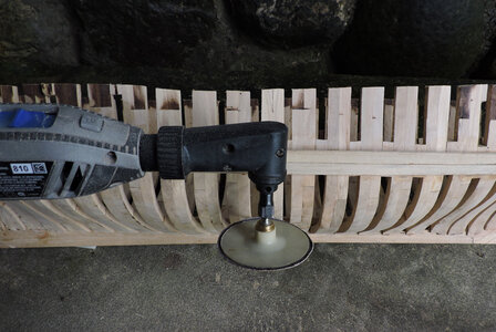
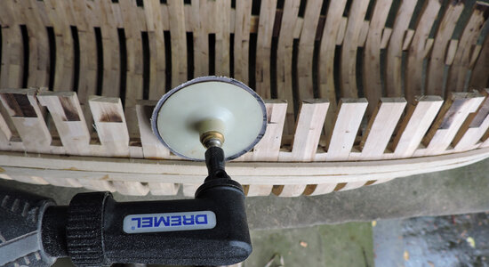
Using the 90 degree attachment to my 4300 Dremel i am sanding the outside of the bulwarks


b5.jpg

i use a disk large enough to span 3 frames because experence has taught me if the disk is to small you end up gouging frames or sanding a frame to much.

b6.jpg

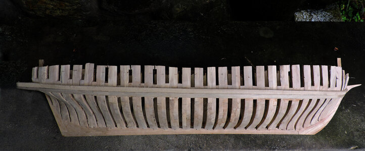
I sanded the bulkwards so all the frames fair up with one another and gives me a smoothe surface. I have not cut down the hull yet because i will wait until i put in the deck clamps and take my measurements from the clamps to the caprail line. i am leaving myself a little extra just in case the clamps slightly move up or down. If the bluwarks were planked inside and out a little miss here and there would not matter beause the planking would cover it. In the case of the Tecumseth the bulkwards are open so each and every top timber has to hit its mark.

b7.jpg
 
T372PNG.png
image credit to the Maritime Museum of the Atlantic, Halifax, Nova Scotia, a part of the Nova Scotia Museum,


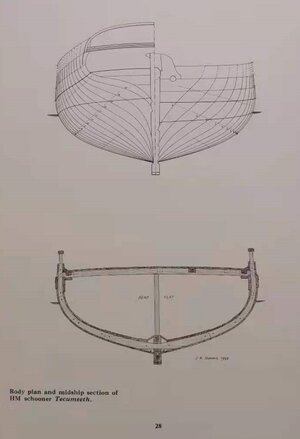
as you can see there is nothing left of the Tecumseth past the turn of the bilge so from this point on the building of the model will rely on other sources and shipwrecks for construction details.

clamp1.jpg

looking straigh down at the top of the frames you can see the wale on the outside and the deck clamp on the inside. It is called the deck clamp because the ends of the deck beams sit on the top. The timbers act more as a clamp because they clamp the top timbers between the clamp and the wales. When in place the frames become very strong and the wales and clamps add considerable longitudinal straingh and stiffness to the hull.

clamp2.jpg

the top timbers were sanded to the final thickness inside and out in doing so i lost the top of the hull so i can no longer measure down to locate the clamps.

w8.jpg

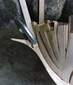
a solution was to add pieces of wood under the edge of the wales. The wales and clamps are the same height

clamp2.jpg

The pieces of wood stick through the hull so i can locate the height of the lower clamp

clamp3.jpg
 
i seems there is a delay in the progess of building the Tecumseth. Some model builders get lost if they do not have step by step how to instruction with a kit. In this case there are no instructions or detail wreck information or how to build. More time is spent finding information and then figuring out how to do something.
I actually like the challenge of figuring out how to build the model

back to the deck clamps, i am not going to just say "oh they were bent and glued to the hull" actually they were a bugger to install.

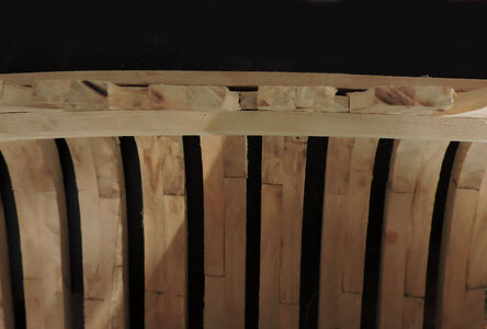
first i soaked the bow end in boiling hot water and while they were still hot i bent and clamped the piece to the inside of the bow. Then i let the wood sit there until it was dry. i did this with all 4 clamps. Then at the stern the clamp twists from vertical to horizontal so once the bow ends were bent i did the same with the stern ends. soaked clamped and let dry. It took 8 days to prep the clamps.

Once the clamps were dry they tend to spring back slightly so when i tried to bend and glue them to the inside of the hull i could not pull them tight enough to the frames without risking a break. The fun part of model ship building is the "now what?" I took a clamp resoaked it in boiling hot water for the second time and rebent them to the hull. The second bend worked a lot easier because they were pre bent so there was a lot less stress the second go around. Four day later i had the bow ends bent so i could pull them tight against the inside of the frames.

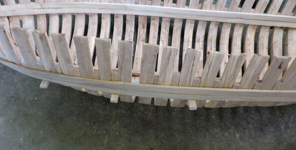
lets take a look using the sticks to locate the lower edge at mid ship the clamps fit nice to the frames and as you can see the gentile twisting curve to the stern. I only had to pre bend the stern ends only once.

clamp4.jpg

using those scrap piece between the frames insured clamps on both sides of the hull were at the same height. The lower part of the clamp took more of a twist than the upper part.

clamp5.jpg

looking towards the bow the clamps do not twist but they take a hard bend at the bow and stop at the inner side of the stem. They do take a sweep up at the bow. Glad that part is done and now i have a strong hull. i would suggest doing the wales first because bending the clamps puts a lot of stress on the frames and the frames would break before you can bend the clamps.

clamp6.jpg

It is a "best guess" situation when it came to the clamps John Stevens drew his clamps wider than the wales i made mine the same width.
My reasoning was because the clamps take such a drastic twist to the stern a wide timber would be difficult to bend and twist and still sit flat against the stern frames. So if anyone decides to built the Tecumseth you have options either John Stevens or Dave Stevens clamps. Besides the clamps will be one of those timbers that will get covered up and what's a fraction of an inch one way or the other?

js plan4.jpg
 
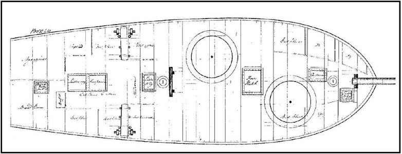
As you can see in post #114 there is nothing on the wreck to assist in the building of the deck but there is the actual deck plan.
So i know what was built but i do not know how it was built. There are questions like where the ends of the deck beams notched into the top of the clamp or notched over the clamp or both? Were deck knees used like lodging, hanging and dagger knees? I know carlings were used because they frame in the fore and aft sides of the hatches. Were ledges used?
deck of tecumseth.JPG


What does a model builder do when they run out of information?

here is my approach
Six degrees of separation is the idea that all people on average are six, or fewer, social connections away from each other.
As a result, a chain of " friend of a friend " statements can be made to connect any two people in a maximum of six steps.
It is also known as the six handshakes rule.

how does this apply? well, like any craft or artisan trade there are guilds and unions and schools and apprenticeships programs. What happens is information is taught and passed on within the industry of ship buiding. Ship carpenters and master shipwrights went from yard to yard taking the knowledge with them and spreading it about. The odds are quite hight that the shipwrights who built these ships knew one another and were familiar with the lastest ideas and who was doing what and how.

sit back and take a read about the main shipwrights of the time and place and see if you spot any similarity between them.

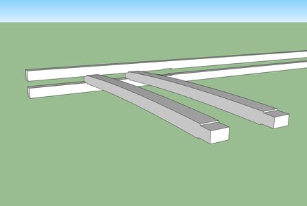
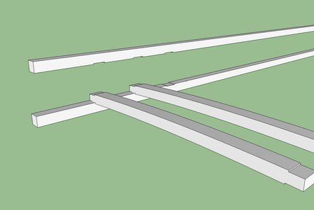
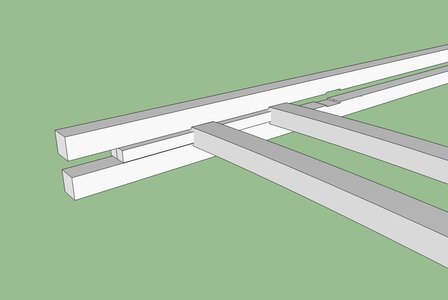
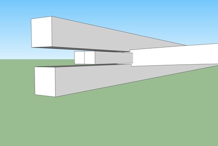
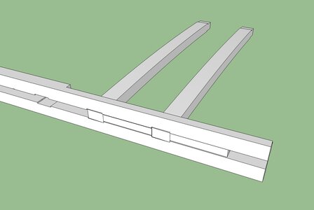
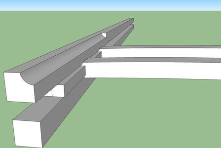
while you do the reading i will prep up a 3D model of the deck beams and deck clamp and then get back to the build.

Henry Eckford (1775–1832) was a Scottish-born Shipbuilder, Naval Architect, Industrial Engineer, and entrepreneur who worked for
the United States Navy & the Navy of the Ottoman Empire in the early 19thC. After building a national reputation in the United States
through his Shipbuilding successes during the War of 1812, he became a prominent Business & Political figure in New York City in the 1810s,
1820s, & early 1830s. Eckford was born in Kilwinning, near Irvine, on 12th March 1775, the youngest of 5 sons. As a boy, he probably
trained as a Ship’s Carpenter in the Shipyard at Irvine on the Firth of Clyde. In 1791, at the age of 16, Eckford left Scotland to begin
a 5-year Shipbuilding Apprenticeship with his mother’s brother, the noted Scottish-born Canadian Shipwright John Black, at a Shipyard on
the St Lawrence River in Lower Canada. In 1796, he moved to New York City to work as a journeyman in a Boatyard on the East River.


William Moodie Bell Naval shipwright and farmer.
William Moodie Bell (1777-1837) was the son of John Bell and his wife Ann, née Stenhouse.
He was born on 9 January and baptized on 12 January 1777 in the parish of Aberdour, near
Kirkcaldy in Fifeshire, Scotland. He entered the employ of the Provincial Marine as a naval
shipwright and began his career at Amherstburg, Upper Canada, in June 1799. There he
designed and built vessels for the Great Lakes service. Many of these were lost in 1813 at the
Battle of Lake Erie, after which he was evacuated from Amherstburg, at the time of the retreat
from the Western District, and served thereafter at the Kingston dockyard. The Admiralty's
appointment of Thomas Strickland as Master Builder in Upper Canada displaced Bell from
that position, but in 1814 he was appointed as Strickland's assistant. Upon Strickland's death
in 1815, Bell became Acting Master Builder in Upper Canada until the end of 1816, when the
establishment at Kingston was reduced and Bell returned to Scotland.
Having succeeded in obtaining a government pension, Bell returned to Canada, where he
seems to have considered going into partnership with his brother John Bell (1779-1841) and
a French Canadian shipbuilder, François Romain, at Quebec, before settling down as a farmer
at Little River, Lower Canada.


MUNN, ALEXANDER, shipbuilder and shipowner; born 26 Sept. 1766 in Irvine, Scotland, son of John Munn, shipbuilder, and Catherine Edward;
m. 6 Dec. 1797 Agnes Galloway at Quebec, Lower Canada, and they had 11 children, of whom six died in infancy; d. there 19 May 1812.

Alexander Munn is a shadowy figure. Since his personal and business records have apparently not survived, the only direct evidence
about him consists of disparate references found in routinely generated sources such as notarial records, newspaper notices, and ship
and church registers. Difficult to work, these sources do not yield a rounded portrait. But the broad picture that emerges clearly indicates
he was a leading Quebec shipbuilder in the beginning stages of that highly productive sector of the city’s economy. It is Munn’s entrepreneurial function that provides the focus in the following sketch.

Munn undoubtedly learned the “mysteries” of shipbuilding from his father before immigrating to Quebec in or before May 1793. In the 1790s
the establishment of big-ship construction in the city implied a transfer of skills and capital in person from Britain. Certainly the cumulative evidence about British American shipbuilding in general shows a heavy reliance on Britain for technology (in the wide sense of the term), capital, and markets; the emergence of a native-born shipbuilder before about 1830 is rare.

Munn first appears in Quebec records in February 1794 when he described himself as a “ship carpenter” in a notarial act; by 1803, however,
he was calling himself a “shipbuilder.” These descriptions superficially suggest that he rose from journeyman to master craftsman within
the craft hierarchy, but in shipbuilding at Quebec at the turn of the 19th century the craft system seems to have been a vestigial formality
which bore little weight in the actual economy of shipyards. Apprenticeships, which were common, were clearly used by employing shipbuilders
primarily as a legal device to circumvent labour shortages, and the status of master shipbuilder did not entail any special political
privilege as it did at Saint John, N.B., where it carried with it admission to the freedom of the city.
The change in Munn’s title is more likely explained by what appears to have been a well-observed unwritten rule reserving the use of
the appellation of shipbuilder to those who operated substantial yards, as Munn did by the later date.

Beginning in the mid 1790s, at premises leased from the firm of Johnston and Purss [see James Johnston*] on the King’s Wharf in Lower Town,
and after 1806 as proprietor of an extensive shipyard at Anse des Mères, Munn frequently launched two large vessels a year, one in the
spring and the other in the fall. In addition, a certain amount of repair work seems to have been turned out from his yards. A conservative
estimate of his new production, based mainly on the certificates of ship registry, would be 17 vessels having an aggregate of 4,470 tons,
built between 1798 and 1812 inclusive. The actual launchings may have exceeded these figures considerably since certificates do not always
fully identify builders and no other satisfactory source exists. As with the bulk of the tonnage built in British America in the century
after the American revolution, Munn’s ships and brigs were constructed for the British market. His known production indicates that he built
primarily on his own account, or under contract with a British agent, an example of the latter arrangement being an 1807 agreement with
ohn Drysdale for construction of a 435-ton ship. Since contract building appears to have involved a flow of capital from the future owner
to the builder at specified periods during construction, Munn’s registration of ten vessels in his own name testifies to his strong financial
position; he possessed, or had access to, sufficient capital to avoid the dependence usually imposed by contract construction. The source of the capital with which he established operations is unknown; presumably he drew from his family network, but it seems a safe assumption that much of the subsequent finance was generated from sales.

Alexander was one of at least five contemporary shipbuilding Munns, four of whom established themselves in Lower Canada and were probably
of the same family. The fifth, Alexander’s brother, James, was a shipbuilder at Troon, Scotland, in 1800 when, following the death of their
father, Alexander gave him power of attorney to look after his shipping interests in Scotland. He may have been the same James Munn,
shipbuilder, located at Irvine in 1803 and mentioned in the correspondence of John Scott and Sons, a shipbuilding firm of Greenock, Scotland,
and Saint John, N.B.; he was one of the first steamship builders on the Clyde. A John Munn, who may have been Alexander’s brother, began building at Quebec as early as the fall of 1797, and within a few years he had brought his young son John* into partnership to run a shipyard in the faubourg Saint-Roch, the area of the port, bordering the Rivière Saint-Charles, which later in the century was to have the largest concentration of shipbuilding in British America. David Munn, who may also have been Alexander’s brother, operated a shipyard next to Molson’s Brewery in the Montreal suburb of Sainte-Marie from 1805 to about 1820, and much of his construction may have been financed by the Greenock merchant Robert Hunter, with whom he registered 14 of 17 vessels, totalling 4,916 tons. David also had business interests at Quebec; in 1812 he guaranteed the performance of John Munn and Son in a contract to build a ship for a London merchant. The same year he was one of two shipbuilders who valued the vessels in Alexander’s estate, and two years later he rented Alexander’s shipyard from the latter’s widow.

Given the paucity of evidence, it is difficult to trace in detail the operations of the early colonial shipyards and the social formations which developed from them, not least in the instance of Alexander Munn. Nevertheless, the general outline is sufficiently clear to allow assertion that the shipyard represented a vanguard stage in colonial productive enterprise in terms of unit size, division of labour, rhythm of employment, control of materials, labour discipline, and capital requirements. Similarly, shipbuilders may be seen as a new class of entrepreneurs in the colonial setting, a variety of manufacturer as different from the contemporary master artisan as from the industrial capitalist who followed him. If only broad generalizations can be made about the work and financial structures of Munn’s shipyard operation – principally from the size of vessels constructed (of those registered, between 119 arid 469 tons) – there are a few precise indications of his own economic and social status. The rents for his shipyard site at the King’s Wharf amounted to nearly £400 annually by about 1800, and in 1806 he paid the bankrupt estate of the London
shipbuilders William and John Beatson £3,050 for the shipyard at Anse des Mères. In 1812 an inventory of his movable property
(but not of the land, buildings, or cash) indicated that effects in his “Yard & Stores” were worth £1,055; as well, a sloop afloat was valued
at £300, a new brig, the James, at £2,700, and a new ship on the blocks, the Diana, at £4,000. In his marriage agreement in 1797
Alexander promised Agnes £300 on his death. His estate, for which she was administratrix, did indeed leave her well established.
She lived on in a newly built, substantial stone house, employing a manservant for at least one year at a salary of £20. The shipyard was
subsequently leased on an annual basis to various individuals, including David and John Munn, and finally sold in 1839 to James Bell Forsyth*
for £6,250.

Munn’s only evident sally into a public position took place around 1807 when he became acting surveying officer of the port. Certainly he was
a privileged member of Quebec society, enjoying advantages that clearly stemmed from being a shipbuilder. In addition to trips to Britain,
there are signs of gracious living in the inventory of his estate: two calèches and three carrioles; a lady’s side-saddle; and a piano. Also,
for the education of the children, Munn had employed a tutor who lived in. These luxuries were beyond the reach of his employees;
one of his apprentices, for example, was engaged in 1807 for but £8 per year plus meat, drink, and lodging. There can be little doubt that
they were also beyond the resources of master craftsmen, then the typical entrepreneurs of production outside shipbuilding in the
pre-industrial economy of British America.
 
The point of the last post was to show these shipwrights knew each other and had neighboring shipyards, even worked at the same yards.


Adam and Noah Brown were brothers from upper New York State. Noah Brown was apprenticed as a carpenter from 1785 to 1792, and worked in New York until 1804, when he and his brother Adam built the schooner Work at Newark, Upper Canada, (now Niagara-on-the-Lake, Southern Ontario) for the
North West Company. In early 1805, the brothers built a whaler at Sag Harbor on Long Island
During the War of 1812 they constructed the privateers General Armstrong, Paul Jones, Prince de Neufchatel, Warrior, Yorktown, and Zebra at
New York and were then contracted to construct military vessels for the U.S. Navy. Under the general supervision of Henry Eckford,

From varoius shipwrecks and historical data ships built on the lakes durning the war of 1812 were using a different construction methos which did not use knees in the deck construction. Even though british ships back in England did use knees here in North America shipwrights and carpenters were Scottish and American.

When the Brown brothers built the Eagle on Lake Champlain this is the method they used. The deck beams were not notched to fit over the clamp

brown beams3.jpg

To replace the deck knees the clamp and waterway were increased in size almost to the dimensions of a keel. These large over size timbers were bolted to the inside face of the frames. Then the ends of the deack beams were set into notches cut along the top of the clamp. The waterways were notched to fit over the deck beams. a one inch iron pin was driven through the waterway, deck beam and into the clamp, locking in the beam and clamping the end in between the heavy timbers.

brown beams2.jpg
brown beams1.jpg

Thr British did have spies peeking in on American Shipyards and the shipwrights knowing one another and their construction methods the kneeless system was adapted in the British yards at Kingston and Amhersburg as well as yards on Lake Champlain.
It was a well know fact the use of knees produced a strong hull and deck, however the cost to obtain knees and the time to shape and fit them were time consuming. These ships were built to serve a short period and the timbers would rot before a ship fell apart due to lack of knees.

next we will look at the construction of the Jefferson built by Henry Eckford
 
Now lets take a look at the Jefferson built by Henry Eckford, it is the same concept as Noah Brown did by clamping the ends of the deck beams between two heavy timbers. One difference is Brown did not cut notches in the ends of the beams but Eckfors did. sizes of the beams, clamps and waterways are very close to the same size used by both shipwrights.

eckford beams3.jpg

eckford beams1.jpg

One thing Eckford did different was to add 6 x 6 filler timbers between the beams

eckford beams4.jpg

looking at an end view the first 6 x 6 was spiked to the inside of the frame and the second 6 x 6 was spiked to the first 6 x 6. Notice when these were installed a space was left at the top and bottom.

eckford beams5.jpg

from the end view it looks like these fillier pieces are floating but when viewed from the back you can see the deck beams, waterway, clamp and filler piece are all even and would be resting against the inside face of the frames.

eckford beams7.jpg

i can only venture a guess for the filler pieces between the deck beams. They are below the top surface of the beams so they would not aid in supporting the edge of the deck planking. The space at the top and bottom would serve as to allow air movement. The only reason i can come up with is to make sure the deck beams do not move or twist out of their notches.

eckford beams6.jpg
 
there are lodging knees and hanging knees and also dagger knees so lets explore the dagger knee

i am going out on a limb and not fact check but rely on memory. I read at some point someplace the American fleet on lake Erie for the war of 1812 the construction of the ships were actually started by Daniel Dobbins and his crew later Noah Brown and his carpenters came from New York and finished the job. Then along came Henery Eckford to inspect the ships and gave a thumbs up.
So looking at the wreck of the Niagara it is clear dagger knees were used, the question is did Dobbins include them or did Noah Brown install them. When Brown built the Eagle there were no knees of any sort, so i am inclined to think the dagger knees in the Niagara were Dobbins doing and not Brown's.

niagara2.JPG

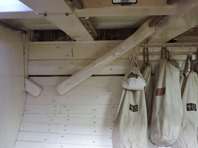
when a reconstruction of the Niagara was built dagger knees were also used

DSCN6935.JPG

in this photo you can see the frames between the deck beams and the inside of the hull planking. It is this space Eckford filled in with 6X6 timber. So it is possible the 6x6 timbers were replacing the dagger knees.
is it possible lodging knees, dagger knees and filler timbers were used to prevent the deck beams from racking fore and aft?
 
Last edited:
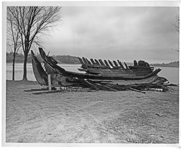
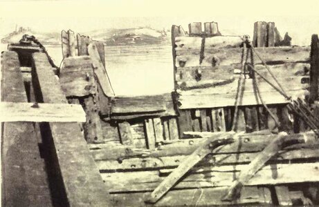
there is little evidence on deck construction or the construction of anything above the turn of the bilge from shipwrecks. Back before marine archeology and the meticulous study of the wreck these old wrecks were ripped from the lake bed with clam shell cranes, chains were wraped around sections and the hulks were pulled apart. Same fate of the Niagara. There are photographs of the brutial salvaging of these wrecks and some data can be gleaned from the images if you can get your hands on the original photographs.
niagara3.JPGniagara1.JPG
 
Back
Top