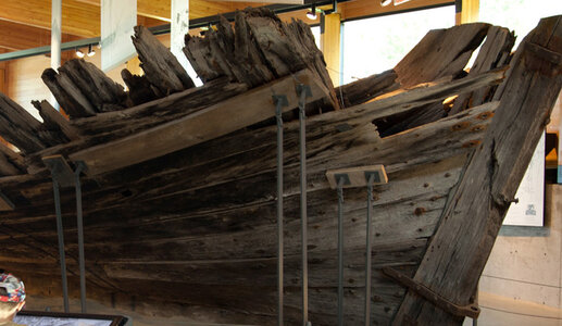
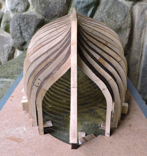
Tecumseth 1815

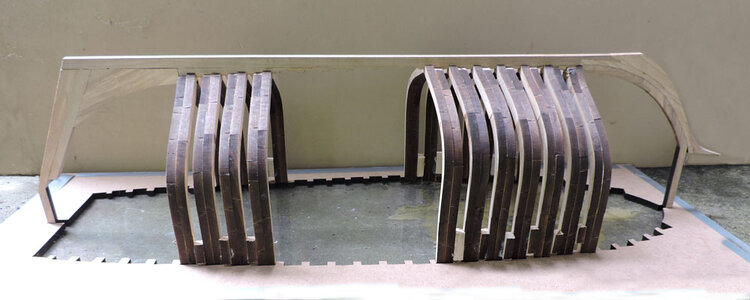
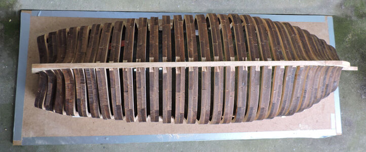
With the first and last full frames in place it is just a matter of adding frames.

jig6.jpg

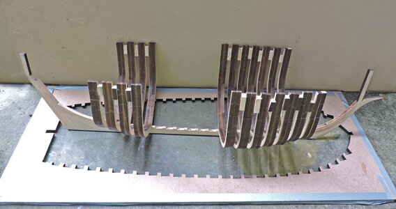
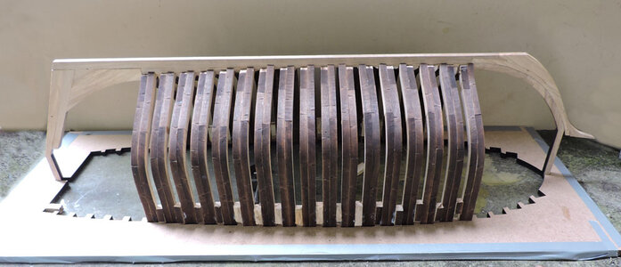
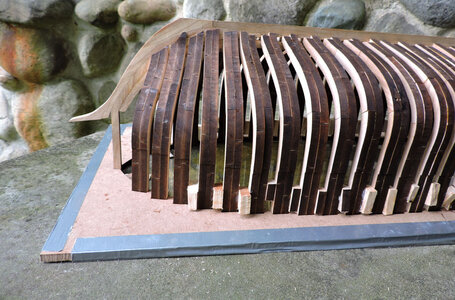
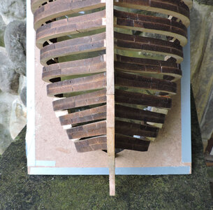
the frames are glued together with spacer blocks but the frames are not glued into the jig. I am able to remove the hull at any time.

jig7.jpg

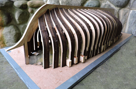
I can inspect the hull inside and out to make sure the frames are lining up correctly

jig8.jpg

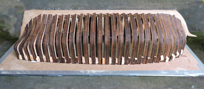
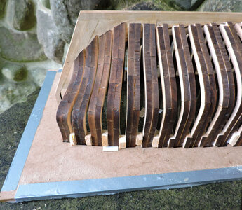
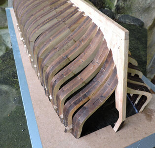
it did not take long to install all the whole frames

jig9.jpg

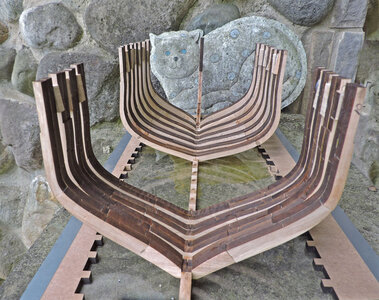
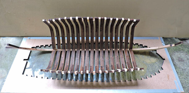
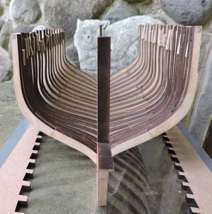
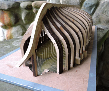
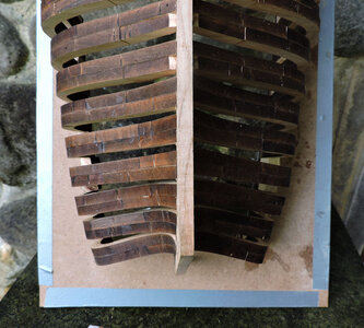
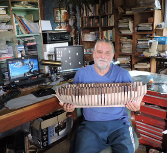
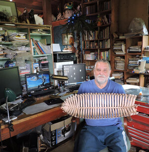
i poped it out of the jig to inspect the framing

jig10.jpg

and took a look down the inside to make sure no frame is out of alignment

jig11.jpg
 
before moving on to the next step a few ideas on building a framed hull.

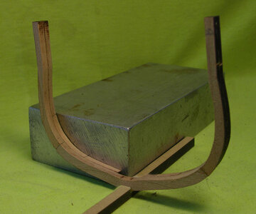
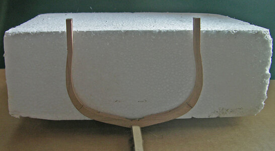
Framing a hull with or without using a jig the goal is keeping the frames square and perpendicular to the keel. This can be done with a square block or use a vertical surface against the frame.

block frame.jpg
foam frame.jpg

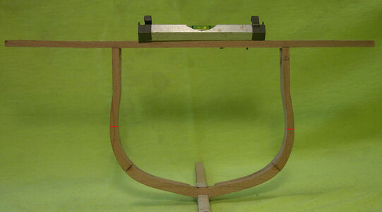
a line level is useful to keep the frames level from side to side

level frame.jpg

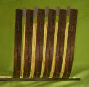
using spacer blocks prevents the frames from leaning

leaning frame.jpg

however using spacer blocks does not guarantee the frames are perpendicular. Each frame may be + or - a few thousands as well as the blocks. This small measurement starts to add up after a few frames.

spacer slant.jpg

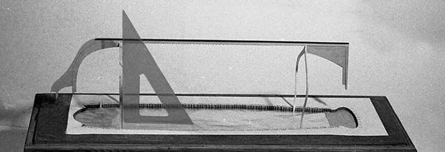
To avoid frames from leaning make sure the frame is square to the base

squareup.jpg

As i built the Tecumseth i would view the framing down the hull inside and out to make sure all the frames are lining up. Here you can see the frames are uneven and leaning from side to side.

tilt frame side.jpg

it was not uncomon for shipwrights to fill in the hull above the wales as a solid wall of timber. Leaving filler blocks in the hull makes a strong hull and the blocks will be covered by planking inside and out.

spaced frames.jpg
 
moving on to shaping the hull.

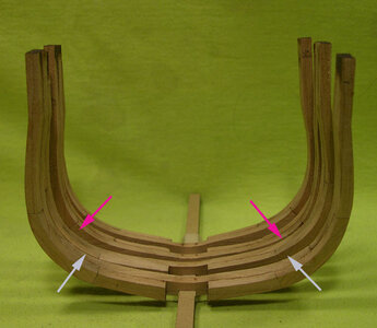
There are two schools on this step of hull construction one i will refer to as the PT method because that is where i saw it used. I met Portia Takakjian several times and sat and talked to her at a few NRG conferences. Harold Hahn and Robert Bruckshaw were both formal trained draftsmen and they were able to accurately draw frames and parts, Portia was not and her drawing were crude which makes one wonder how she managed to get such a perfect shaped hull from such rough drawings. Years ago i was working with a group doing claymation, I had a grasp on blocking out figures and objects and sculpting details. That is exactly what Portia was doing, she said you don't have to draw out all the frames just use the bodyplan and shape out every 3rd or so frame, then fill in between these "control frames" with blocked out frame blanks, you do not ever have to be close to a final shape. Then sand or sculpt the hull shape from the rough form.

The second method was held by an elite self proclaimed group who insisted they are preserving the art of ship building and model ship building must follow the correct methods of building. A ship real or a model is built from the keel up and not some upside down method or sculpting a hull from rough frame blanks. Each and every frame shape is lifted from the hull lines and built to the finished shape and then set on the keel. OK that means you have to have absolute perfect drawings of all the frames to start with, and that is so much easier said than done.

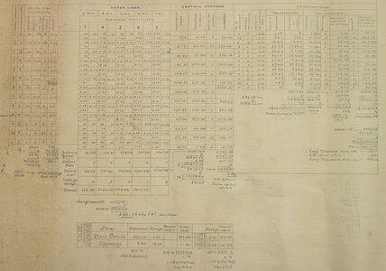
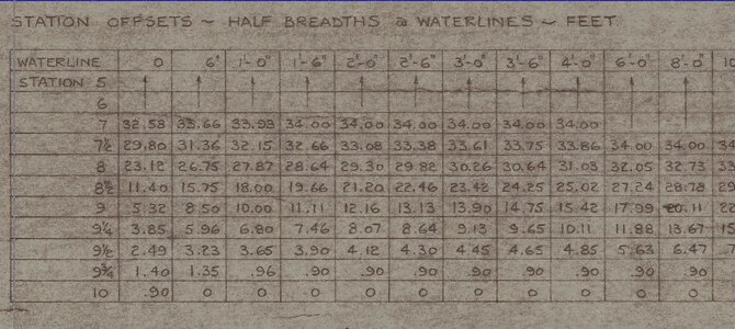
As time went on and the internet became available more information was learned about how hulls were framed. Portia was closer to the truth than the ones who insisted on drawing all the frames. Actually a 1/2 hull was carved "sculpted" then a series of offsets were done. These tables of offsets were used on the mold loft floor to draw out the frames full size. Hull were built by the numbers, but not perfect, again Portia's idea of carving the hull to shape was actually done within limits it was refered to as "dubbing" once a frame was erected skilled craftsmen went in and gave the frames a final shaping.

offsets.jpgPIERSON OFFSET2.JPGPIERSON OFFSET5.JPG

The Tecumseth is a hybrid of all of the above to achieve a final result.
 
Before i get into shaping the hull i skipped a step in building and that is adding the keelson. You have to add the keelson because the half frames at the bow and stern sit against the side of the forward and aft sections.

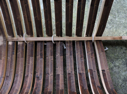
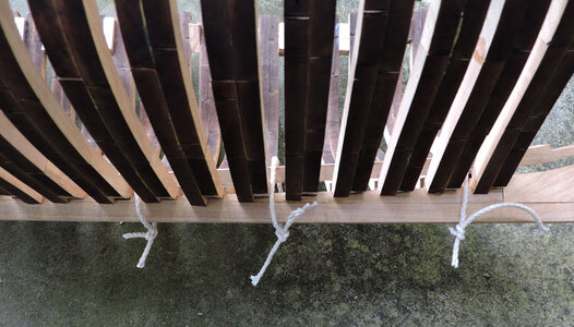
first i cleaned off the char on the top of the floors, set the keelson on top of the floors and tied a string around the keelson and down around the keel.

keelson1.jpg

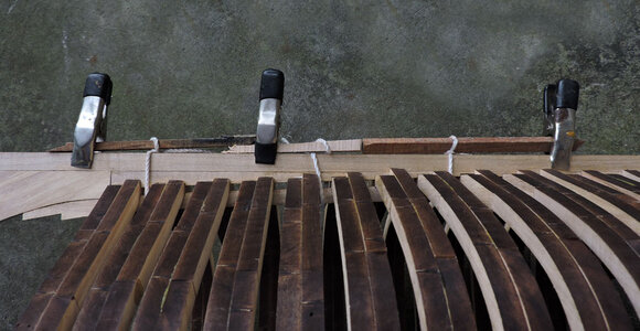
There is no way to get a clamp on the keelson and keel so i am using a tourniquet

keelson2.jpg

inset a piece of wood between the keel and string and tun it until the keelson is tight against the floor timber, then use a clamp to stop the string from unwinding.

keelson3.jpg

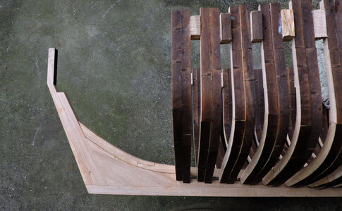
now add the last pieces at the stern and bow deadwoods.

keelson4.jpg

keelson5.jpg
 
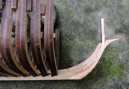
I did not photograph in detail installing the half frames 11 to 16 they are pretty much straight forward, they are built like the whole frames in 2 overlapping parts. you do not have to build them to the jig, just line up the edges. Installing the half frames is simple the top fits the jig notch and the foot sits against the deadwood. The angle of the frames are on the drawings.


stern frames.JPG

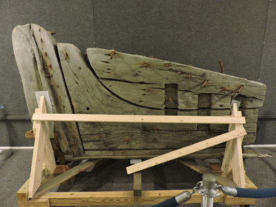
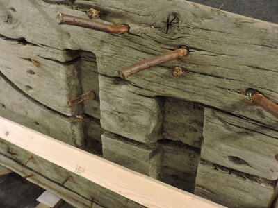
One unknown detail at this time is how the frames are attached to the deadwood. There are examples of the foot of the frames sitting in a box cut into the deadwood like this example.

box1.jpgbox2.jpg

The probem with the Tecumseth is the fact there is planking covering the deadwood so someone has to look down into the hull to see if the foot of the frames sit in a box cut into the deadwood. Or maybe at some point when the wreck was examined someone might of recorded the information.

stern.jpg

For the prototype build the frames are sitting against the deadwood. Right now the foot of the frames are random, as the hull is shaped the foot of the frames will be finished to match the rising line in the drawing.

stern frames1.jpg

stern frames2.jpg
 
the bow and stern cant frames are done the same way

using the drawing i made a cardboard template for the angle each frames sits against the deadwood

bow drawing.JPG

cant1.jpg

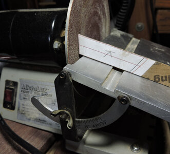
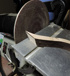
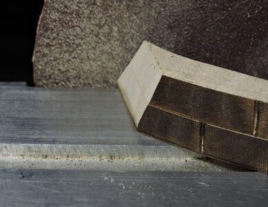
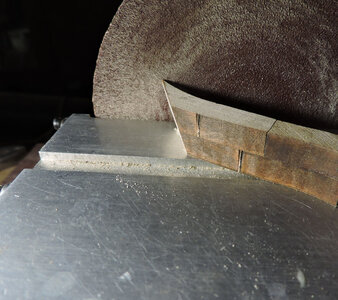
setting the disk sander i sand the foot of the frames watching the the edge so i can sand it even and right to the edge without going to far.

cant2.jpg

finishing the angle

cant3.jpgcant4.jpg

at this point of construction i am stopping with frame K and i will install the bow timbers later.
 
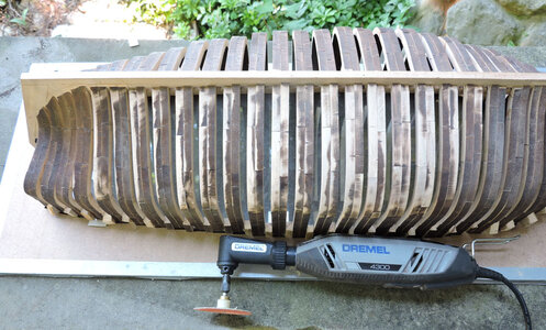
now for the sanding, i used a Dremel tool with homemade sanding disks. The disks are made from plastic bottle tops and jars. A word on the Dremel tool, there are different models available and when you use them for something like sanding the Tecumseth hull they get hot. I have burned out more that one tool in the past. The 4000 series are a bit more heavy duty and do not get as hot as quickly as the smaller hobby size models. Another point is if you are using a disk for sanding make sure the size of the disk covers 2 frames or you may end up gouging a frame and by covering 2 frames at once you are using the frame surfaces to blend one frame into another. I also used a small palm sander for the final sanding.
One that looked like this one, there is a big difference between "hobby" tools and mini tools used for crafts The hobby tools are for the most part under powered or grossly over priced.

sander.JPG

starting at the center at the bottom of the hull
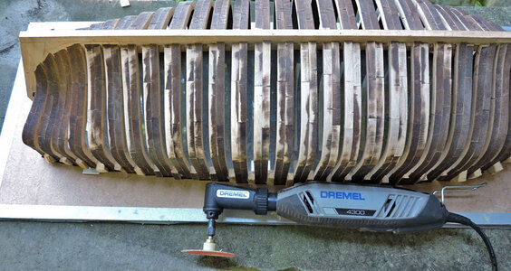
sand1.jpg

i am sanding to the bow and stern, the laser char is quite helpful because it is showing the low spots
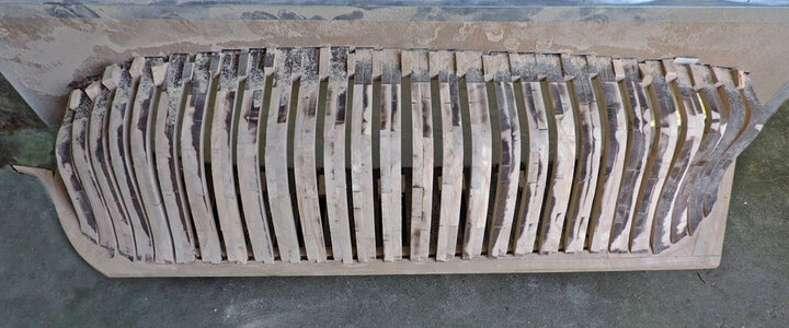
sand2.jpg

as i reach to stern you can see the bevels are starting to form as the sander is hitting the back side of the frame faces. This is why i did not bother sanding the bevels before installing the frames. Sanding the hull will create the bevels and they will tend to blend into one another.
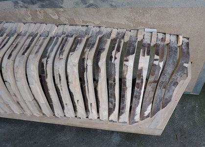
sand3.jpg

the same thing is going on at the bow the front of each frame forms the bevel from frame to frame.
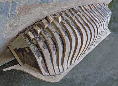
sand4.jpg

the more you sand at the stern the more the hull shape is formed and the bevel is hitting all the way back to the last frame.
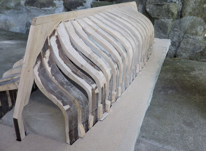
sand5.jpg

At the bow on the right side you see how the frames step down, on the left the sanding in of the bevels blends the frames into one another.
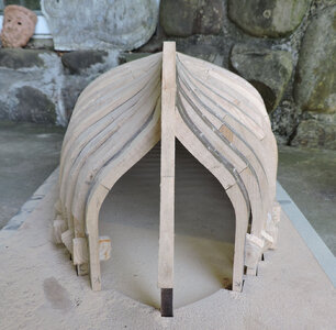
sand7.jpg

Working the length of the hull all the char is gone except for a couple low spots that will be sanded out with the final sanding. Here you now see where that notch at the top of the frames come into view. That notch is at the sheer line and defines the top of the hull. The extra wood above the notch comes in handy when you cut the hull down and create a smooth curved sheer line. If you did not have that extra wood above the sheer line every frame has to be exact or a frame might fall short of the sheer. Most of the time that will not matter because a cap rail and planking will cover the top of the frames.
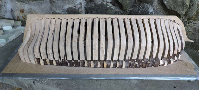
sand8.jpg

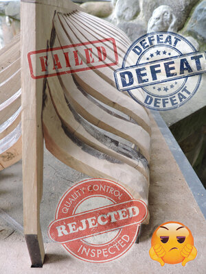
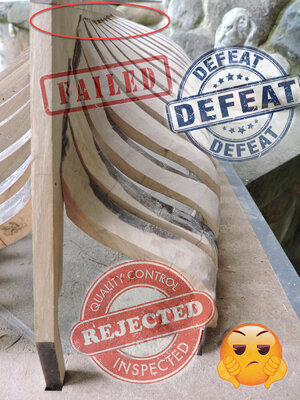
Then this happens!
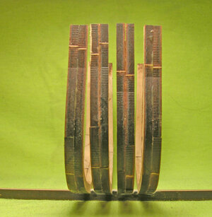
reject.jpg
 
Last edited:
I think this is why (red circled)
View attachment 247002
Hello Dave, You have a very interesting build here that you are just flying along at a very great speed and that is for sure. One hast to expect these little Boo-Boob's to pop up every now and thin, they just make things a bit more interesting. I am sure that this will not set you back very far and that the rebuild will surely be better than the first.
Regards Lawrence
 
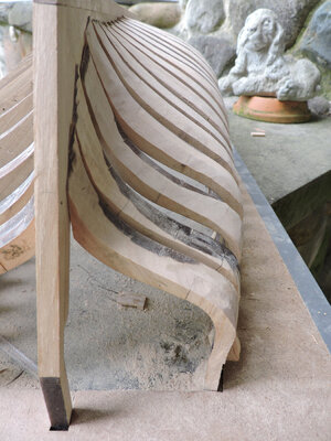
Jimsky that is not the problem that is an illusion because the frames rise as they approach the stern. Because you are viewing the bottom of the hull upside down at the level of the red arrow you see the frames rising , then the foot of the last frames are not sanded to the rising line making the frames look like they take a dip.

rising view.jpg

rising.JPG


Why are you saying the model has failed Dave ? I thought you were progressing with it O.K.

i was moving along just fine on the prototype it is not a total fail and it can be salvaged.


Hello Dave, You have a very interesting build here that you are just flying along at a very great speed and that is for sure. One hast to expect these little Boo-Boob's to pop up every now and thin, they just make things a bit more interesting. I am sure that this will not set you back very far and that the rebuild will surely be better than the first.

Boo Boob's were expected as a matter of fact i saw this coming a mile away but continued just to see what would happen.
 
here is the thing

when anyone reads build logs 100% of the time they show case the work of a builder. You get "nice job", "well done" "looks great" etc and these inspire others to take on a build.
How many times does a builder show off an epic fail? i say never! what kind of comments can you expect "nice fail dumb ass"
"boy you screwed that up", "holy smokes dude really?"

i see it as look at this mess and here is how i fixed it.
 
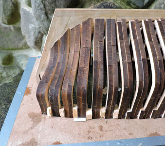
Back when i was sanding the hull i mentioned using the laser char to show low areas in the hull. The char that is left on the last 3 frames is as far as i can shape the hull

sand6.jpg

i ripped out frame 14 to take a look.

DSCN3293.JPG

the problem is looking at the frame to the left it got way to thin at the bevel if i were to keep sanding the hull to remove the low area of the char to the right the green line would actually sand away the frame before it reached the proper shape. One frame effects the other frames before and after the bad frame.

fr1.jpg

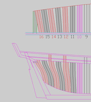
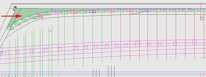
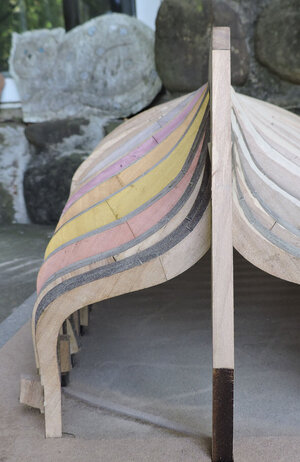
i saw this when i built the hull the space between the yellow tinted frame and the pink tinted frame was way to much and the pink frame and the second last frame was also not right. Actually you can follow the frame shapes all the way back to frame 9 that is sticking out. The error at that point between 9 and 10 was slight but it was that creeping error that just got worse as it went back.

fr2.jpg

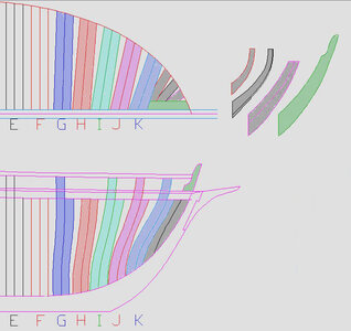
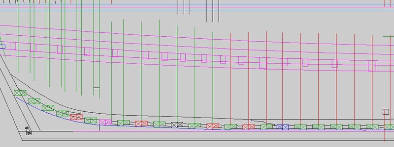
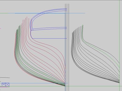
back tracking all the way to the original drawing starting at the green and black frames there is a black frame kind of standing out that is frame 9 and where the error started. There is to much space between 9 and 8, frames 10, 11, and 12 the spacing is close then a wide space between the next 3 frames. This error showed up durning the 3d modeling but it was corrected in the 3D model.
So i knew this was a concern i just kept going just to see what would happen and i found out.

drawing.JPG

i could have kept sanding and shaping the hull until the last char areas were gone but that would cause the error to creep forward because all the other frames would be sanded far to thin.

thanks to the guys who taught me this art also taught me not only do you have to teach yourself how to design, draw and build a ship model you also have to know how to take them apart, fix and back engineer them.
 
Last edited:
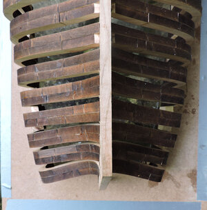
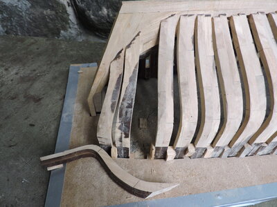
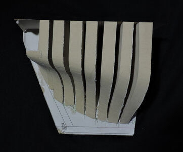
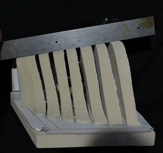
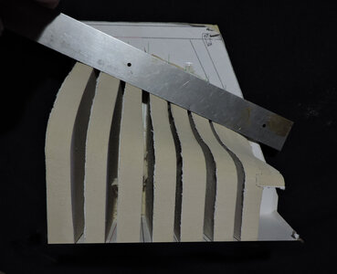
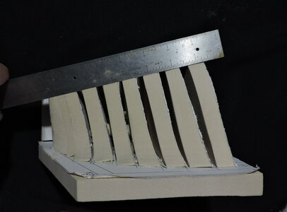
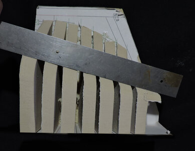
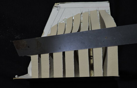
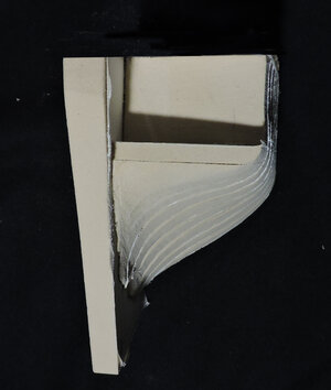
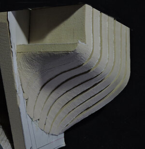
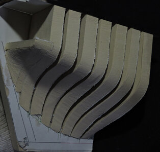
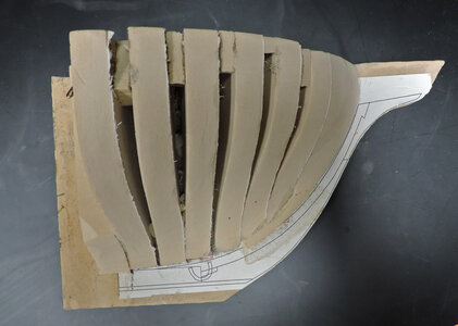
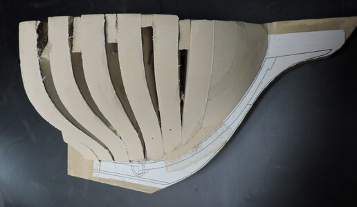
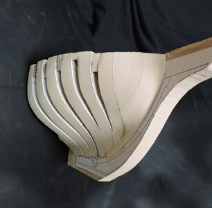
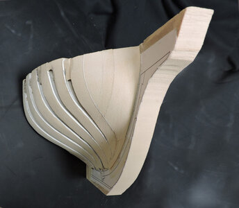
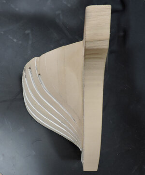
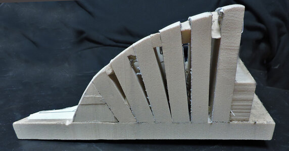
first thing i did was redraw the body lines from frame 10 to 16 then i took the new frame shapes and built a foam board mockup of the stern. Shaping the stern and using a straight edge to make sure each frame and it's bevel flowed from one frame to another.

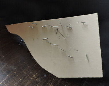
the last 3 images show the new shape of the stern and how it should look which is a continuous smooth surface. I did not attempt to draw the bevels what i did do was slip a piece of thin card board between each frame in the mockup forward edge and the beveled edge the scanned the tracing and redrew the frame shape and bevel line.stern mockup1.jpgstern mockup2.jpgstern mockup3.jpgstern mockup4.jpgstern mockup5.jpgstern mockup6.jpgstern mockup7.jpgstern mockup8.jpgstern mockup9.jpg
 
Back
Top