This is really amazing Dave. Your talent and abilities with CAD and building out the Model from research is mind-blowing to me.
-

Win a Free Custom Engraved Brass Coin!!!
As a way to introduce our brass coins to the community, we will raffle off a free coin during the month of August. Follow link ABOVE for instructions for entering.
-

PRE-ORDER SHIPS IN SCALE TODAY!
The beloved Ships in Scale Magazine is back and charting a new course for 2026!
Discover new skills, new techniques, and new inspirations in every issue.
NOTE THAT OUR FIRST ISSUE WILL BE JAN/FEB 2026
You are using an out of date browser. It may not display this or other websites correctly.
You should upgrade or use an alternative browser.
You should upgrade or use an alternative browser.
Tecumseth 1815
- Thread starter Dave Stevens (Lumberyard)
- Start date
- Watchers 17
-
- Tags
- tecumseth
- Joined
- Dec 1, 2016
- Messages
- 6,383
- Points
- 728

This is really amazing Dave. Your talent and abilities with CAD and building out the Model from research is mind-blowing to me.
Thank you Donnie
- Joined
- Dec 1, 2016
- Messages
- 6,383
- Points
- 728

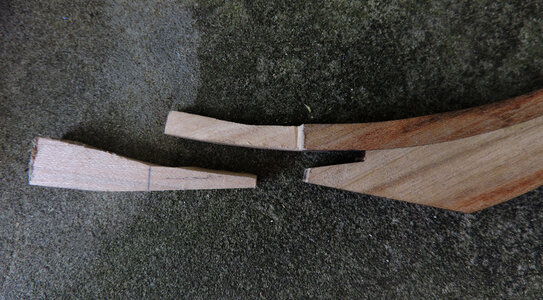
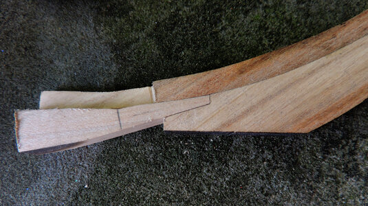
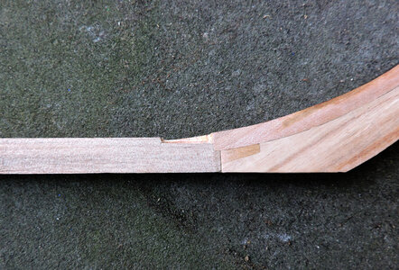
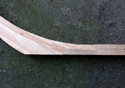
fixing the gap
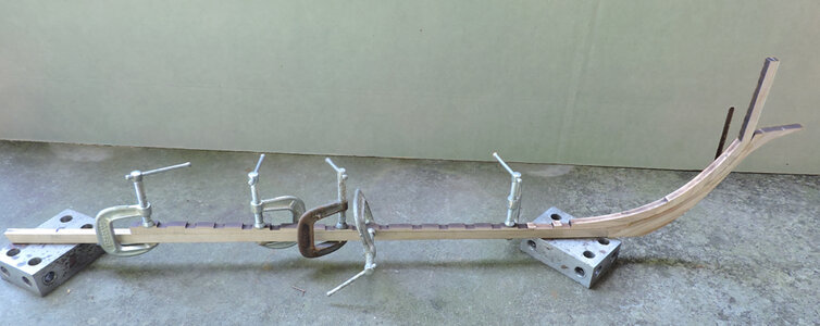
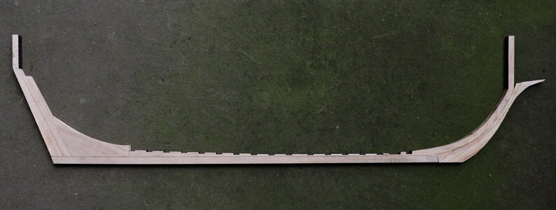
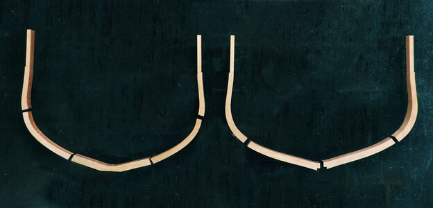
i started by gluing the gripe to the apron and tight to the knee
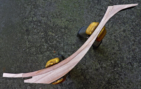
as a note: when you use lighter colored wood the joinery will be pronounced much more as opposed to using a darker wood where the joinery will not be as noticeable.
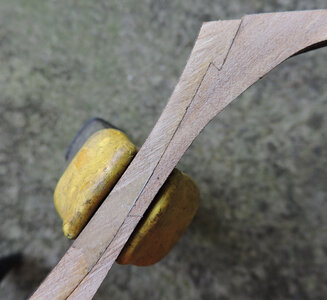
to close the gap you need to adjust the end of the apron where it fits into the notch
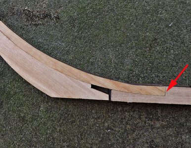
then you have to flip the parts over and adjust either the end of the keel or the apron. I would not attempt to make these adjustments with any power tool like a disk sander or Dremel tool because the adjustment it so slight it is easy to sand to much. I used a piece of sandpaper glued to a flat stick. It is fussy and you have to sand a little at both joints until the stem and keel come together.
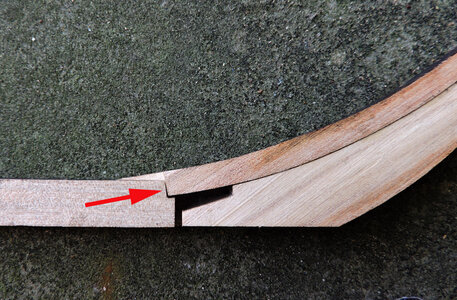
i started by gluing the gripe to the apron and tight to the knee

as a note: when you use lighter colored wood the joinery will be pronounced much more as opposed to using a darker wood where the joinery will not be as noticeable.

to close the gap you need to adjust the end of the apron where it fits into the notch

then you have to flip the parts over and adjust either the end of the keel or the apron. I would not attempt to make these adjustments with any power tool like a disk sander or Dremel tool because the adjustment it so slight it is easy to sand to much. I used a piece of sandpaper glued to a flat stick. It is fussy and you have to sand a little at both joints until the stem and keel come together.

- Joined
- Dec 1, 2016
- Messages
- 6,383
- Points
- 728

- Joined
- Dec 1, 2016
- Messages
- 6,383
- Points
- 728

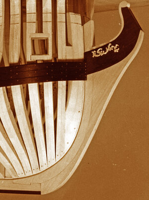
there is a second wedge that goes in the blue area.
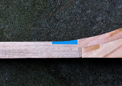
much of the joinery being done will be coved up and not seen in the finished model. You will see the lower wedge but not the top one.
There is a simpler way of building and that is to make the stem either in one piece or just a couple pieces. I do not think the elimination of unseen detail lowers the value of the model. Harold Hahn went with the simplification of various parts in his models. He was and his models are still criticized for his simplier construction and leaving out details. All i can say to those critics how many models did you sell for $36,000.00?
If the Tecumseth is picked up by a model kit company and the keel and the 2 pieces of the rising wood were designed as one piece and the stem was redesigned as one piece for a hobby kit that might be a good idea. Even to replace all the frames with bulkheads. In the end you still have a model of the Tecumseth not as built but what it looked like.

- Joined
- Dec 1, 2016
- Messages
- 6,383
- Points
- 728

the two wedges are in and moving on to the next pieces
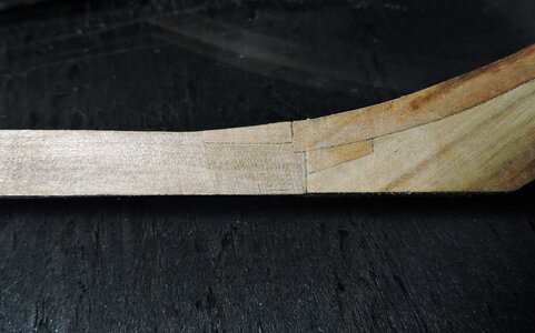
adding deadwood i first joined the two pieces
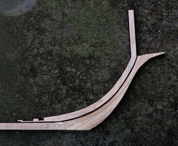
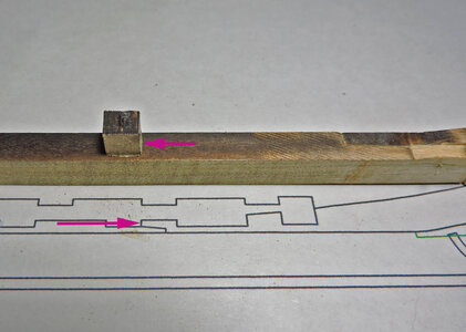
lining up the parts on the drawing, it is easy to slip the parts up or down along the curved apron. It is important the deadwood and rising wood pieces are in the exact location and the sides of the the notches line up at the arrows. A little work is need to fit the pieces against the apron.
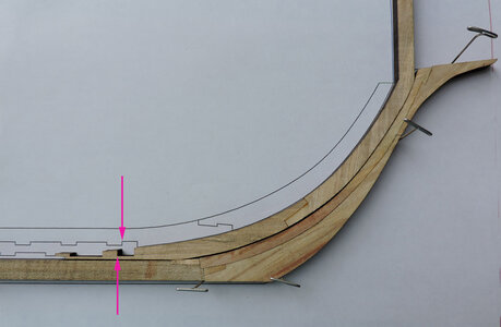
a block was glued on the keel to locate the end of the rising wood.
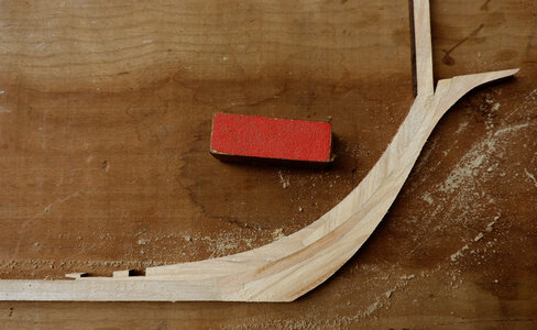
A little light sanding and the stem is finished

adding deadwood i first joined the two pieces

lining up the parts on the drawing, it is easy to slip the parts up or down along the curved apron. It is important the deadwood and rising wood pieces are in the exact location and the sides of the the notches line up at the arrows. A little work is need to fit the pieces against the apron.

a block was glued on the keel to locate the end of the rising wood.

A little light sanding and the stem is finished

- Joined
- Dec 1, 2016
- Messages
- 6,383
- Points
- 728

- Joined
- Dec 1, 2016
- Messages
- 6,383
- Points
- 728

the next part of this project is the setup and the framing.
This is the main reason few builders attempt a plank on frame scratch built project, drawing out the framing then building the frames piece by piece.
i am in a debate with myself as to how to proceed from here.
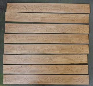
the simple answer is you draw the frames, break them apart and nest them on sheets for laser cutting Once again you have to do the CAD work in the scale of the model you intend on building because you can not do a sheet layout full size and scale it down, it does not scale in proportion. Once again 3 1/2 x 32 inch sheets.
then you build each frame and you end up with a hull like this
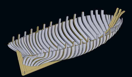
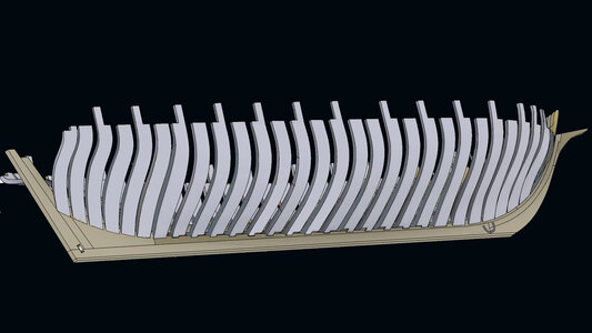
How i got to this point is a topic in itself and i realize most all builders on the forum build plank on bulkhead kits so drawing frames is of no interest to a majority of the builders. boring!
maybe just skip over the CAD and jump into the frame building?
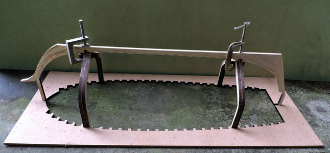
Why is a jig above the hull and the hull not sitting in a jig?
to be honest it took me 3 tries before i had a framed hull i was satified with. Not that i built three hull but i did rip out frames, redrew them and replace sections i did not like.
This is the main reason few builders attempt a plank on frame scratch built project, drawing out the framing then building the frames piece by piece.
i am in a debate with myself as to how to proceed from here.

the simple answer is you draw the frames, break them apart and nest them on sheets for laser cutting Once again you have to do the CAD work in the scale of the model you intend on building because you can not do a sheet layout full size and scale it down, it does not scale in proportion. Once again 3 1/2 x 32 inch sheets.

then you build each frame and you end up with a hull like this


How i got to this point is a topic in itself and i realize most all builders on the forum build plank on bulkhead kits so drawing frames is of no interest to a majority of the builders. boring!
maybe just skip over the CAD and jump into the frame building?
Why is a jig above the hull and the hull not sitting in a jig?
to be honest it took me 3 tries before i had a framed hull i was satified with. Not that i built three hull but i did rip out frames, redrew them and replace sections i did not like.
- Joined
- Dec 1, 2016
- Messages
- 6,383
- Points
- 728

i clearly understand the process of lifting the shape of frames and the process of lofting which is drawing the shapes to full size.
but when i look at plans there just isn't enough information on the plans to get an accurate shaped hull. Some plans have 3 maybe 4 waterlines spaced far apart which leaves a lot of empty space to fill in. Then another thing is there are no drawings of these ships built on the great lakes cira 1812 and what drawings there are, are "as built" so the ship was built first and plans drawn from measurements taked off the ship. When you look into master shipwrights they all were trained surveyors this suggests what they were doing is building hulls by the numbers using tables of offsets and or half hull models and not from drawings. Shaping the frames and building a hull seems to be esoteric intended for or likely to be understood by only a small number of people with a specialized knowledge.
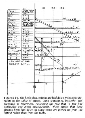
Starting with the original drawing by Robert Moore i came up with a general shape of the Tecumseths hull then taking that i refined it and finally refined the refined drawings to come up with a hull shape. To jump into the deep end and cover how the hull was drawn i am skipping over that and going right into the construction.
but when i look at plans there just isn't enough information on the plans to get an accurate shaped hull. Some plans have 3 maybe 4 waterlines spaced far apart which leaves a lot of empty space to fill in. Then another thing is there are no drawings of these ships built on the great lakes cira 1812 and what drawings there are, are "as built" so the ship was built first and plans drawn from measurements taked off the ship. When you look into master shipwrights they all were trained surveyors this suggests what they were doing is building hulls by the numbers using tables of offsets and or half hull models and not from drawings. Shaping the frames and building a hull seems to be esoteric intended for or likely to be understood by only a small number of people with a specialized knowledge.

Starting with the original drawing by Robert Moore i came up with a general shape of the Tecumseths hull then taking that i refined it and finally refined the refined drawings to come up with a hull shape. To jump into the deep end and cover how the hull was drawn i am skipping over that and going right into the construction.

- Joined
- Dec 1, 2016
- Messages
- 6,383
- Points
- 728

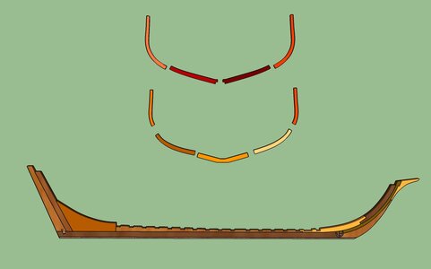
Doing a little investigative research i found 7 different ways frames were constructed and erected on the keel. Well! so much for the term "standard ship building practices" it might be closer to the truth to say each ship was a one off one of a kind. Common on all plans there is nothing at all to give the information as to the size of the frame timbers, how far apart they are spaced or how the frames were constructed. Lucky there is some remains of the Tecumseth that will give that information, making an accurate reconstruction possible.
Each frame was made up of 9 pieces in 2 overlapping layers which was typical of ship built on the Great Lakes
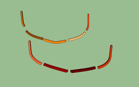
first layer is made up of a floor, first futtocks and a top timber. The first futtocks are moved into place with the ends butting the end of the floor.
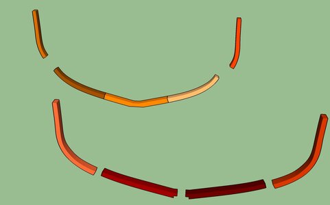
next came the top timbers and like the first futtocks they butt against the end of the first futtock
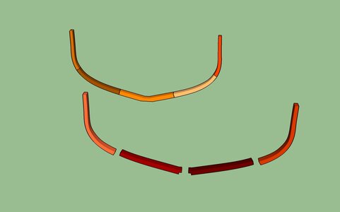
Next layer the second futtock was placed against the first layer. The futtock was notched to go over the keel and butt at the centerline.
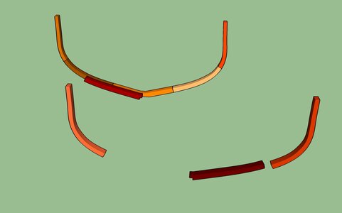
this timber overlaps the joint between the floor timber and the first futtock.
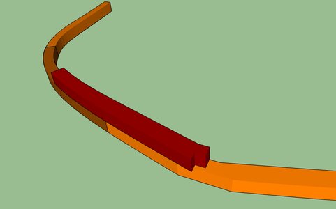
and the next piece is put in place and butts over the keel at the center
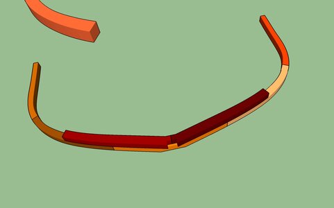
one of the top timber is now in place
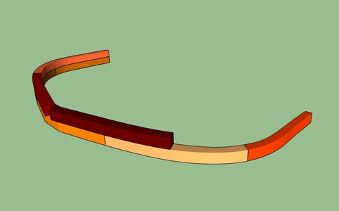
and the frame is complete
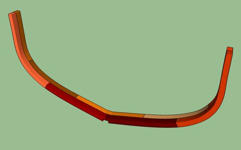
what makes this frame unique to the Tecumseth is when viewed from one side you see a notch that goes over the keel
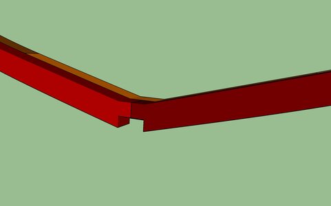
turn the frame around and there is no notch, the floor timber sits flat on the top of the keel.
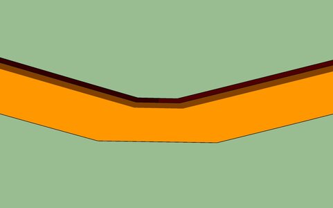
Each frame was made up of 9 pieces in 2 overlapping layers which was typical of ship built on the Great Lakes

first layer is made up of a floor, first futtocks and a top timber. The first futtocks are moved into place with the ends butting the end of the floor.

next came the top timbers and like the first futtocks they butt against the end of the first futtock

Next layer the second futtock was placed against the first layer. The futtock was notched to go over the keel and butt at the centerline.

this timber overlaps the joint between the floor timber and the first futtock.

and the next piece is put in place and butts over the keel at the center

one of the top timber is now in place

and the frame is complete

what makes this frame unique to the Tecumseth is when viewed from one side you see a notch that goes over the keel

turn the frame around and there is no notch, the floor timber sits flat on the top of the keel.

- Joined
- Dec 1, 2016
- Messages
- 6,383
- Points
- 728

This is how the frame fits on the keel.
the bottom of the floor is flat and has no notch it sits in the notch of the rising wood.
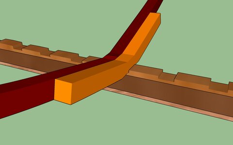
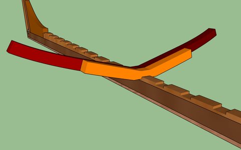
turn it around and you can see the first futtocks have a notch that sits over the top of the keel and they butt at the centerline.
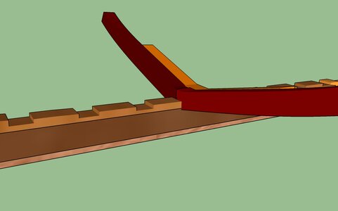
When i remove the first futtock you can see the joinery of the frame to the rising wood. We have notches going in two directions forward and aft along the keel and side to side. This seems to be a good way of locking the frame in it's location. Another common method was to notch both the floor timber and the first futtocks over the keel but in this method there were no notches in the keel.
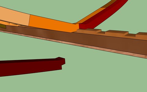
the bottom of the floor is flat and has no notch it sits in the notch of the rising wood.


turn it around and you can see the first futtocks have a notch that sits over the top of the keel and they butt at the centerline.

When i remove the first futtock you can see the joinery of the frame to the rising wood. We have notches going in two directions forward and aft along the keel and side to side. This seems to be a good way of locking the frame in it's location. Another common method was to notch both the floor timber and the first futtocks over the keel but in this method there were no notches in the keel.

- Joined
- Dec 1, 2016
- Messages
- 6,383
- Points
- 728

the 3D model shows us how the Tecumseth was framed so lets do it for real.
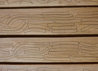
to start all the frame parts were layed out on sheets of wood and laser cut. Like i said in another post it took me 3 tries to get the drawings of the framing right.
Looking at the sheet there is a notch along the outer edge. Above the notch is not part of the frame it is a leg of the frame that will sit in a jig. This notch is at the sheer line of the hull and you will see later how that worked out.
There are any number of ways a model builder will approach the framing of a hull. This is my way and i am not saying it is the right or wrong way it is just how i do it. You as a builder can build anyway you want.
First i offset the the edges of the frames that notch shows how much bigger the frame is. If i were to cut exactly on the line for one thing i would be smaller than the final frame because of the kurf of the laser beam, then sanding off the char would make it even smaller. True the amount is extremely small but might as well give yourself a little extra. If i cut the frames to the exact size as drawn you would have zero tolerance to buid the hull, as you build each frame and install each frame you would have to be absolutely perfect because there is no room for error.

- Joined
- Dec 1, 2016
- Messages
- 6,383
- Points
- 728

What a wealth of information to read thru. She would be a great POF laser kit. Your 3D ability presents a clear understanding of how she would look. Thanks for this thread.
thank you mavRick
this thread is a presentation of the reserch, design, and building of the prototype as far as a kit being developed that is wide open.
- Joined
- Dec 1, 2016
- Messages
- 6,383
- Points
- 728

- Joined
- Dec 1, 2016
- Messages
- 6,383
- Points
- 728

Frames from 0 midship 1 to 10 aft and from A to F forward are all built the same way so i will do one to show what i did.
using the inside of the framing jig i first cut a pieces of scrap wood to fit snug into the slot running down the middle of the jig.
Next i can place the notches in the first futtocks into the end of the piece of wood in the slot. Then i lined up the outer edge of the top timber with the edge of the notch tab.
when i have the pieces lined up i super glue the ends, i learned the hard way to use something under the butt ends or you will end up gluing the frame to the jig. You can see pieces of plastic from packaging.
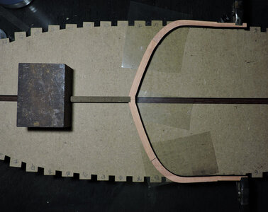
just to make sure i have the first futtocks at the correct angle i put the floor timber on top .
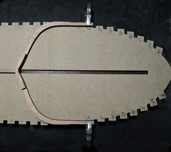
gluing the ends together do not have to be a strong joint. The over lapping timbers will give the strainght to the frame. I removed the glued up frame from the jig and used a wood glue to glue the floor in place.
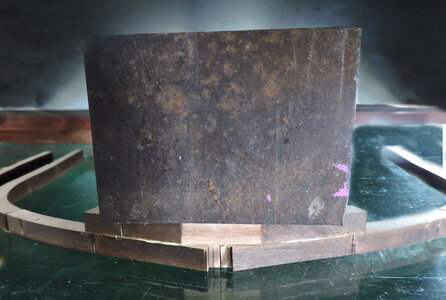
to line up the floor i used the top edge where the keelson sits.
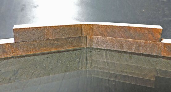
finally the rest of the frame pieces are set and a weight to hold them in place while the glue sets. I could clamp the frame parts together but building on glass using weight is a good way to be sure the frame is flat.
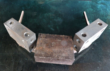
and the finished frame. The Tecumseth made a nice plank on frame project because you have only 17 frames to build plue the stern and cant frames.
Rather spending months building 60 or more frames in a larger hull.
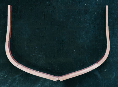
as a historical note
the frame floors and futtocks were attached to one another using both iron spikes and treenails. You will not see any spikes or treenails in the prototype model because it is just that a prototype and it used as a proof of concept. A model built for the museum will be built with better care and detail.
using the inside of the framing jig i first cut a pieces of scrap wood to fit snug into the slot running down the middle of the jig.
Next i can place the notches in the first futtocks into the end of the piece of wood in the slot. Then i lined up the outer edge of the top timber with the edge of the notch tab.
when i have the pieces lined up i super glue the ends, i learned the hard way to use something under the butt ends or you will end up gluing the frame to the jig. You can see pieces of plastic from packaging.

just to make sure i have the first futtocks at the correct angle i put the floor timber on top .

gluing the ends together do not have to be a strong joint. The over lapping timbers will give the strainght to the frame. I removed the glued up frame from the jig and used a wood glue to glue the floor in place.

to line up the floor i used the top edge where the keelson sits.

finally the rest of the frame pieces are set and a weight to hold them in place while the glue sets. I could clamp the frame parts together but building on glass using weight is a good way to be sure the frame is flat.

and the finished frame. The Tecumseth made a nice plank on frame project because you have only 17 frames to build plue the stern and cant frames.
Rather spending months building 60 or more frames in a larger hull.

as a historical note
the frame floors and futtocks were attached to one another using both iron spikes and treenails. You will not see any spikes or treenails in the prototype model because it is just that a prototype and it used as a proof of concept. A model built for the museum will be built with better care and detail.
Last edited:
- Joined
- Dec 1, 2016
- Messages
- 6,383
- Points
- 728

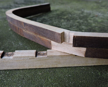
The bottom of the frames will look like this on the first futtock side
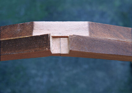
and like this on the side of the floor
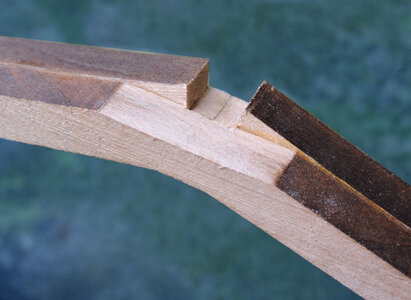
i did testing to see if parts will glue together if you do not clean off the char and sometimes they do and sometimes not. So it is inconclusive to be safe about it i do scrape most of the char off before gluing.
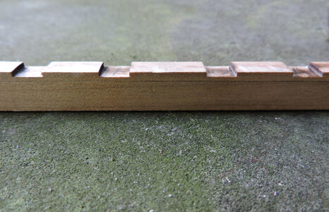
all frames 0 midship 1 to 10 and A to F are ready to be placed on the keel
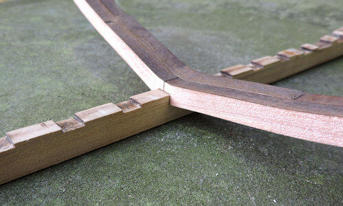

and like this on the side of the floor

i did testing to see if parts will glue together if you do not clean off the char and sometimes they do and sometimes not. So it is inconclusive to be safe about it i do scrape most of the char off before gluing.

all frames 0 midship 1 to 10 and A to F are ready to be placed on the keel


- Joined
- Dec 1, 2016
- Messages
- 6,383
- Points
- 728

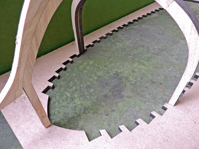
i have built hull without a jig with good results and i have built hull with a jig. You do not need a jig but it make building the hull easier, for the Tecumseth i laser cut a jig. As you can see by the ruler the jig is 30 inches so this is a fair size hull.
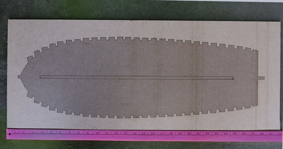
what i did was duck tape a pieces of plastic to the back because first i am not going to glue the frames to the jig and with a backing i can move the hull around for photography.
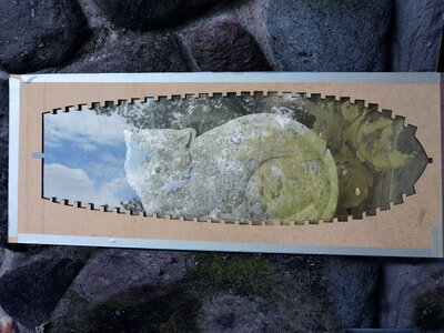

what i did was duck tape a pieces of plastic to the back because first i am not going to glue the frames to the jig and with a backing i can move the hull around for photography.

- Joined
- Dec 1, 2016
- Messages
- 6,383
- Points
- 728

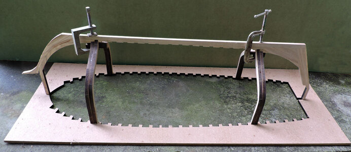
back building the frames i used the inside of the jig to set the frames by lining up the top of each leg with the outer edge of the notch tab, here you can see why, the legs fit nice and snug in the slots. Should a little error creep in and the legs do not quite fit the notch there is enough movement in the frames you can glue the frame legs to the jig in order to hold them in place.
setup is the first and last full frames F and 10
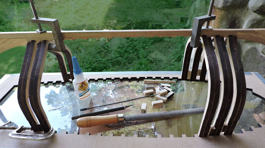
then i built inward to the midship using blocks between the frame legs guled in place with super glue.

setup is the first and last full frames F and 10

then i built inward to the midship using blocks between the frame legs guled in place with super glue.

Last edited:
- Joined
- Dec 1, 2016
- Messages
- 6,383
- Points
- 728

I realize most builders on the forum do not design and build from scratch so details on drawing a jig is not necessary. This is more of a why it was done this way. Many folks in the hobby attribute the building in a jig to Harold Hahn but actually it started with Robert Bruckshaw, Hahn refined the idea for the hobby. When first introduced to the hobby builders thought the method was a huge waste of wood to extend the frames above the hull. Yes it uses more wood but "huge" was a huge exaggeration. In this case it used 1/2 a sheet more material by adding the legs to the frames. Builders thought by placing the hull down into a jig would save on materials or they just did not want to copy Hahn's idea who really knows.
The concept of using a jig was first to locate the frames and keep them perpendicular and square to the keel and also level from side to side then to hold and stabilize the framing so the hull could be sanded to it's final shape. In my logic you can not sand the hull if it is sitting in a jig and removing it defeats the purpose.
some kit manufactures are coming up with more and more complex and elaborate jigging ideas, what really applies is the KISS method Keep It Simple Stupid.
What i decided to do was use a jig to build the hull and gluing blocks between the legs to strengthen the hull so i could sand it.
Last edited:

