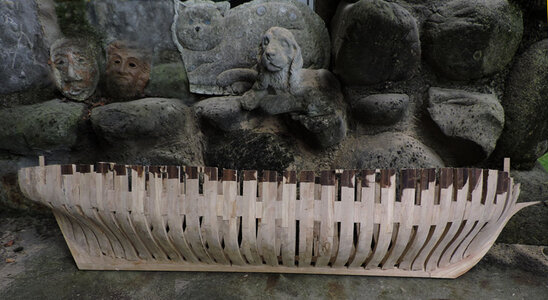
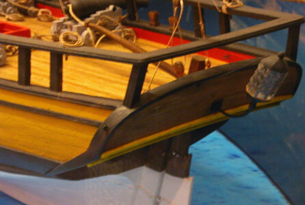
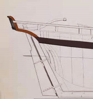
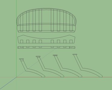
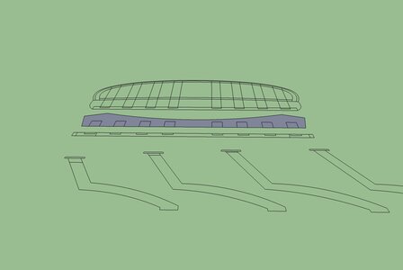
Tecumseth 1815

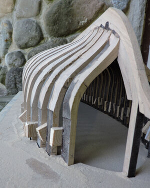
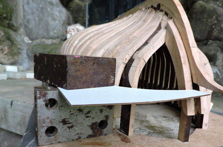
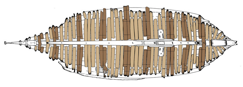
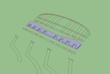
in the last image in the post above i held the mockup together with T pins so i could take it apart. and scan the shapes. You can see the edge of the bevel a bit fuzzy but enough to be able to accuratly draw them.

img042.jpg
 
building the bow

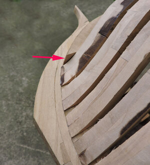
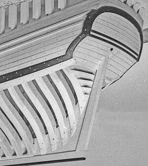
You can see some char left on frame "K" unlike the the problem at the stern there is enough material on the bow frames to allow further sanding. I did not finish the sanding on frame K because i will shape frame K along with the bow timbers

bow1.jpg

the pieces to install are the knight heads

bow2.jpg

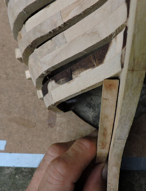
the foot of this piece fits against the stem and at the foot of frame K at an angle

bow3.jpg

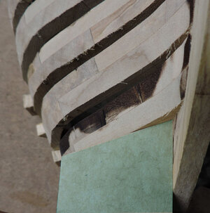
i used a piece of cardboard to make a template of the angles.

bow4.jpg

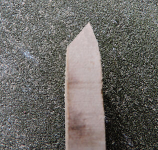
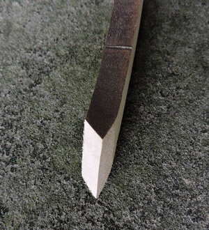
then saned the end of the knighthead to the angles

bow5.jpg

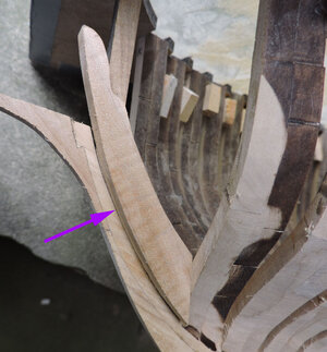
the edge of the knighthead runs along the inside edge of the apron and against frame K

bow6.jpg

at this point there is no bevel cut into the knighthead and you can see where it extends above the edge of frame K

bow7.jpg
 
from the drawings i made a template of the bow

bow8.jpgbow9.jpg
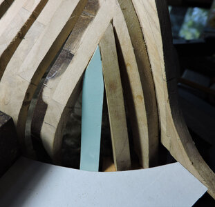
i did this as a guide for setting in the rest of the bow timbers, each timber fits at and abgle to frame K and the timber next to it so i made templates of the angles

bow12.jpg

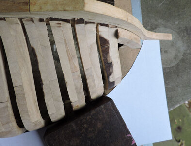
each timber was cut to its angle.

bow13.jpg

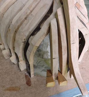
then fit to the bow using spacers.

bow10.jpg

once again you can see the foot of the timbers sticking above frame K.

bow11.jpg

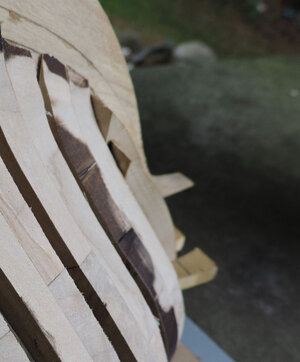
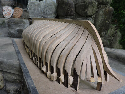
once all the bow timbers are in place sanding can begin.

bow15.jpg
 
Next i will move on the setting the wing transom and stern timbers then the deck clamps and building the deck structure. But before i continue there is a question on the framing of the Tecumseth.
This is one of those issues of conflicting information and very difficult to resolve. There seems to be a wide gap between academic circles and the general public and the hobby of model ship building. In academic circles information is freely exchanged and made available, as for the public the information is there IF you make the trip to the library, historical society or museum.
Here is a drawing of the framing of the Tecumseth done by John Stevens museum curator

Note it looks nothing like the framing of the model. John Stevens studied the wreck so you would think his drawing would be accurate. The framing is to old English system of double frames with filler timbers between the frames.
Question is did John Stevens just assume this is how the hull was built or did he base this on actual wreck data?
There are 57 images of the wreck in the archives of the Museum, problem is they have not been scanned so there is no digital copies, you have to go to the museum to view the images. John Stevens also did a field report which is also in the archives.

js plan1a.jpg

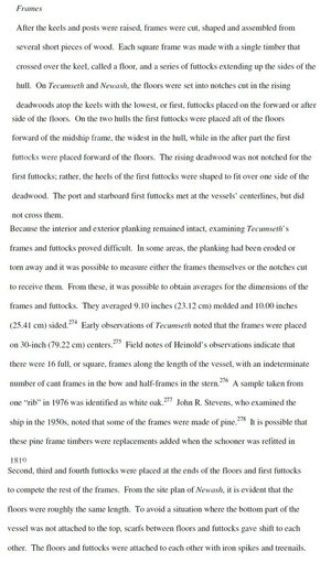
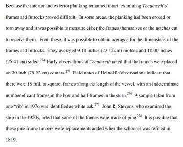
a thesis done at Texas A&M note the statement "because the interior and exterior remained intact examining Tecumseth's frames and futtocks proved difficult. Well, if that is the case what did John Stevens base his frame drawing on?

frame.jpg

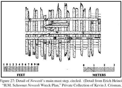
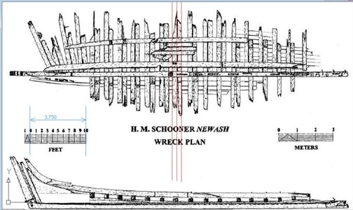
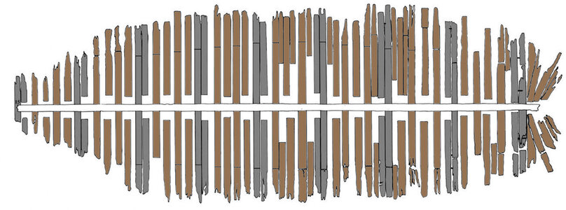
This seems to be a conflict of information what we see here is a drawing of the Newash the sister ship of the Tecumseth built side by side by the same crew. Note ALL the frames are sister or double frames and not like John Stevens drew.
Question why would a crew build two ships side by side and use a totally different system of faming on the two ships?

frames newash.JPG


to resolve this first the field notes of both John Stevens and Eric Heinold would have to be studied, the 57 images of the wreck could be looked at to see the nail pattern in the planking to see if the frames are together or set apart. But this is not available nor will the museum staff take the time or effort to research the question.
 
What i see interesting in John Stevens framing is first WHY? shift the frame timbers there are no gun ports in the way so i see no reason to shift the timbers. Also note by shifting the timbers the frames are not attached to one another like the double frames because they are not bolted together, nor can they be joined at the foot and head of the timbers because of the shift. Conclusion is the frame between the sistered frames are not frames just loose timbers.

At this point can i call the Tecumseth a historically accurate model of how it looked and was built? NO! not without a lot more research, time and money
maybe the Tecumseth was rebuilt at some point and frames were ripped out and replaced by floating filler timbers.

you would have to really take this hobby serious to take a trip to the museum in N.S. Canada to study what they have in the archives then a thousand miles away make a trip to discovery Harbor to take a close look at the timbers. Then somehow convince Texas A&M to send copies of everything they have on the Tecumseth. Or just say "good enough" for a hobby model.
 
Last edited:
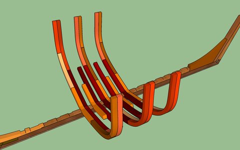
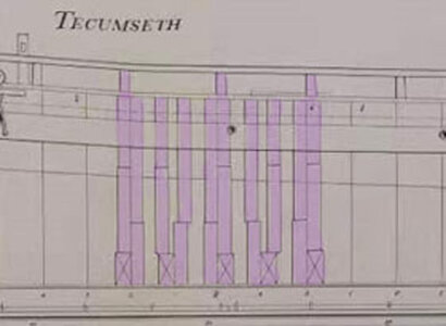
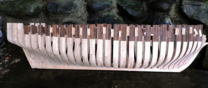
Building a computer model allows me to change whatever i want and see how it works so looking at how the Newash was framed and how i framed the Tecumsth looks like this. building a hull with sistered frames all the frames would be built and stood up on the keel.
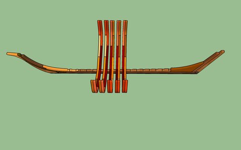
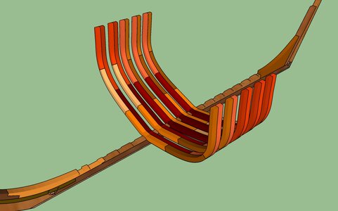
framing1.jpgframing3.jpg

if you were to build a hull as suggested by the John Stevens drawings you would built the hull this way. You would build every other frame and set them on the keel, then set in the floors and first futtocks between the doubled frames.

framing4.jpgframing5.jpgframing6.jpg

next you would have to plank the hull to the top of the first futtocks then add the second futtock by jamming it between the interior and exterior planking. Plank to the second futtock and add the top timbers.

Looking at this method of framing the frame parts could not attach to the heads of the futtocks below because they are offset nor attach to the futtock along side. So the frame parts float and there is nothing holding them in place other than the planking.

This is a very old style of building of planking first and wedging in filler timbers. At some point the British builders seperated the filler frames into 2 single frames with the parts attached to one another with overlapping scarf joints.
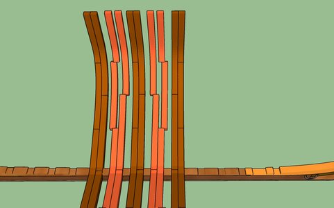
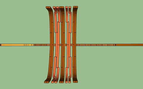
framing7.jpgframing8.jpgframing9.jpg

John Stevens drew his plans of the Tecumseth in the early 1950 and at that time there were no wrecks that were studied and research information was hard to come by. There was planking inside and outside the hull so the actual framing was not visible, John Stevens took an educated guess and used what might of been known at the time about British hull framing.

The Tecumseth was not exactly studied as an archaeological site the hull was ripped apart by a dredge and there was just a heap of pieces to look at.
We can now look at ship wrecks and parts of the time period and piece together construction information.
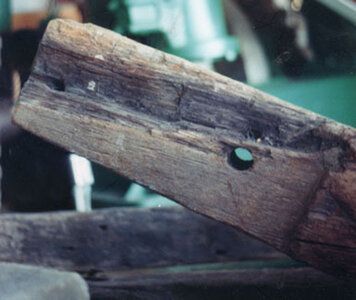
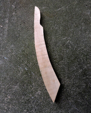
in the following images we can clearly see the futtocks were joined by overlapping scarfs. In the last image we see a hole for a wooden treenail as well as a hole at the end made by a spike. Study of the Tecumseth did state both treenails and spikes were used to build the frames.
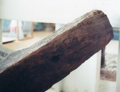
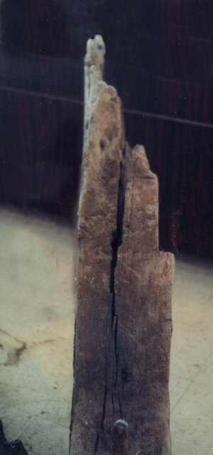
floor 5.jpgfloor 8.jpgL floor 6.jpg

Were chocks used in the construction of ships on the Great Lakes? probably not, generally speaking, because there is always an exception to the norm.
a builders contract of the time period does state scarfs were used,
Back in yards in England timber was getting harder to get, an overlapping scarf of 3 1/2 feet would use much more timber than a chock, but around the Great Lakes one thing there was plenty of and that was standing timber.
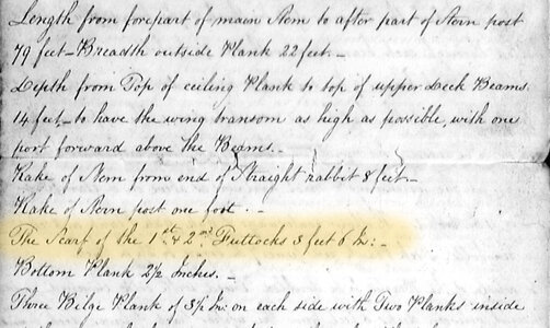
specs.jpg
 
Last edited:
thanks jmsky

just about everything from this point forward is guess work because nothing survived of the deck and stern. I will have to rely on other wrecks of the time and place to fill in the blanks. Around 1800 there weren't any shipyards around the Great Lakes so there were not many master shipwrights either. Other than Kingston, Amherstburg and Quebec that were the ship building centers. I would think the Great Lakes including Lake Champlain did not get much influence from the east coast on ship building which kind of made the inland seas a closed system. What one shipwright did could very well been copied by another. Shipbuilding like any other craft or trade was like a guild of craftsmen who must of exchanged ideas.
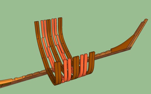
Take the use of deck knees they were not used in Great Lakes building existing evidence suggests Henry Eckford, Noah Brown or Willinam Bell did not use deck knees when they built lake vessels. The boom in ship building post 1812 war show from wrecks knees were not used in the construction of the lake schooners.
 
At this point of the build i want to install the wales, i left a notch in the frames when i offset the width inside and outside. Now that notch comes into use because it left a clear and sharp line for the top of the hull which i used to measure down to the bottom of the wales. I could install the wales at this point but the clamps i have did not reach deep enough into the hull with the extensions above the frames.

w1.jpg

Before i cut down the extensions i added blocks between the frames at the height of the wales, then i cut down the extensions. On the first side of the hull i cut down the extensions first and realized the hull becomes very weak and the frames can be broken or the hull becomes distorted. This is why it is a good idea to either build a hull using spacer blocks between frames or build the hull in a jig.


w2.jpg

The spacer blocks gave me a strong longitudinal belt running lengthwise down the hull. If you built a hull that sat down in a jig i do not see how you can install the wales without removing the hull from the jig. Removing the hull defeats the purpose of the jig holding the frames in place. The filler blocks will be covered by the wales on the outside of the hull and by the deck clamps on the inside.
I did notice the pros and cons with using Super Glue, it is really strong and you can not pull apart a glued joint and it is good for instant holding parts in place. The problem i found out you can easly snap apart a joint. If you wedge a knife or small chisel between a joint a quick pull will snap the joint apart or if you hold the top of a frame and give it a quick pull you can easy snap the foot of the frame from the deadwood.
So the wales will be glues to the face of the frames and blocks using Titebond wood glue

w3.jpg

In order to bend the wales to the hull i first soaked the wales in hot water for about 30 minutes, this made the wood soft and easy to bend around the bow. I let the wales clamped to the hull over night until they were dry and then removed them. Once dry they held the bend.

Bending wood depends a lot on the wood you use, some woods just do not like to be bent. There are woods that are naturally brittle or so hard and dense bending them becomes a problem and require more that just a soak in hot water, these have to be steam bent or soaked in water and bent using something hot enough to turn the water to steam. In kits the wood used has been kiln dried way down to maybe 6% to 8% moisture then sit around and dry out. There is no amount of soaking that will restore the flexibly of the wood. Using naturally seasoned wood is the best. I have used Poplar, Red Maple, Beech, Cherry, American Walnut, for bending and they all work well. I also use India ink to blacked wales.

w4.jpg
 
Hello, Dave.

I am in no way an expert in framing and don't take my comments as criticism. At the photos above, it looks to me, that frames are wide\thick for such a vessel. Again, it is just my personal observation, and if you can clear my doubt that would be great. I am comparing frames with an Alert cuter I am building now.

Thanks in advance...


thank you Jimsky for your keen observation yes the frame do look to wide so i went back and checked the data

frame size.JPG

from the archaeological report it stated the frames were 10 inch sided the measurement from bow to stern.
what made my heart skip a beat is the word "THEY" did that refer to the full double frame or each futtock that made up a frame? it makes a huge difference so either the frames were 10 inches or 20 inches depends on what "THEY" are futtocks or frame.

so i went back to the archaeological and historical research
there were several studies done by C.H. Snider, Rowley Murphy, H.F. Pullen and John Stevens The reference i will refer to was done by a team from Texas A&M university led by the graduate student Erich Heinold this was a comprehensive study of the twin schooners Tecumseth and Newash.
Keep in mind these two ships were built side by side by the same carpenters and master shipwright.


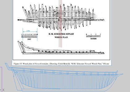
i took Erich drawing of the framing and imported it into CAD then scaled it to the model size 3 3/4 inch = 10 feet and drew the red lines to the width of a frame.

frame size1.JPG

below in blue is the cad drawing of the hull and framing

frame size2.JPG

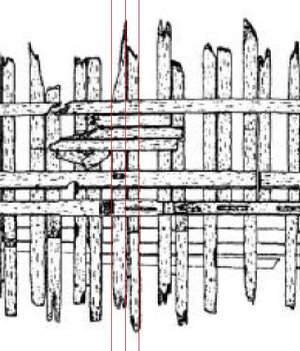
taking a close look of the original drawing and the red cad lines over the drawing

frame size3.JPG

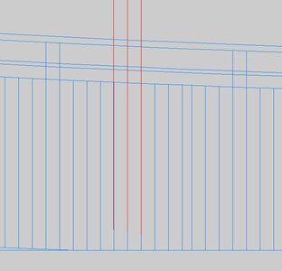
when i overlay the red traced lines over the CAD drawing the width of the frames are within a fraction of an inch.

frame size4.JPG

conclusion the size of the frames are correct
checking other sources it seems the framing is consistant with ship of the same size and tonage.
 
I am comparing frames with an Alert cuter I am building now.

you really can not compare the Alert to the Tecumseth and Newash or for that matter ships built in north America. Early in the colonial period some ship were built with bends and filler timber but that system gave way to the double sistered system which became the standard.
The Alert was most likely built with double bends and between the bends loose filler timbers were used.
this framing looked like this.
Frame futtocks in this system had an average size of 6 to 7 inches compared to the Tecumseth which had frame futtocks of 10 inches.

as you can see and from the 3D frame model in post #89 the planking held these timbers in place, they were not attached to one another nor the foot to the head of each futtock. Remove the planking and all the filler timbers fell out.

nancy.jpgreader point.jpg
 
Last edited:
soaking and clamping the wales on the hull until they dried
i am using Poplar because it bends nice and takes an even stain with India Ink.


B1.jpg

B4.jpg

at the bow make sure you start the bend as close to the end of the wale

B2.jpgB3.jpg
 
Last edited:
Here is the thing with model ship building

There is a certain order to the build and things have to be done before something else. We know the wales start at the stem and we know how far down from the top of the hull, but what about where they end at the stern?

2hannah54.jpgd14.jpgd15.jpg

The wales seem to end at the level of the wing transom

d16.jpg
There also seems to be different ways the stern molding and the way the molding and wales join

d13.jpg

this is how John Stevens drew the stern molding and wales which it pretty typlical so that is what i am going with.

js plan1.jpg
 
ok fine we have to know the exact location of the end of the wing transom and how the stern is going to be built

While i am soaking and bending the wales it is back to the drawing board

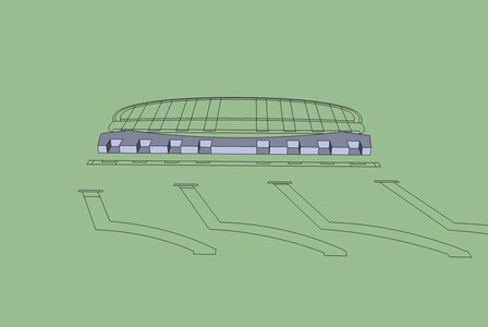
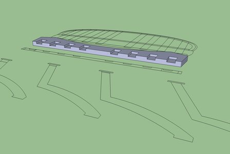
first i take the CAD drawing of the stern structure

Capture.JPG


and select the wing transom

d2.jpg

give it a dimension on the Z

d3.jpg

d4.jpg

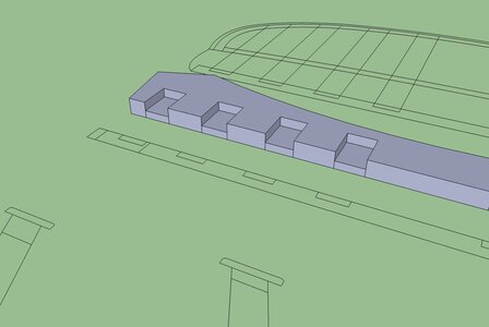
next is setting the depth of the notches for the stern timbers

d5.jpg


and i have a vertical reality wing transon

d6.jpg
 
Back
Top