The Naval Cutter ALERT- 1777, POF by Jimsky

Jimsky, I don't know but looking at the beam in Jolley Roger's picture it looks to me like there are wide notches (for bitt) both on the stern side and the bow side. Maybe for the carrick bitt at the stern side and for the pawl bitt at the bow side. I assume Jolley Roger made 2 of those notches himself?
Looking at the drawings page 40-42 in the manual it seems to me Trident has designed the pawn bitt and the carrick bitt close together.
 
Greeting all! Hope you are all healthy and enjoying the weekend with your families, friends, doing some work in your shipyards. :)

While I was learning the next few steps for the assembly, and browsing the instruction manual I came across some discrepancies and would ask you folks for a hand. The question for those who already completed the Lover Deck beams installation. The instruction manual, page 27, fig. 6.11 depict the Lover Deck beam plan (see below). look at the first beam towards the bow, part #DL3. There are two notches for the Pawl bitt pins. Those bits are parts of the bowsprit assembly - kit parts are FL6/7 and FL8/9. Make a note: The notches are looking towards the stern!

View attachment 197207

Furthermore, this proved by checking the AOTS book drawings. Red circled showing the beam (DL3), and part 24 at the drawings, is the Pawl Bitt pin (the left one if facing the bow)

View attachment 197215

Everything looks good so far, correct? But if you check the lover Deck Plan (most recent documentation) provided as help for cabin installation, you will find that part DL3 notches facing the bow (opposite) direction. This further seen in the Wang build log (image below)

View attachment 197216

Wang's model (taking from his build log)
View attachment 197217

...so, here is the question. What should be considered as the correct posion for the build? Many thanks who will chime in! Enjoy the weekend.

Jimsky​

This is correct, gap should be toward the bow

1607311091841.png

Suite should be developed according to this picture, suites have all these parts in this place I just replacing the parts with red wood did not increase new parts

1607312147893.png1607312592968.png1607312717588.png1607312847875.png1607312846662.png1607312985687.png1607313097914.png
Hope these can help to you
 

Attachments

  • 1607312760550.png
    1607312760550.png
    2.6 MB · Views: 12
Seems Trident opted for the alternative bitt instalation.
Thanks my friend, It is very hard to say what was the correct position. The AOTS book has discrepancies' all over the place. On one page they show one direction (Stern), on another page (close view) it shows the bow direction. Personally and from an engineering perspective facing Stern should be correct. If you wind the windlass the force on the 'pawl bits' goes the opposite direction and the beam (if facing the stern) holding this force alone with the upper beam. But we will build according to the kit design avoiding unfit other parts while continuing assembly.
 
Ji Jim, the bow direction version is mentioned in the aots book as an alternative and this is what trident picked.
From an engineering perspective I fully agree with you, it should be placed at stern direction for the main deck beams and bow direction at the lower deck beams then you best carry the torque load of the anchor cable at the bitt.

Other prominent items are also the round and the square gun ports, they are both shown in the book.

The shipyard kit shows the square, where Trident picks the round gunports.
mk019-hms-alert-no-50.jpg
1607313097914.png
 
Other prominent items are also the round and the square gun ports, they are both shown in the book.

The shipyard kit shows the square, where Trident picks the round gunports.
Good point, Maarten. Most of the plans and at least the 'Half-breadth' plan is based on the Rattlesnake (1777) a sister's vessel to the Alert. There are modifications to Alert. These improvements included the addition of a fifth deadeye and a longer channel. Other modifications entailed moving the third gunport further forward and making all gunport square.
 
Trust me the whole build from this point is a series of modifications( just don't stray with the core hull to much). There are lots of future dependancies based on past decisions. ( I'm just finding that out the good way! luckily)
Absolutely agree with you, John. The kit is just a base and collection of materials. It just gives you a basic idea of what and when to do. But it is us who make out of this kit a model. I am making some adjustments based on the situation. 1mm can make a huge difference, either way, though.
I cannot imagine what would happen if all our Alerts would look identical (I mean absolutely the same)...ouch :eek:
 
Sorry Jim bit of future talk here.

Hi Daniel I think your choice to cut back all the ribs and do a DYI rails was a blessing in disguise. The fitting ( and serious adjustment) of the rails as they are supposed to be is interesting process! BTW anyone find the bit in the manual for the main mast deck supports!
 
Time for the update, folks as we are continuing with the frames assembly and installation. As always, thank you very much for your interest and invaluable support. :)
We are continuing with the rest of the frames. Technically, they should be assembled and processed the same way as the cant frames. Assembly MDF jigs were provided by Trident for all the frames in the kit, they are laser cut and engraved with the corresponding numbers. Below is a typical framing jig provided in the kit. Note a 'locking' part. They are by mean to lock the frame in position while glue sets.

600_0878.jpg

If you will try to insert floor timbers or first futtocks into the jig, it will not fit. The recess to set floor timber or first futtock has to widen according to your receiving recess of cross chock or floor timber in the rising wood. So...:" what is the 'heck', Jim, you are re talking about??? "
Well..., remember our frame disposition beautifully drawn in isometric by Peter Goodwin (page 61 in his Alert book )

1608137748294.png
Highlighted yellow, are the parts I am talking about. specifically part number 17 on the above drawing. The floor timber and first futtock recesses need to be shaped as per recesses in your rising wood. I think, if you take a look at the below image (red arrow), you will have this 'Aha' moment.

600_0876_edit.jpg

So what size it should be shaped\enlarged? The answer is simple enough, it should be the size of the notches of your kit's rising wood parts BL9, BL10, and BL11. Before widening the recess check the size of the corresponding recesses on the rising wood. As you can see in the above image, the floor timber from frame 17 won't fit in the jig. The size between the arrows needs adjustment. A good starting point to widen the recesses - is the jig. Why? Because while you make the notch wider, the jig will keep part symmetrical as the floor timber must fit into the jig without gaps (brilliant design, IMHO). It may require many times 'shape & try' until jig, and mostly you are happy. Ruffly the recess size should be 4.8mm ~ 5.0mm. Warning: the actual size is only determined by the size of the actual recesses (notches) on your own kit's rising wood.
Here is the image from the Trident Model, this was not included in the instruction manual. But Trident model responded to Paul's @paulv1958 build log. The shaded area is the amount of timber, you will have to remove. 0.5mm is not the absolute value, please measure your own deadwood recesses so the frame will snag (not loose). You have been warned :cool:

1608429364921.png


600_0877.jpg

The rest should be relatively easy, and repetition of the assembly of the cant frames. All frame parts must fit the frame without the gaps.
600_0882.jpg

another side view
600_0883.jpg

600_0884.jpg

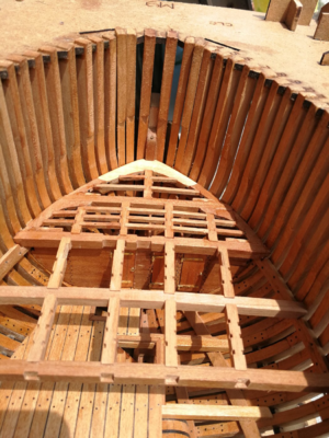
As a result of my hard-working evenings, I was rewarded with this...

600_0890.jpg

I was happy until... while inserting frame 55 realized that it didn't fit nicely. it didn't 'play' with the rest of the adjacent frames. Ouch...I was glad it broke while I positioning it. The first futtocks were labeled incorrectly...Dah!!!

600_0898.jpg
Again, I regret the kit doesn't supply a formal draft for all the framing parts so I can make a new one. But... Wait...the laser cut inserts, the one from frame 55!!! Yea..baby...so I made the new out of SwissPear.

600_0899.jpg

The new floor timber does have a distinct color, but I can care less as it will be hidden mostly anyway. Here are the laser cut insert (top), an old, wrongly labeled floor timer (middle), and the newly scratch built (bottom).

600_0900.jpg

Each frame carefully shaped using the glass as the base. On the glass, I put a 230grit sandpaper sheet, it makes sure the frames don't move while you sand the frame. long enough sanding stick ensured both ends of the frame covered while sanding.

600_0891.jpg

The last process in the batch frame production is to 'bolt' the frame's components. It is absolutely optional and doesn't require at all, hence, most of them will be covered anyway. However, I decided to present 'bolt' and those came up to my acceptance level!

600_1085.JPG

600_1087.JPG

600_1086.JPG

600_1089.JPG

Many thanks, to be continued
 
Well done,

The floor notch miss size is an error in the rib bases, as it is consistent every 2nd rib. It just has to be delicately filed out.( the keel is consistently sized, I used its thickness as a guide, not the templates),

Warning. if you do decide to glue/ fasten the doubles together, leave the top area 2-3 inches that gets cut off unglued/loose as the varying size ribs that go through the upper cover plates are mostly those doubles and it makes it hard to cut them out to the right length.( hope that makes sense)

Paul ( AKA John :cool:)
Thanks, Paul. This is exactly what I've warned. Measure recesses on your own rising wood for a perfect fit. But thus far, the templates work in my case as the starting point, then if needed I shape them in-place.

For double-frames, It does make perfect sense, but in my case, it is too late. Oh...well... But for the rest of us, it is a really good hint. Many thanks!
Ohoh for me too late also. @paulv1958 good tip.
I think we have now a lot of additional cleaning, filing, sanding and swearing to do. :)
 
Back
Top