I am glad that the small gun captain inspecting the work moved out of the way so that his feet and legs were not runover with the recoil celebratory salute! Nicely done. RIch (PT-2)NIce up-ticking on your part. Rich (PT-2)
-

Win a Free Custom Engraved Brass Coin!!!
As a way to introduce our brass coins to the community, we will raffle off a free coin during the month of August. Follow link ABOVE for instructions for entering.
-

PRE-ORDER SHIPS IN SCALE TODAY!
The beloved Ships in Scale Magazine is back and charting a new course for 2026!
Discover new skills, new techniques, and new inspirations in every issue.
NOTE THAT OUR FIRST ISSUE WILL BE JAN/FEB 2026
- Home
- Forums
- Ships of Scale Group Builds and Projects
- HMS Alert 1777 1:48 PoF Group Build
- HMS Alert 1777 1:48 Group Build Logs
You are using an out of date browser. It may not display this or other websites correctly.
You should upgrade or use an alternative browser.
You should upgrade or use an alternative browser.
Very nice work Jim,
My hands start itching looking at your puctures, but I still have a lot to do before being at that stage.
My hands start itching looking at your puctures, but I still have a lot to do before being at that stage.
Thank you, Mon Amie!My hands start itching looking at your puctures, but I still have a lot to do before being at that stage.
Ha..ha... I just needed to take a break from the main assembly, still have to catch you in planking both inside and outside, a long way to go...but a really pleasant one for sure!
Many thanks, Stephan! If anyone curious why SOS is really popular among others forum - because we share the knowledge (no secrets). Today you learn from my build log, tomorrow I will learn from yours! Isn't it great!!Read all, good advice in the build, and learned a lot on how to do things. Great build and will follow this with great interest
Hallo Jim,No worries, Rich!
1) The AOTS stands for Anatomy Of The Ship. This is series of books about a particular ship. It is a kinda monograph, similar to ANCE publication, however doesnt comes with separate printed plans. All plans inside the book. Check this out.
Anatomy of the Ship series - Wikipedia
en.wikipedia.org
Peter Goodwin wrote the book 'The Naval Cutter Alert 1777' is part of this series. I use this book as the reference for my build
View attachment 218132
2) IMHO In My Humble Opinion
maybe it is a good place to show the members also the review of this very helpfull book, especially for the modelers building this kit model of the HMS Alert
Book review - The Naval Cutter ALERT 1777 (Anatomy of the Ship)" by Peter Goodwin
Book Review: The Naval Cutter ALERT 1777 (Anatomy of the Ship) by Peter Goodwin Hardcover: 120 pages Publisher: Conway Maritime; Revised edition (April 19, 2004) Language: English ISBN-10: 0851779689 ISBN-13: 978-0851779683 Product Dimensions: 10.2 x 1 x 10.2 inches Shipping Weight: 1.7...
shipsofscale.com
BTW Jim - Very good work on the gun carriages - very well done - and the kit is providing a very good basis to get such a result
Many thanks, Uwe! I think it is a brilliant idea. Since you make a book review, the cost and value of this book went rocket high. At some places it sells for more than $500.00Hallo Jim,
maybe it is a good place to show the members also the review of this very helpfull book, especially for the modelers building this kit model of the HMS Alert
They are not selling - they are offering for this amount - but every day a stupid modeler is bornMany thanks, Uwe! I think it is a brilliant idea. Since you make a book review, the cost and value of this book went rocket high. At some places it sells for more than $500.00
The Naval Cutter Alert 1777. | Bokbörsen
Här finns så gott som allt som givits ut på den svenska bokmarknaden under de senaste hundra åren.
600 SEK are appr. 59 Euro / 70 US$
Here are some searches in the book finder...
 www.bookfinder.com
BookFinder.com: Search results
Find nearly any book: new, used, rare and textbooks. Get the best deal by comparing prices from over 100,000 booksellers.
- Joined
- Aug 8, 2019
- Messages
- 5,573
- Points
- 738

https://www.amazon.com/Naval-Cutter-Alert-Anatomy-Ship/dp/0961502185
$157,00
€1.110,47

Pricewar
The first one is a new book, second hand in list is 100 dollar more
$157,00
NAVAL CUTTER ALERT 1777 ANATOMY SHI : Goodwin, Peter: Amazon.nl: Boeken
NAVAL CUTTER ALERT 1777 ANATOMY SHI : Goodwin, Peter: Amazon.nl: Boeken
www.amazon.nl
Pricewar
The first one is a new book, second hand in list is 100 dollar more
No kidding, Stephan. I bought this book (used) for $35.00 I guess if they buy it for 100.00 - it is in demand...Pricewar
The first one is a new book, second hand in list is 100 dollar more
- Joined
- Oct 26, 2020
- Messages
- 38
- Points
- 78

...I bought Goodwind´s "Alert 1777" two months ago (used but in very good condition) at a price of 40,-- engl. pounds, after several days of searching; the prices I found at other sellers varied from 100,-- EUR to the amount of 500,-- EUR and more...
Best regards
Fritz Baur
Best regards
Fritz Baur
google is your friend for all things pdf!.
Greetings from rainy Brooklyn, folks.  It is miserable and annoying but...at home, it is cozy and warm.
Today will be a short update from a previous post. Well..., I thought, I have finished with the cannons assembly overview, as declared quality 'out of the box' is dissent for the most part, but...something bothered me as incomplete and I thought about ways for improvement. So... here you go - Jim's way to improve the overall canon appearance.
I recall Triden Model told us that kit provided a solid base, and there are many ways for improvement. So I decided to improve the kit's cannons. One of the improvements made is in the canon trucks. Kit provided trucks as laser-cut, and the axletree hole was not round and perfectly centered. Obviously, you can make it round but this will require more sanding, and as the result, the trucks will be smaller than the required size. The second issue is the timber itself, it doesn't look good under oil, The material is very porous and soaks the oil like a sponge.
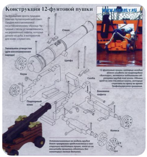
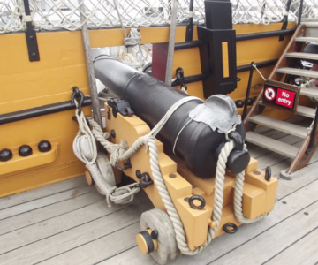
Original trucks were made from multiple timber pieces laminated and bolted together. Take a look at the images below.
The timber selection was easy, I cut the strips out of Pear and Castello just to see what would look better. Strips were glued together on the glass to make it perfectly flat and even.
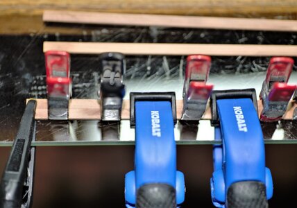
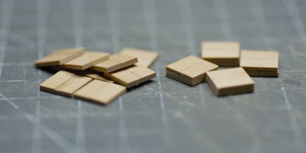
Note two types of clamps: the metal clamps holding two strips together while glue sets, the plastic ones (blue color) holding the stips flat. The strips are only 1.5mm thick. Once the glue dry, using the tablesaw cut the strip assembly into the squares.
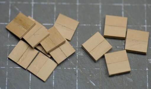
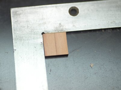
Now we will glue both squares together. Just make sure it is perfectly square (this is a 'must' for drilling the holes in the jig). Also watch out the line direction: both squares must form the 'plus + sign' e.g. on one side the line should be vertical, on another side it should be horizontal. I use machinist square to control the squareness
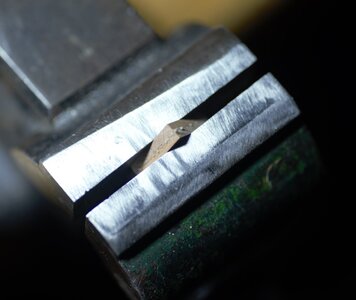
To make sure the glue evenly spread, I used the vise.
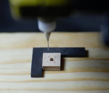
Time to drill the holes for bolt imitation. When repetition of similar work is involved, I always looking for jigs. A very simple jig was made to drill the holes, but this one ensures the holes were made on equal distance (assuming you have a perfect square). First, we will drill the axletree hole, because the diameter is the same for both hind fore axletrees.
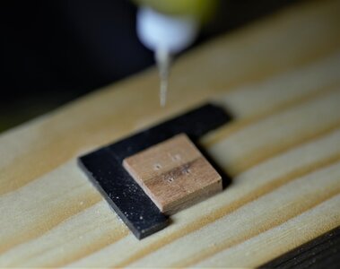
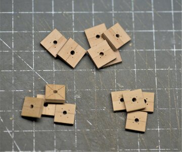
Take a look at the above photo. There are two types of blanks: some of them for fore tracks, they will be larger than a hind truck, therefore the bolting pattern different. The next step in sequence - to make bolts. This time, I use brass wire 4.00mm, just insert the wire and cut flush on both sides. Time to make the wheels round. I use the wood lathe and turning chisel.
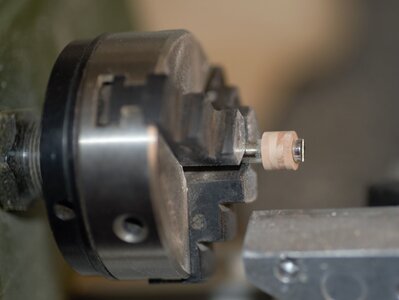
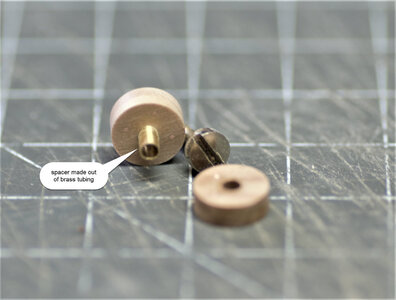
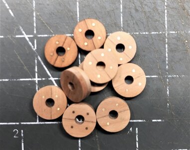
...and here are the trucks! They look perfectly round (actually they are) The bolting pattern is equally distributed on the track. I am happy with the result.
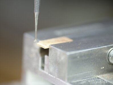
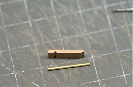
The next part for upgrade is the Stool Bed. It was made out of Pear with matching colors. First, both groves were made using the mill and round bur.
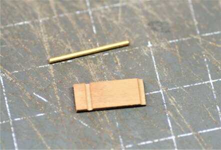
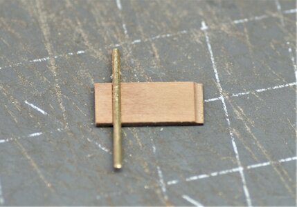
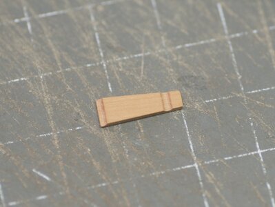
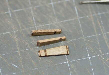
Below is the new (in the middle) and provided with the kit
This time I decided to use the carriage provided with the kit. Each bracket (left and right) was made in the upper and lower half. Besides the trucks, a major improvement was made on Ironwork.
The cap-square, already described, held the trunnions in place. The bolts which held the cup-square in position passed through both parts of the bracket, and also help to hold the fore axle in position. I use the kit-provided cap-squares, and the casting beautifully represents both bolts. Another bolt passed horizontally through the transom binding the brackets together. Here I made some bolts. This required to use of washers which I don't have ...so I made one!
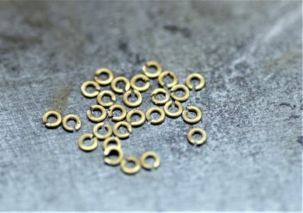
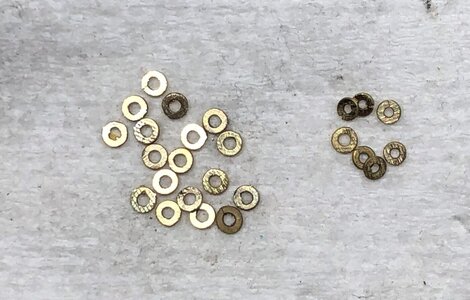
First, we will make some rings, the internal diameter must be a bit bigger than required. Using the jewelers saw we cut individual rings. The wire must be annealed to be very soft. Using the flat pliers close both ends to get a solid ring without gaps.
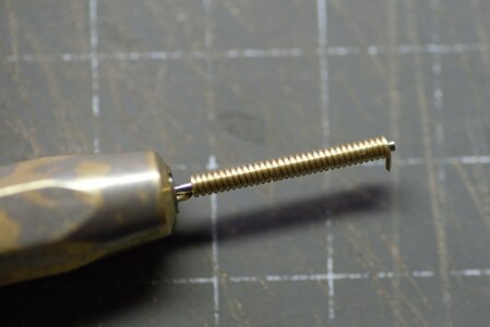
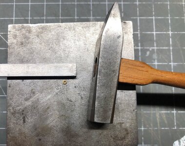
The next step is to flatten rings by topping each ring with the hummer until you have the desired thickness
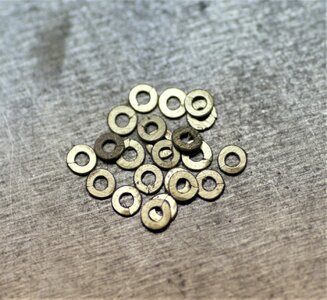
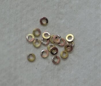
You may use them as is but, should you decide to make them more uniform and more presentable, you can solder the gap like in the photo below
To be continued tomorrow...thank you!
Today will be a short update from a previous post. Well..., I thought, I have finished with the cannons assembly overview, as declared quality 'out of the box' is dissent for the most part, but...something bothered me as incomplete and I thought about ways for improvement. So... here you go - Jim's way to improve the overall canon appearance.
I recall Triden Model told us that kit provided a solid base, and there are many ways for improvement. So I decided to improve the kit's cannons. One of the improvements made is in the canon trucks. Kit provided trucks as laser-cut, and the axletree hole was not round and perfectly centered. Obviously, you can make it round but this will require more sanding, and as the result, the trucks will be smaller than the required size. The second issue is the timber itself, it doesn't look good under oil, The material is very porous and soaks the oil like a sponge.
Original trucks were made from multiple timber pieces laminated and bolted together. Take a look at the images below.


The timber selection was easy, I cut the strips out of Pear and Castello just to see what would look better. Strips were glued together on the glass to make it perfectly flat and even.

Note two types of clamps: the metal clamps holding two strips together while glue sets, the plastic ones (blue color) holding the stips flat. The strips are only 1.5mm thick. Once the glue dry, using the tablesaw cut the strip assembly into the squares.

Now we will glue both squares together. Just make sure it is perfectly square (this is a 'must' for drilling the holes in the jig). Also watch out the line direction: both squares must form the 'plus + sign' e.g. on one side the line should be vertical, on another side it should be horizontal. I use machinist square to control the squareness


To make sure the glue evenly spread, I used the vise.

Time to drill the holes for bolt imitation. When repetition of similar work is involved, I always looking for jigs. A very simple jig was made to drill the holes, but this one ensures the holes were made on equal distance (assuming you have a perfect square). First, we will drill the axletree hole, because the diameter is the same for both hind fore axletrees.


Take a look at the above photo. There are two types of blanks: some of them for fore tracks, they will be larger than a hind truck, therefore the bolting pattern different. The next step in sequence - to make bolts. This time, I use brass wire 4.00mm, just insert the wire and cut flush on both sides. Time to make the wheels round. I use the wood lathe and turning chisel.


...and here are the trucks! They look perfectly round (actually they are)

The next part for upgrade is the Stool Bed. It was made out of Pear with matching colors. First, both groves were made using the mill and round bur.


Below is the new (in the middle) and provided with the kit

This time I decided to use the carriage provided with the kit. Each bracket (left and right) was made in the upper and lower half. Besides the trucks, a major improvement was made on Ironwork.
The cap-square, already described, held the trunnions in place. The bolts which held the cup-square in position passed through both parts of the bracket, and also help to hold the fore axle in position. I use the kit-provided cap-squares, and the casting beautifully represents both bolts. Another bolt passed horizontally through the transom binding the brackets together. Here I made some bolts. This required to use of washers which I don't have
First, we will make some rings, the internal diameter must be a bit bigger than required. Using the jewelers saw we cut individual rings. The wire must be annealed to be very soft. Using the flat pliers close both ends to get a solid ring without gaps.


The next step is to flatten rings by topping each ring with the hummer until you have the desired thickness


You may use them as is but, should you decide to make them more uniform and more presentable, you can solder the gap like in the photo below


To be continued tomorrow...thank you!
thank you for the clarification Wikipedia link about the series. I'll look at more closely now. RichHallo Jim,
maybe it is a good place to show the members also the review of this very helpfull book, especially for the modelers building this kit model of the HMS Alert
Book review - The Naval Cutter ALERT 1777 (Anatomy of the Ship)" by Peter Goodwin
Book Review: The Naval Cutter ALERT 1777 (Anatomy of the Ship) by Peter Goodwin Hardcover: 120 pages Publisher: Conway Maritime; Revised edition (April 19, 2004) Language: English ISBN-10: 0851779689 ISBN-13: 978-0851779683 Product Dimensions: 10.2 x 1 x 10.2 inches Shipping Weight: 1.7...shipsofscale.com
BTW Jim - Very good work on the gun carriages - very well done - and the kit is providing a very good basis to get such a result
Our forum is full of information.....thank you for the clarification Wikipedia link about the series. I'll look at more closely now. Rich
Book review - Anatomy of the Ship -> Series -> Ships with Sails
The books of the series "Anatomy of the Ship" is often a very important resource for the modeler of a kit or scratch. Here we want to list the existing books of this series, so you know which are available The 100-Gun Ship Victory by John McKay here we made already a Book Review, which you...
shipsofscale.com
Anatomy of the Ship -> Series -> Ships "after sail / modern"
The books of the series "Anatomy of the Ship" is often a very important resource for the modeler of a kit or scratch. Here we want to list the existing books of this series, so you know which are available The Aircraft Carrier Intrepid by John Arthur Roberts The Aircraft Carrier Victorious...
shipsofscale.com
Hallo Jim,
seems to be a very clever way with very good results - would be good to see this tutorial afterwards also in "Modelshipyard"
seems to be a very clever way with very good results - would be good to see this tutorial afterwards also in "Modelshipyard"
Many thanks for your 'likes' and valuable comments  I can't be happier!
...we shall continue with Ironworks from post #514
Earlier, we have identified the bolt passed horizontally through the 'Transom', binding the Brackets together. In our carriage, we will only imitate the bolt passed and making the bolt heads from both sides of the brackets. Another horizontal bolt passed between the brackets just behind the center of the carriage. This bolt also supported the Stool bed, which supported the Quoin.
We will use the washers, we made in the previous post. First, make necessary adjustments to the sickness and the inside diameter of the washer. The washer should go pretty tight on the rod designated as the bolt. This will ensure proper soldering and horizontal alignment. Yes, that's right, you guessed it right, we will solder the washer to the rod.
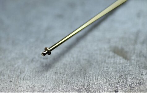
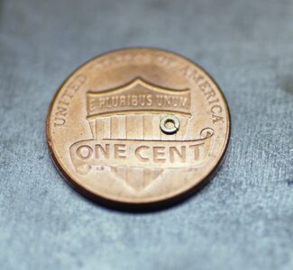
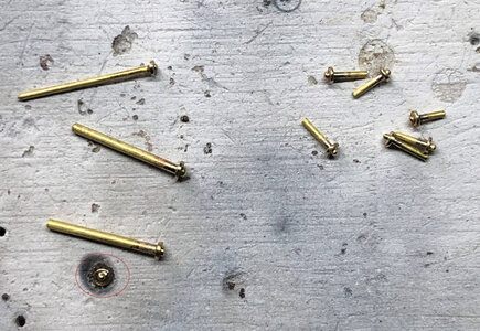
The head of the bolt should be a half-round shape (like a rivet's head). This can be done in few ways: before the washer soldering or after. I found, a better way to make the head after soldering the washer. The soldering piece can be further adjusted in the lathe or any rotary tool. For example, make the washer smaller\ perfectly round, and round the bolt's head. Just leave about 1.00mm from the washer, and using the round bur make a nice bolt's head.
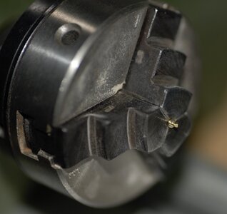
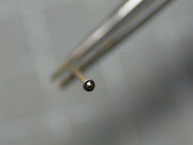
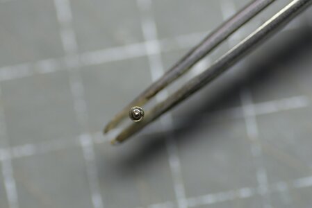
Unlike the first bolt, where we just imitate the heads, this bolt must be passed through both brackets as it will hold the Stool bed. This can be resolved by soldering only one side of the bolt. Another side just cut for the required size accounting for the sickness of the washer and rounded head. Then the washer will hold in place tight.
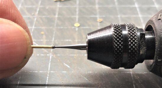
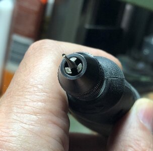
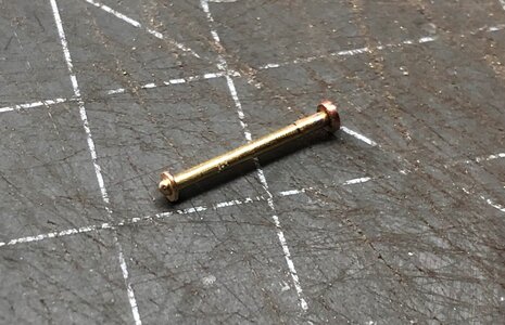
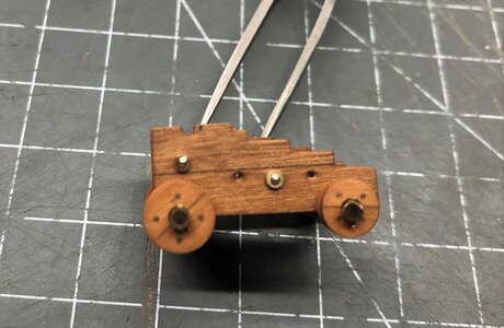
Two vertical bolts passed through both halves of each bracket and through the rear axles. I represent those bolts using the square brass wire. For this wire, you need to make the square holes. This was accomplished using the simple tool from the same stock of wire. The end was sharpened however as the chisel. In the predrilled holes insert this tool until you have the perfect square, that simple.
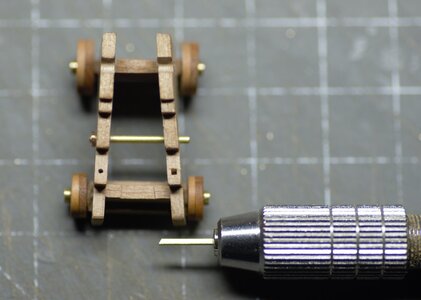
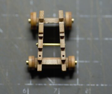
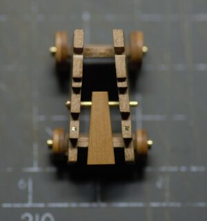
Alright, we are pretty much done implementing upgrades. The gun's breeching rope passed through a large eyebolt which was fitted on each side of the carriage, about halfway between the two trucks.
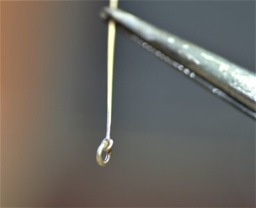
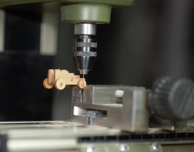
Some other improvements are the iron Axletree loop and Linch Pin. the loop was made using brass tubing with a suitable size. The Linchpins made out of leftover PE parts fret. The holes for linchpins made when the axletree already glued. This shouldn't be the way to drill the holes for the rest of the cannons. The proper way, however, is to make the holes first (before the assembly). Because this is POC (Proof Of Concept), I drilled the holes this way (ouch!!!!!)
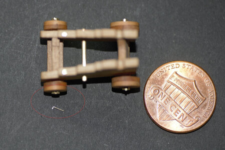
And here is the cartridge fully assembled with all improvements installed
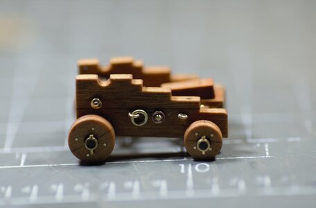
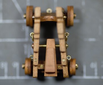
.... and the barrels installed, and supervisor makes the inspection... Hope he likes it!
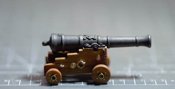
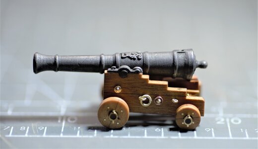
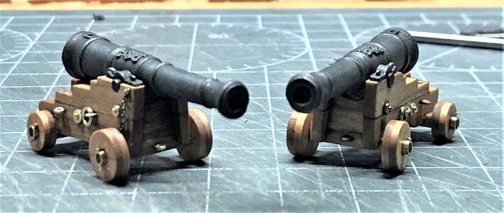
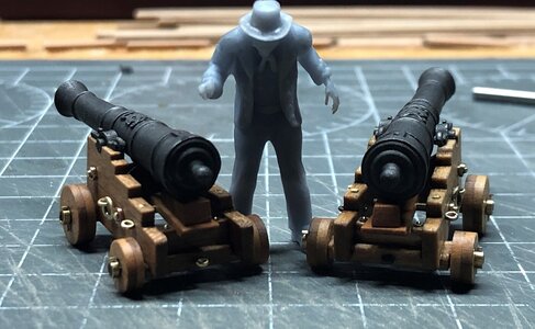
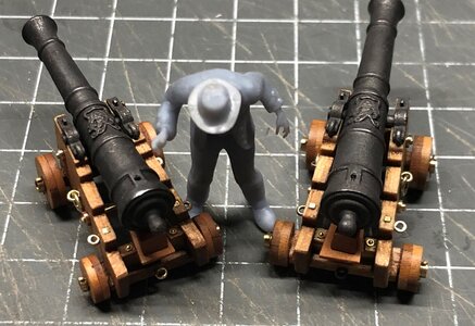
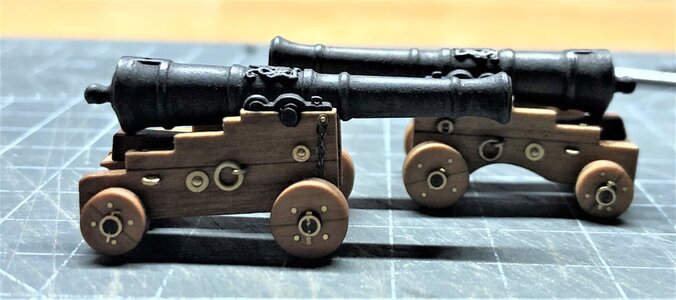
Well...with this, we reached the end of our cannon improvements. Hope you will find it useful for your builds... Thank you!
...we shall continue with Ironworks from post #514
Earlier, we have identified the bolt passed horizontally through the 'Transom', binding the Brackets together. In our carriage, we will only imitate the bolt passed and making the bolt heads from both sides of the brackets. Another horizontal bolt passed between the brackets just behind the center of the carriage. This bolt also supported the Stool bed, which supported the Quoin.
We will use the washers, we made in the previous post. First, make necessary adjustments to the sickness and the inside diameter of the washer. The washer should go pretty tight on the rod designated as the bolt. This will ensure proper soldering and horizontal alignment. Yes, that's right, you guessed it right, we will solder the washer to the rod.


The head of the bolt should be a half-round shape (like a rivet's head). This can be done in few ways: before the washer soldering or after. I found, a better way to make the head after soldering the washer. The soldering piece can be further adjusted in the lathe or any rotary tool. For example, make the washer smaller\ perfectly round, and round the bolt's head. Just leave about 1.00mm from the washer, and using the round bur make a nice bolt's head.


Unlike the first bolt, where we just imitate the heads, this bolt must be passed through both brackets as it will hold the Stool bed. This can be resolved by soldering only one side of the bolt. Another side just cut for the required size accounting for the sickness of the washer and rounded head. Then the washer will hold in place tight.


Two vertical bolts passed through both halves of each bracket and through the rear axles. I represent those bolts using the square brass wire. For this wire, you need to make the square holes. This was accomplished using the simple tool from the same stock of wire. The end was sharpened however as the chisel. In the predrilled holes insert this tool until you have the perfect square, that simple.


Alright, we are pretty much done implementing upgrades. The gun's breeching rope passed through a large eyebolt which was fitted on each side of the carriage, about halfway between the two trucks.

Some other improvements are the iron Axletree loop and Linch Pin. the loop was made using brass tubing with a suitable size. The Linchpins made out of leftover PE parts fret. The holes for linchpins made when the axletree already glued. This shouldn't be the way to drill the holes for the rest of the cannons. The proper way, however, is to make the holes first (before the assembly). Because this is POC (Proof Of Concept), I drilled the holes this way (ouch!!!!!)


And here is the cartridge fully assembled with all improvements installed


.... and the barrels installed, and supervisor makes the inspection... Hope he likes it!


Well...with this, we reached the end of our cannon improvements. Hope you will find it useful for your builds... Thank you!


