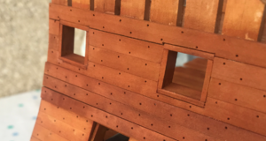
-

Win a Free Custom Engraved Brass Coin!!!
As a way to introduce our brass coins to the community, we will raffle off a free coin during the month of August. Follow link ABOVE for instructions for entering.
-

PRE-ORDER SHIPS IN SCALE TODAY!
The beloved Ships in Scale Magazine is back and charting a new course for 2026!
Discover new skills, new techniques, and new inspirations in every issue.
NOTE THAT OUR FIRST ISSUE WILL BE JAN/FEB 2026
You are using an out of date browser. It may not display this or other websites correctly.
You should upgrade or use an alternative browser.
You should upgrade or use an alternative browser.
USS BONHOMME RICHARD - POF - Cross Section in Pear - 1:48 - by Uwe
- Joined
- Mar 18, 2020
- Messages
- 36
- Points
- 93

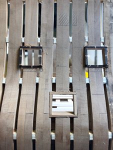
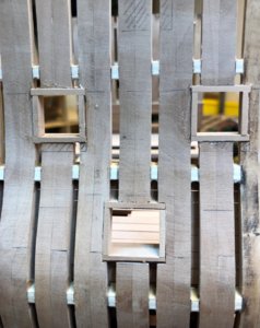
Today I tried the method with a adhesive foil on top of the planks like discussed in post #218 and #220, but unfortunately it was not working with this tape / foil.
With drilling through the tape I was not able to produce a round hole in the tape - maybe I have to try a different product
View attachment 138089
So I made it this time similar like before - drilling holes with a hand drill
View attachment 138090
filling with the woode-paste
View attachment 138091
after sanding the surface
View attachment 138092
It's a new way to simulate the nail head, and it's a good idea. Thank you
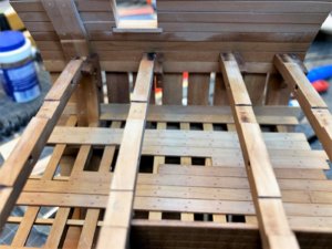
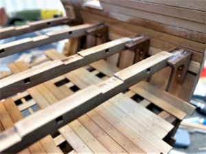
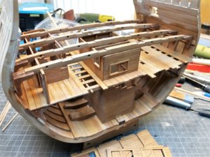
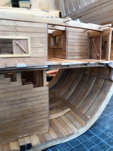
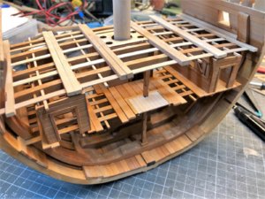
The installed second store room
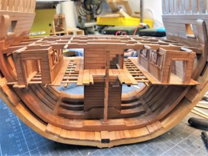
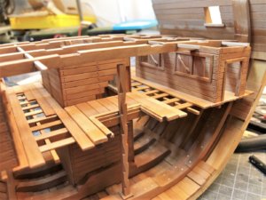
A little bit closer look on each side
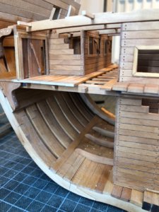
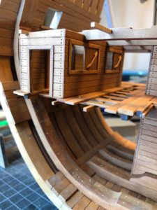
and the view from the other side
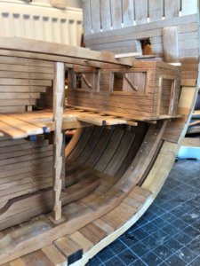
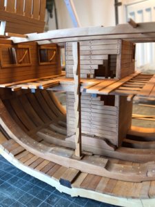
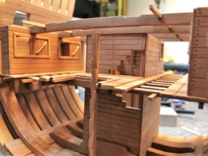
some nice closer views - a little bit like from seamen eyes
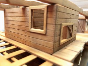
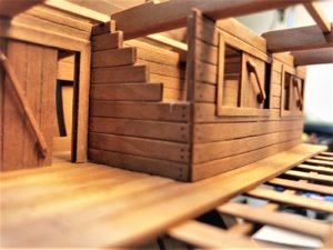
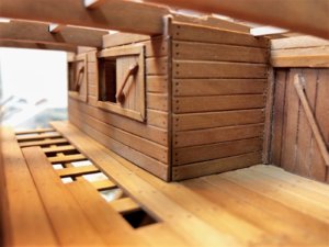
Unfortunately with these close-up photos you can see every grain of dust
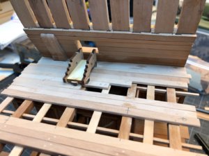
afterwards I dry-fitted the next elements of the deck with some fine-tuning that everything fits well for the next gluing session
Many Thanks for the interest ..... to be continued ......


A little bit closer look on each side


and the view from the other side


some nice closer views - a little bit like from seamen eyes


Unfortunately with these close-up photos you can see every grain of dust
afterwards I dry-fitted the next elements of the deck with some fine-tuning that everything fits well for the next gluing session

Many Thanks for the interest ..... to be continued ......
Hi.
Nice and clean work. Perfect!!!
Regards
Nice and clean work. Perfect!!!
Regards
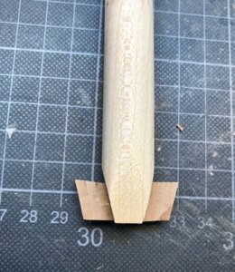
Yesterday I prepare the mast foot - and I am angry about myself, that I did it not before, when this area was better accessible..... But it is like it is.
The mast foot construction of the kit is much more simplified in comparison to the Boudriot drawings, nevertheless this detail of the footage was a common construction method and used in a lot of ships......
The kit
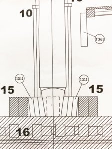
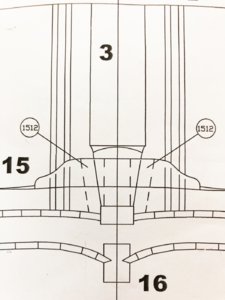
Boudriot
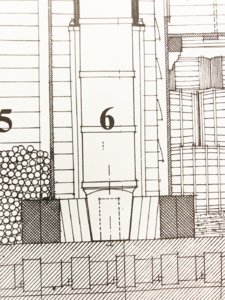
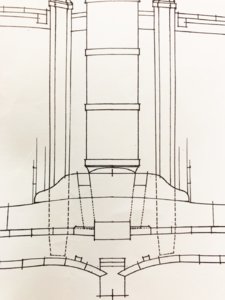
I have to prepare later on the mast form more in detail, but for now it will be ok, due to the fact that the mast by itself will be much later permanently installed
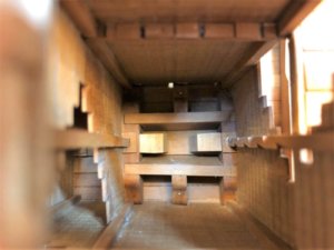
The view from the top into the pump room, visible are the two clamps to fix the mast foot
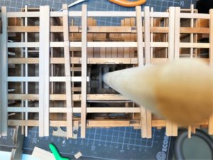
and a higher top view
The mast foot construction of the kit is much more simplified in comparison to the Boudriot drawings, nevertheless this detail of the footage was a common construction method and used in a lot of ships......
The kit


Boudriot


I have to prepare later on the mast form more in detail, but for now it will be ok, due to the fact that the mast by itself will be much later permanently installed

The view from the top into the pump room, visible are the two clamps to fix the mast foot

and a higher top view

It was time to start with the deck planking, but ...... the supervisor made an unexpected and unannounced inspection, so we had to stop the work for some hours until he checked the stability of all beams
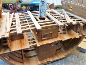
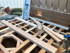
after some discussions we were allowed to go further with the planking
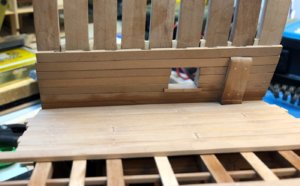
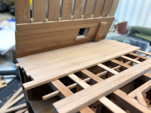
Tree-nailed in the usual way - just some smaller sanding of the surface is necessary I a can put the first gun on it
Sorry for the less photo quality - they were made this time with the mobile


after some discussions we were allowed to go further with the planking


Tree-nailed in the usual way - just some smaller sanding of the surface is necessary I a can put the first gun on it
Sorry for the less photo quality - they were made this time with the mobile
Just one point to watch Uwe,that is if you haven't thought of it already.Do not glue the collar of wedges to the deck.The mast has iron rings around it's lower section.If you glue the collar in place,the mast will not go through the hole with the iron bands fitted.
Kind Regards
Nigel
Kind Regards
Nigel
Many Thanks for the reminder - it is still only dry fitted and not permanently fixedJust one point to watch Uwe,that is if you haven't thought of it already.Do not glue the collar of wedges to the deck.The mast has iron rings around it's lower section.If you glue the collar in place,the mast will not go through the hole with the iron bands fitted.
Kind Regards
Nigel
In addition to the "normal" progress posts I decided to add also more often some descriptions with a comparison of some details between the kit design and the Bonhomme Richard drawings drawn by Jean Boudriot and published by ancre. Sometimes these differences are anomalies, simplifications or simply mistakes.
Today I want to show the cross section detail with the hanging knees etc.
Knees:
In the kit only wooden knees are foreseen, although the Bonhomme Richard had wooden knees only in the hold, on the other decks she had iron knees.
During her use by the french (Originally a French East-Indiaman Duc de Duras), the ship was a gunned merchantman and she had only one deck gunned, the other decks were reserved for transport and stowing.
Armed for protection against pirates in far eastern waters She carried her guns on one deck, twenty-eight 12-pounders, with six lighter pieces, six-pounders, on the poop-deck and forecastle.
Ports were cut in the gun room on the deck below where [John Paul Jones] mounted six 18-pounder guns.
Joints of frame elements:
The Z-formed joints of the frames were already discussed in older posts (post #10 and following) - this type of joint (Z) was never used by the french shipbuilders and is according my information a nice idea, but technically not realistic and correct.
Depth of frames:
Also the depth of the frames is changing much more from the keel to the top-timber.
Waterways:
Here the kit plan shows only a triangular stripe in addition to the deck-plank and one inside planking - usually the waterway is a part of the planking and made out of one piece.
Hull-planking:
The thickness of the planking of the real ship was slightly changing, due to the fact that she had no real wales, this was necessary to stiffen the ship structure longitudinal - the kit, but this is also done by most scratch modelers is using only using one thickness of planks (definitely for the inside planking)
On the left the kit drawing - on the right side Boudriot
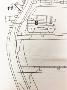
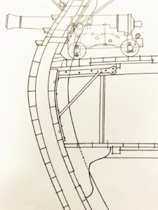


Hi
What a great job you are doing. The section is looking very nice. Fine and clean work.
Wanting to see more ...
Regards!!
What a great job you are doing. The section is looking very nice. Fine and clean work.
Wanting to see more ...
Regards!!
Many Thanks for your comment @carlosys - hope to see soon your progress on your section (so I can see how to make it  )
)
and all the likes received - much appreciated
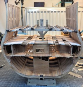
I started to prepare the bitts, which will be based on and against the main beams, so I know the areas to be cut from the deck planking
Also here I am still testing which areas I want to plank and which I want to keep open to see the structure
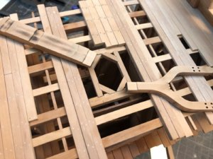
The bitts are not fixed - only to get an impression
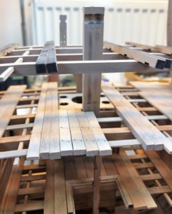
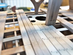
I started also the next level of beams and "carling"-beams - The bitts are fitting very well to the height of the new beams"
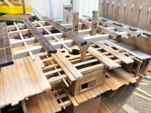
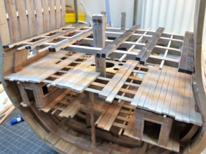
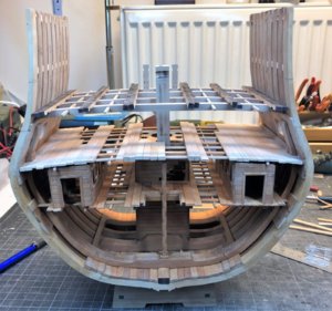
Many Thanks for your interest
and all the likes received - much appreciated
I started to prepare the bitts, which will be based on and against the main beams, so I know the areas to be cut from the deck planking
Also here I am still testing which areas I want to plank and which I want to keep open to see the structure

The bitts are not fixed - only to get an impression


I started also the next level of beams and "carling"-beams - The bitts are fitting very well to the height of the new beams"


Many Thanks for your interest
hi
This is how you have to approach construction. Go ahead to anticipate possible mistakes. So there are no unpleasant surprises.
I would also like to see your work in advance, I will wait for you to advance. So I can copy you
Yesterday I updated my thread.
Regards
This is how you have to approach construction. Go ahead to anticipate possible mistakes. So there are no unpleasant surprises.
I would also like to see your work in advance, I will wait for you to advance. So I can copy you

Yesterday I updated my thread.

Regards
Many Thanks for the comments and likes...... Thanks
Next step was the opening of the next level of gunports - before I started the saw, I thought to control once more the pencil marks I made some months ago - I had some doubts, especially comparing with the level of the beams and the height of the deck
And indeed - they were wrong - so I remeasured twice and three times and corrected them before I started to cut the frames
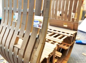
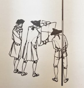
Off course the supervisors found very fast the responsible person - The guilty person / the culprit is only UWE
If you need some advice from them, they are not available and sitting in the Pub and drinking beer
and if there is an error they only discuss who is guilty - Typical behaviour
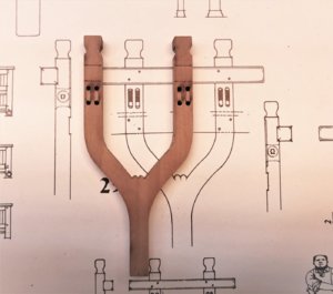
In addition I made some smaller fine-tuning of the bitts, also comparing with the Boudriot drawings (which are helping a lot!!!)
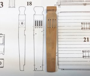
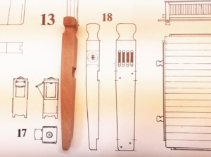
Many Thanks for your interest .... to be continued ....
Next step was the opening of the next level of gunports - before I started the saw, I thought to control once more the pencil marks I made some months ago - I had some doubts, especially comparing with the level of the beams and the height of the deck
And indeed - they were wrong - so I remeasured twice and three times and corrected them before I started to cut the frames

Off course the supervisors found very fast the responsible person - The guilty person / the culprit is only UWE
If you need some advice from them, they are not available and sitting in the Pub and drinking beer
and if there is an error they only discuss who is guilty - Typical behaviour

In addition I made some smaller fine-tuning of the bitts, also comparing with the Boudriot drawings (which are helping a lot!!!)


Many Thanks for your interest .... to be continued ....
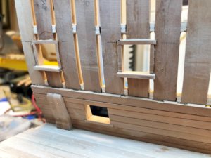
I was able to finalize the framing of the gunports on one side
Also here we can find a difference between the kit design and the original (and correct) technique.
Both have the upper and lower cills which form the horizontal framing. The cills are based / founded in some small notches of the frames futtocks.
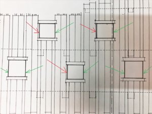
The gunports are usually located directly at one double frame, so that the vertical sides are the futtocks (green arrows), only sometimes, when the gunport would end in the space between two frames, additional vertical timbers were necessary (red arrows)
Here the Boudriot drawing:
This is the kit solution, I guess they developer of the kit took the imperfection of the modeler into account - f.e. G14, G23, G24, G16 and G04 would be usually not necessary
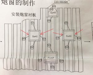
I mentioned it - the imperfection of the modeler - so I installed the vertical sides also
final sanding only when I am at the stage of the planking work
Many Thanks for the interest
Also here we can find a difference between the kit design and the original (and correct) technique.
Both have the upper and lower cills which form the horizontal framing. The cills are based / founded in some small notches of the frames futtocks.
The gunports are usually located directly at one double frame, so that the vertical sides are the futtocks (green arrows), only sometimes, when the gunport would end in the space between two frames, additional vertical timbers were necessary (red arrows)
Here the Boudriot drawing:

This is the kit solution, I guess they developer of the kit took the imperfection of the modeler into account - f.e. G14, G23, G24, G16 and G04 would be usually not necessary

I mentioned it - the imperfection of the modeler - so I installed the vertical sides also

final sanding only when I am at the stage of the planking work


Many Thanks for the interest
Many Thanks for the comment and the Likes .... much appreciated .....
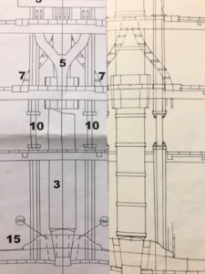
Yesterday I made the wooden blocks around the mast (sorry I do not know the english term) which are fixing the mast towards the first level of beams.
First of all a small comparison of the kit solution and the Boudriot drawings - one the left the kit and on the right Boudriot - Boudriot shows the logical and technical necessity, that the blocks have under the deck a smaller thickness, otherwise it was not possible to hit them down, when fixing the mast.
also in this area I want to show the structure of the beams, so I opened the planking, but the blocks around the mast should be complete
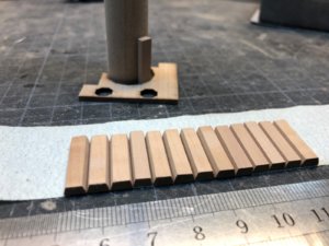
so I prepared the total number of blocks and fixed them on a sticky tape - in the background you can see the mast with one block
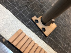
in the gaps I filled the wooden glue and formed the tape with blocks around the mast, in order to get the correct diameter
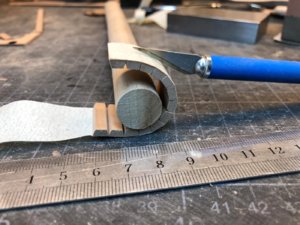
fixed
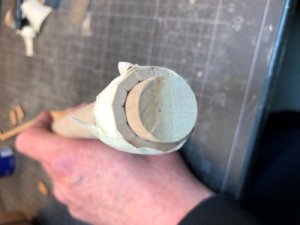
with dry glue I was able to remove the tape
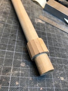
now I was able to start to give the ring the correct final form
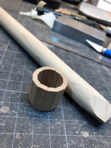
comparing with the Boudriot drawing
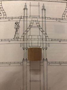
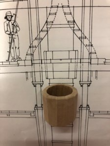
it is still on the wrong height, but you can imagine how it is looking like
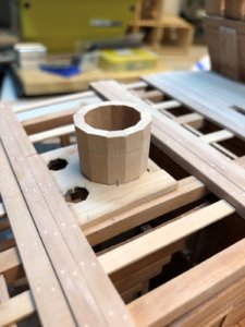
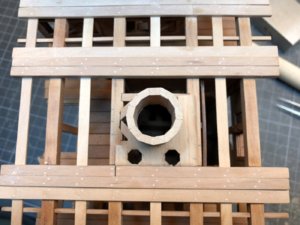
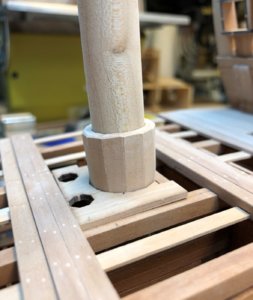
I forgot also to make the small end of the beam and added this one cutting one small dovetail groove
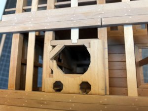
Many Thanks for your interest .....
Yesterday I made the wooden blocks around the mast (sorry I do not know the english term) which are fixing the mast towards the first level of beams.
First of all a small comparison of the kit solution and the Boudriot drawings - one the left the kit and on the right Boudriot - Boudriot shows the logical and technical necessity, that the blocks have under the deck a smaller thickness, otherwise it was not possible to hit them down, when fixing the mast.

also in this area I want to show the structure of the beams, so I opened the planking, but the blocks around the mast should be complete
so I prepared the total number of blocks and fixed them on a sticky tape - in the background you can see the mast with one block


in the gaps I filled the wooden glue and formed the tape with blocks around the mast, in order to get the correct diameter

fixed

with dry glue I was able to remove the tape

now I was able to start to give the ring the correct final form

comparing with the Boudriot drawing


it is still on the wrong height, but you can imagine how it is looking like


I forgot also to make the small end of the beam and added this one cutting one small dovetail groove

Many Thanks for your interest .....


