USS BONHOMME RICHARD - POF - Cross Section in Pear - 1:48 - by Uwe

I do have Longridge's Anatomy of Nelson's Ships, and it has an excellent detail of the main mast, with sections and details along every part of it. But I didn't know if it would apply to a smaller, French ship.
Definitely the french had also the needs to construct the mast with different timbers. they did not have bigger or thicker trees ;)
I am not aware, if they had maybe different ways of connecting the elements, so if the cross section was different.
I know, that over the time and better knowledge and experience, the elements of masts changed......
Definietly it is a nice add on and an interesting detail of a model
 
Very interesting:

The Elements and Practice of Rigging and Seamanship

MAST-MAKING.-Vol. I.


The Elements and Practice of Rigging And Seamanship, 1794, by David Steel, is a comprehensive English textbook of rigging, seamanship and naval tactics. A key reference for those interested in the age of Nelson. Although at times difficult because of its fine detail, it will reward those that search through it to understand the technology of the era.The fonts in the 1794 original created unusual challenges to its conversion from images to text. Its s, f, S, F and l characters are not easily distinguished. Even in reprint, this is an expensive book and so we used photography rather than flatbed scanning to capture the document. Finally, each of the copies we had available had faded pages. All of this is to explain that even after quite a lot of work, this manual required more proof-reading and correction than any we have previously attempted. We really appreciate your reporting any errors that you find. We would especially like to thank Scott Weller for his thorough and accurate 2011 proofreading and reporting.Please note that the page numbers in the tables jump from 138 to 141. This accurately reflects the 1794 original and the reprint from a different original.In this online version of the manual we have attempted to keep the flavour of the original layout while taking advantage of the Web’s universal accessibility. Different browsers and fonts will cause the text to move, but the text will remain roughly where it is in the original manual. We have not attempted to correct any errors found in the original document. However, this text was captured by optical character recognition and then encoded for the Web which has added new errors we wish to correct. We wish to thank United States Naval Academy Museum for letting us photograph an original of the 1794 manuscript. Thank you also to San Francisco Maritime National Historical Park‘s J. Porter Shaw Library for the access to a reprint of this manual. Finally, we wish to acknowledge Sim Comfort Associates for creating the really nice 1978 reprint. Please report any typos, or particularly annoying layout issues with the Mail Feedback Form for correction. Richard Pekelney Webmaster


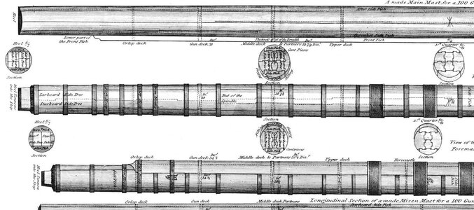
Drawings at the end ....

mast of a 100 gunner

Mast 2.JPG


mast of a 74 gunner:

mast 1.JPG

 
Here you can see a typical sketch / drawing
and the pattern sheet element 19C2 which is one front element of the magazin in the hold. They are included not as a basis for gluing the planking (laser cut strips also in photo) - really only as a pattern. If you plan not to show the back size of the wall, you can easily use these pattern also as a base and directly glue the planks on top. But I want to partly open the magazins (you will see this later in a photo) it is necessary, that these pattern sheets are not visible.

View attachment 129421

It is maybe not possible to see very well - it is my first attempt with a folio over the pattern sheet, so that the planks will be not glued against the pattern sheet - But it was not working (for me) - so a failed try
View attachment 129422
When I first looked through the kit, the way these boards are made (laser cut out of a sheet), I assumed that they were meant to be applied in one piece, with the spacing of the boards retained. That is, apply a sheet with all boards to the structural members, then cut off the extra, so there are slight spaces (laser cuts) between the boards. But you have removed them and applied them separately, which is probably more realistic.

My question is: If the builder had intended them to be separated, why wouldn't they have just been furnished as stripwood?

 
Very interesting indeed. Two things surprise me:

Up to 13 pieces of wood in one section at the 3/4 section for the main mast?? Wow, that is a LOT of work, considered they're coaked on all side not on the outside? Again, wow!

Secondly, the section shown, in large part, is not circular. The Front Fish, added at (or almost at) the foot of the mast, in this case adds a entire offset arc portion, adding considerably to the section of the mast. Makes it like 2 circles smashed together, probably adding 8" or so to the total diameter at the upper portions. I don't recall that used elsewhere, or on model ships, although it may be very obvious when complete.

Lastly, I notice throughout that document references to the royal navy. Would these documents also apply to French ships, like the Duc de Duras? And the cross-section I've seen for the HMS Victory is significantly different than this.
 
When I first looked through the kit, the way these boards are made (laser cut out of a sheet), I assumed that they were meant to be applied in one piece, with the spacing of the boards retained. That is, apply a sheet with all boards to the structural members, then cut off the extra, so there are slight spaces (laser cuts) between the boards. But you have removed them and applied them separately, which is probably more realistic.

My question is: If the builder had intended them to be separated, why wouldn't they have just been furnished as stripwood?
Good question - could be also done with strip wood.
The interior sheets are part of the add ons, which you can buy in addition or optional. Therefore these elements have to be packed extra and separate to the normal kit. If the manufacturer would choose strip wood, he would have a long pieces, which have to be packed, so therefore it would be much more complicated to store and send by post.
With making them out of a laser cut sheet, it is a small package and much easier to handle.
 
Very interesting indeed. Two things surprise me:

Up to 13 pieces of wood in one section at the 3/4 section for the main mast?? Wow, that is a LOT of work, considered they're coaked on all side not on the outside? Again, wow!

Secondly, the section shown, in large part, is not circular. The Front Fish, added at (or almost at) the foot of the mast, in this case adds a entire offset arc portion, adding considerably to the section of the mast. Makes it like 2 circles smashed together, probably adding 8" or so to the total diameter at the upper portions. I don't recall that used elsewhere, or on model ships, although it may be very obvious when complete.

Lastly, I notice throughout that document references to the royal navy. Would these documents also apply to French ships, like the Duc de Duras? And the cross-section I've seen for the HMS Victory is significantly different than this.
should be researched in coimparing in detail the cross section of a french with a english or other navies masts ..... I do not know in moment
 
Nice work Uwe! I am enjoying your build, even if I am late to the party. I still plan on updating my builds soon!?!
Hallo Shane,
mayn thanks for your kind words about my work on the Bonhomme section.
She is still unfinished, and in the meantime the model received also a layer of saw dust by the othe rmodels built.
I think I will need another 100 or 150 hours or so to finalize the model, so maybe in between ......
Hope to see also your updates soon .....
 
Back
Top