
-

SUBSCRIBE TO SHIPS IN SCALE TODAY!
The beloved Ships in Scale Magazine is back and charting a new course for 2026!
Discover new skills, new techniques, and new inspirations in every issue.
NOTE THAT OUR NEXT ISSUE WILL BE July/August 2026 -

Win a Free Custom Engraved Brass Coin!!!
As a way to introduce our brass coins to the community, we will raffle off a free coin during the month of August. Follow link ABOVE for instructions for entering.


You are using an out of date browser. It may not display this or other websites correctly.
You should upgrade or use an alternative browser.
You should upgrade or use an alternative browser.
USS Constitution - Model Shipways (kitbashed) 1:76.8 by GGibson




Thanks, Jon! Is this where I say "Hold my beer!"? I've already struggled in a few areas and am sure to hit several more walls in this phase. Fortunately, I've got you guys to follow who have led the path for me. You are all appreciated!Most builders struggle with the transom, myself included. You seemed to breeze right through it even while deviating from the plans to create the six window 1812 version. Well done!
Jon


Ah, this takes me back to the good old days. Go back to my build log - "Book 1", starting with page 148 of 198, to see my notes (and complaints about the Hunt practicum) on this part of the build. I think you are very close to turning the ship upside down to plank to the keel. I noticed you didn't leave the three openings in the transom at the stern rail, so assume you will be cutting these out after planking (or focusing on a different year in Conny's history where these don't exist(?).
Next up will be the counter pieces. What fun you'll have with those! The flip Conny 180 degrees and prepare to spend the next month or more planking, planking, planking...
Enjoy your hiatus, wherever that may be.
Next up will be the counter pieces. What fun you'll have with those! The flip Conny 180 degrees and prepare to spend the next month or more planking, planking, planking...
Enjoy your hiatus, wherever that may be.
I noticed you didn't leave the three openings in the transom at the stern rail, so assume you will be cutting these out after planking (or focusing on a different year in Conny's history where these don't exist(?).
Thanks for the peek-in and info, Peter! And I appreciate the reminder of your transom work in your build log. I have looked at it again. And, yes, it's that "counter extension" piece that I have been pondering.
For my "1812-ish" goal, the Hull model's stern did not have the openings at the spar deck level. This is (hopefully) what I am shooting for.
Thanks again for the comments and info.



Good morning Greg. Quality work- lovely progress. Cheers Grant
Thank you, Grant! Appreciate the look-in!Good morning Greg. Quality work- lovely progress. Cheers Grant
It looks like, before I shape and position the lower block that will rest against the knuckle portion of the transom and will be the base of the quarter galleries (on both sides) that I must complete before I am able to complete the transom planking, I need to plank the main wale area where all these other parts will rest against.I will now need to continue the transom planking between and on both sides of the windows, and then down across the counter piece. It appears, though, that maybe before that, I need to shape a block that will rest against the “knuckle” portion of the transom. That block creates what will be the bottom portion of the quarter galleries. Does that process sound correct to those who have gone through this?
I am getting closer to the point of turning the ship over to continue the lower hull planking and begin the coppering. Well, at least I think I’m getting closer…
So… to position these main wale planks, it was best that I turn the ship over! I guess this is one of those major construction milestones to remember. Some time ago, to prepare for when I would have this ship upside down for the planking and coppering, I purchased a long roll of 3" thick foam for the ship to rest on. I think this will work well!
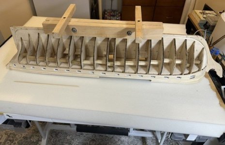
The plan instructions call for this main wale area to have seven 3/32” thick planks that are tapered to 1/16” thick at each end. So, these planking strips will be made from 3/32” x 3/32” square basswood strips. The first row laid pretty easily with no difficult shaping at the stern end for this first one, but I needed to hold a strip under hot water for a bit in order to form the planking on the bow end. Will probably have to do that on both stern and bow as I continue with the next six main wale planks.
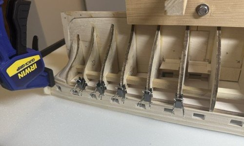
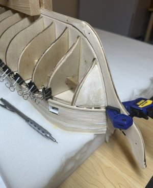
Hopefully, this all will go well. Heading out for a brief trip the first of the week. Will continue where I leave off upon my return and then work on those quarter gallery base blocks and the lower transom planking. I appreciate all of the follows, likes, comments and criticisms!
How are you managing to taper the planks?
Just sanding what visually appears as a natural taper down to 1/16". Starting about an inch back. At scale, that would be about 6 feet. Seems about right.How are you managing to taper the planks?
Wow, hard to believe it took me two weeks to work on the remainder of these port-side main wales strakes. But, in my defense, I did take an awesome 5-day trip to the Black Hills in South Dakota in between, so I have a bit of an excuse.
I left off starting on the main wales area of my Constitution and had laid one strake of the 3/32” square plank strips. All of the strips laid fairly well from bow to stern, tapering them at each end down to 1/16” thick. I did have to continue to hold each of the strips that ended at the bow under a hot water stream to help with the curve shaping.
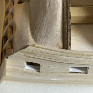
Finishing these thicker main wale strakes at the stern were a bit of a challenge and it appears that, in reviewing all the other build logs, several of my fellow builders had similar concerns with how to properly finish these strakes at this end.
The way my 6th and 7th strakes were laying, they ended up tucked back behind the 5th strake as they ended against where the transom counter will reside. After these were placed, I sanded the corner of this transom area and I think it will come out nicely. Not sure yet, though, how the quarter gallery will affect this.
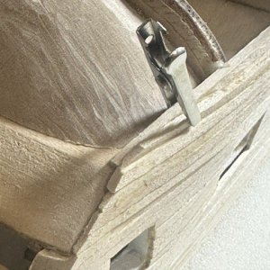
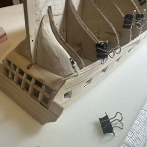
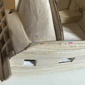
So, the port-side main wales are complete. Will now spin it to the starboard side and do those, as well.
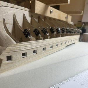
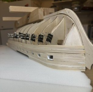
Appreciate the reads, the follows, the comments and the critiques.
I left off starting on the main wales area of my Constitution and had laid one strake of the 3/32” square plank strips. All of the strips laid fairly well from bow to stern, tapering them at each end down to 1/16” thick. I did have to continue to hold each of the strips that ended at the bow under a hot water stream to help with the curve shaping.
Finishing these thicker main wale strakes at the stern were a bit of a challenge and it appears that, in reviewing all the other build logs, several of my fellow builders had similar concerns with how to properly finish these strakes at this end.
The way my 6th and 7th strakes were laying, they ended up tucked back behind the 5th strake as they ended against where the transom counter will reside. After these were placed, I sanded the corner of this transom area and I think it will come out nicely. Not sure yet, though, how the quarter gallery will affect this.
So, the port-side main wales are complete. Will now spin it to the starboard side and do those, as well.
Appreciate the reads, the follows, the comments and the critiques.
A very quick update… After completing the port side main wales, I spun the ship around and worked on the seven wales planks on the starboard side. The work went like what I experienced on the port side, with each of the 3/32” square plank strakes going down well. Like the port side, the 6th and 7th strakes tucked behind the 5th strake against fill piece and counter block.
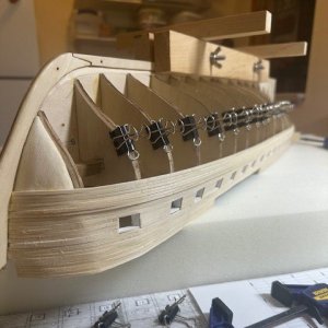
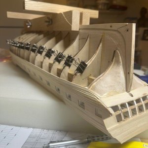
While I am getting closer to planking the lower hull now, it appears I should first finish planking the stern transom and counter piece and also start working on the base of the quarter galleries. The base fairing block and bottom block of the quarter galleries will provide a solid foundation for the counter planking to butt against.
So… that’s next on the list! I told you it was a very quick update! Appreciate, as always, the reads, follows, comments and critiques.
While I am getting closer to planking the lower hull now, it appears I should first finish planking the stern transom and counter piece and also start working on the base of the quarter galleries. The base fairing block and bottom block of the quarter galleries will provide a solid foundation for the counter planking to butt against.
So… that’s next on the list! I told you it was a very quick update! Appreciate, as always, the reads, follows, comments and critiques.
Gregg, At this point, while the keel and bulkheads are exposed, you might want to think about how your model will be displayed when done. If you plan on pedestals, you might want to consider provisions as to how they are to be attached to the keel. I have strong pins which pass through the keel into the pedestals, but allow the model to be easily removed from them if necessary. Other builders have theirs screwed permanently to the keel which may require you to re-enforce those support points. If on the other hand if you plan on using a cradle...well never mind, you're all set.
Jon
Jon
Jon brings up an excellent point. In perfect 20/20 hindsight, I wish I'd made provisions for thick posts in the keel.Gregg, At this point, while the keel and bulkheads are exposed, you might want to think about how your model will be displayed when done. If you plan on pedestals, you might want to consider provisions as to how they are to be attached to the keel.
Jon
If you plan on pedestals, you might want to consider provisions as to how they are to be attached to the keel. I have strong pins which pass through the keel into the pedestals, but allow the model to be easily removed from them if necessary.
Jon & Peter, I appreciate the advice on how my Constitution will eventually be displayed. And you will be happy to know that, early on in my build way back in July 2025 as I was first starting this build, I heeded your advice then, Jon, as you had demonstrated in your build log that I had reviewed, and I placed the two support holes about 12” apart, approximately at the F & N bulkhead locations.Jon brings up an excellent point. In perfect 20/20 hindsight, I wish I'd made provisions for thick posts in the keel.
Using just a pin vise and drilling holes by hand, I had to accurately drill straight down through the rabbet and keel in order to insert a 3/32” tube at each spot. I started with a #60 micro drill bit and carefully worked my way up through larger drill bits so as to not tear out the hole. So, a #60 drill bit, then a #54, then a #50, then 5/64”, then finally a 3/32” bit so that I could tap in the small tubes.
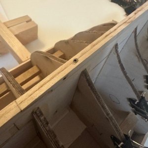
So, I am prepared for a pedestal display. I do like, though, some of the cradle displays, as well. Actually, I've been thinking of making a cradle that would still have the pins in the base that would slide into these tubes. But that's one of those "We'll cross that bridge..." items.
Anyway, I appreciate the heads-up, Jon! And also Peter's support, as well. I'm sure I'll need more guidance as I work on these quarter gallery foundations.
Thanks, gentlemen!
I had completely forgotten you had followed by lead. I do look at a lot of logs, so forgive me for my lapse. Sometimes, I'm surprised when someone actually follows what I did, after all, I still consider myself a newbie as this is only my second wooden square rigged ship. I feel my expertise in wooden model building is still in the learning stage.
I'm glad you thought ahead, and I hope this display method works out...for both of us!
Jon
I'm glad you thought ahead, and I hope this display method works out...for both of us!
Jon
Another probably quick lil update… I traced the plans for the small counter extension piece and cut the wood for it. Placed and glued it in its position on both sides of the stern frame.
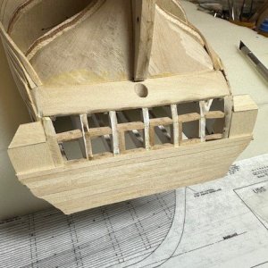
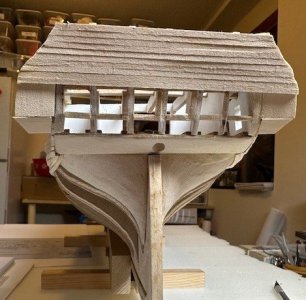
I then began working on the base bottom block for the quarter galleries. Once again, I traced the plans for the bottom blocks. These bottom blocks are cut from 1/4” stock. The bottom sides of these blocks are smaller than the top side.
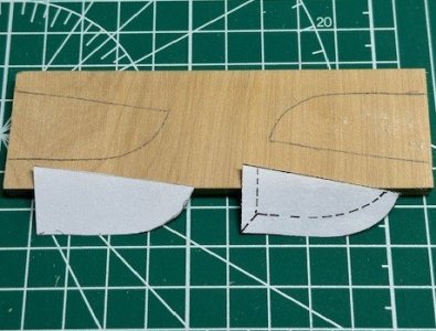
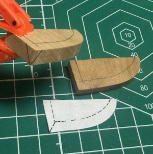
In order to taper these down to the dotted lines, I used my Proxxon disc sander, which made quick work of the shaping necessary for these blocks.

Except that, when I was done with the tracing, cutting, sanding and shaping, I quickly realized that I had made two identical blocks, both shaped for the port side. Ooops!
Ok, so I cut another 1/ 4” stock piece and this time shaped it for the starboard side. I now have the two bottom blocks needed as a base for the quarter galleries.
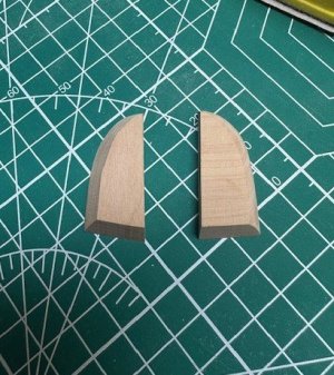
These blocks were shaped to the exact shape and angles as shown on the plans. However, when I place them in their positions butted against the counter extension piece, there is a gap. The backside of the bottom blocks need to be angled more.
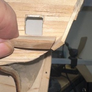
If these bottom blocks were cut and shaped exactly as planned, that would mean the counter piece is placed incorrectly. But that would not have given the proper angle coming off the stern transom. I think I’m good with where I’ve got everything. I am just going to sand the angle a little bit more on the bottom blocks so they fit well against their counter piece extensions and call it good. I think I’ll be okay. If anyone has objections and alternate advice, please let me know!
I then began working on the base bottom block for the quarter galleries. Once again, I traced the plans for the bottom blocks. These bottom blocks are cut from 1/4” stock. The bottom sides of these blocks are smaller than the top side.
In order to taper these down to the dotted lines, I used my Proxxon disc sander, which made quick work of the shaping necessary for these blocks.
Except that, when I was done with the tracing, cutting, sanding and shaping, I quickly realized that I had made two identical blocks, both shaped for the port side. Ooops!
Ok, so I cut another 1/ 4” stock piece and this time shaped it for the starboard side. I now have the two bottom blocks needed as a base for the quarter galleries.
These blocks were shaped to the exact shape and angles as shown on the plans. However, when I place them in their positions butted against the counter extension piece, there is a gap. The backside of the bottom blocks need to be angled more.
If these bottom blocks were cut and shaped exactly as planned, that would mean the counter piece is placed incorrectly. But that would not have given the proper angle coming off the stern transom. I think I’m good with where I’ve got everything. I am just going to sand the angle a little bit more on the bottom blocks so they fit well against their counter piece extensions and call it good. I think I’ll be okay. If anyone has objections and alternate advice, please let me know!
Be careful with the sanding. By sanding the block angle for a better fit aft, you are moving the forward end aft as well and may end up being short further on in the build. Check for the consequences of your adjustments. An alternative is to just add a filler block in the gap between the transom and the filler block.
Jon
Jon
Be careful with the sanding. By sanding the block angle for a better fit aft, you are moving the forward end aft as well and may end up being short further on in the build. Check for the consequences of your adjustments. An alternative is to just add a filler block in the gap between the transom and the filler block.
Jon
Excellent point, Jon, which I was also considering the consequences and looking for feedback, which you provided. I was thinking I had read there was a certain prescribed distance between the front edge of this bottom block and the back corner of the last gunport that's located in the Commodore's cabin. Let me try to find that reference again. If that's the case, I may just decide to make completely new blocks, which would be easier than getting an exact sized filler block. I have plenty of 1/4" thick stock. Appreciate the feedback!
Ha! True! Forgot that this area will be covered. Well, except that my Commodore may fall through the crack when, umm, having his "morning constitutional".That gap will cover over by planking, so you might not need to fill it at all.
Jon
