USS Constitution MS2040

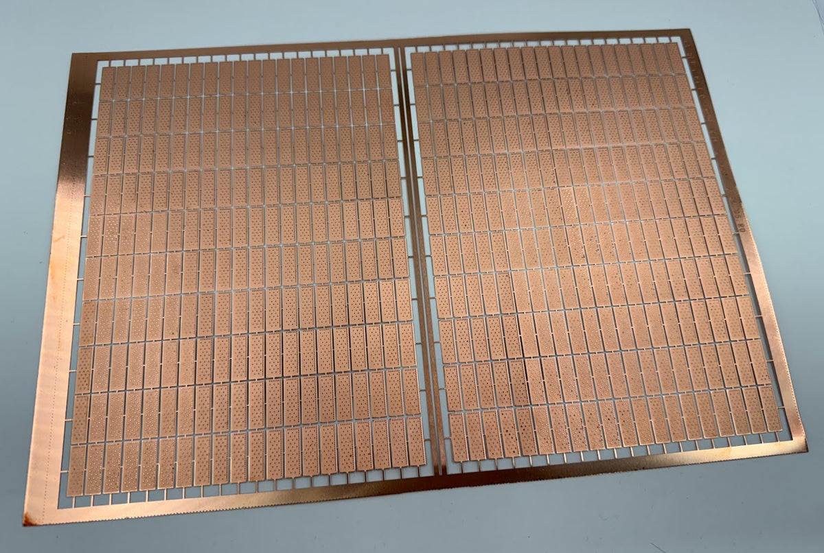
Jack, Model Expo has some copper plates already done and are detailed. Not like the tape that comes with box.
6 x 12 mm

7 x 18

I was thinking of this myself, but I have not done the math scale and I am not sure if these will do.
--------------------------------------------------------------------------

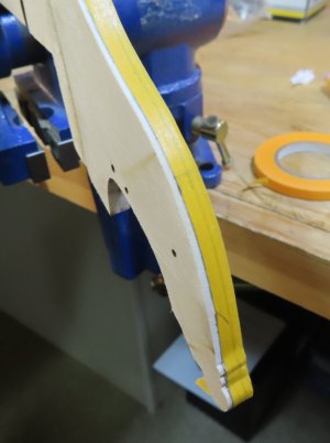
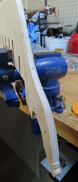
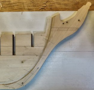
So, I am now laying out the Tapering Lines for the Stem and Sternpost.


frame17.jpg


frame18.jpg


frame19.jpg


IMPORTANT:
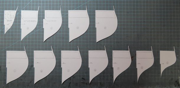
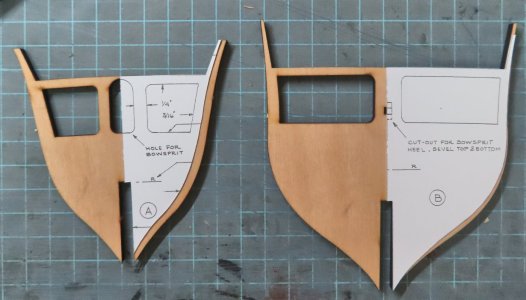
The following image shows that I copied the Bulkheads and used spray adhesive to attach them to card stock. Then, as seen, I cut out one half of the Bulkhead. The most important feature of this step is that if you go to plan sheet #1, you will see that on one side of the Bulkhead drawings is another "LINE" that represents the "FAIRING" line.

In these "Templates", I cut along the LINE of the FAIRING. When the Templates are laid on top of each Bulkhead, a pencil line will be drawn onto the section that will be sanded, cut, or filed down. Then the Template will be turned to the other side of the Bulkhead and repeated.

Also, note that the REFERENCE lines will also be transferred to Bulkhead. To repeat, on the right side of each Bulkhead, there are TWO lines drawn. One is the out-most Edge and the inner Edge (Fairing line). The outmost edges have been cut away !!!


frame20.jpg
 
Last edited:
Jack, Model Expo has some copper plates already done and are detailed. Not like the tape that comes with box.
6 x 12 mm

7 x 18

I was thinking of this myself, but I have not done the math scale and I am not sure if these will do.
--------------------------------------------------------------------------

So, I am now laying out the Tapering Lines for the Stem and Sternpost.

View attachment 479505


View attachment 479506


View attachment 479507


IMPORTANT:
The following image shows that I copied the Bulkheads and used spray adhesive to attach them to card stock. Then, as seen, I cut out one half of the Bulkhead. The most important feature of this step is that if you go to plan sheet #1, you will see that on one side of the Bulkhead drawings is another "LINE" that represents the "FAIRING" line.

In these "Templates", I cut along the LINE of the FAIRING. When the Templates are laid on top of each Bulkhead, a pencil line will be drawn onto the section that will be sanded, cut, or filed down. Then the Template will be turned to the other side of the Bulkhead and repeated.

Also, note that the REFERENCE lines will also be transferred to Bulkhead. To repeat, on the right side of each Bulkhead, there are TWO lines drawn. One is the out-most Edge and the inner Edge (Fairing line). The outmost edges have been cut away !!!

View attachment 479508

Another great build.
Kive your prep work .

model expo copper tiles looks very bulky.
I can recommend you to use caldercraft ones they are looking better.
Amati raised their prices for the copper tiles.

Good luck with the build.
 
Another great build.
Kive your prep work .

model expo copper tiles looks very bulky.
I can recommend you to use caldercraft ones they are looking better.
Amati raised their prices for the copper tiles.

Good luck with the build.
I am not sure how many packs I will need. I guess I can call the ship half a cylinder and use that to approximate the surface area...+ 10% contingency
 
Well , if I did my math correctly I get around 3000 tiles plus 10%(300) which is 3300 tiles or 66 packs. I cannot justify this cost. Even if I say, only need half of that, it still is quite expensive. So no tiles for me.
 
Last edited:
@Jack Sparrow Interesting - I did not know that Dry Dock carried those. The size should also work well to.


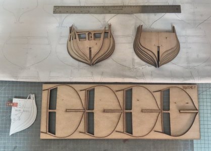
Onward to the marking of the Fairing lines. The templates were made from photo copy of the plans (copying machine at home). Transfered the Fairing lines to the Bulkheads using a Pencil. Also marked the Reference line in the center.

The first photo just shows an example of the marking. The templates do not line up "precisely" but taking into consideration, I still went by the plans to make sure the markings were done correctly. The absolute center of hulls Bulkheads do not get any fairing done.


frame22.jpg


frame21.jpg
 
Last edited:
@Jack Sparrow Interesting - I did not know that Dry Dock carried those. The size should also work well to.


Onward to the marking of the Fairing lines. The templates were made from photo copy of the plans (copying machine at home). Transfered the Fairing lines to the Bulkheads using a Pencil. Also marked the Reference line in the center.

The first photo just shows an example of the marking. The templates do not line up "precisely" but taking into consideration, I still went by the plans to make sure the markings were done correctly. The absolute center of hulls Bulkheads do not get any fairing done.

View attachment 479734


View attachment 479735
Dear Donnie
you are doing wonderful work as always, I will keep following with great curiosity
good luck my friend :) Thumbsup
 
I am starting the glue up.

NOTE: Please see post 43 and 44 before you start bulkhead glue ups.

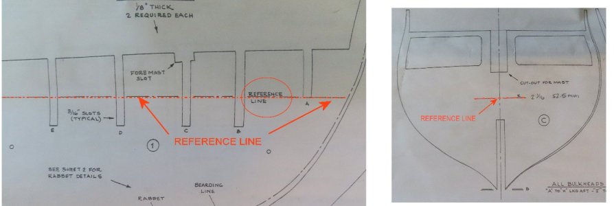
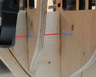
NOTE: It is essential to establish your REFERENCE LINE on the KEEL and EACH Bulkhead. You should use these lines to MATCH the tick marks. DO NOT use the slots. If you use the slots (as in pushing your Bulkhead all the way that both are touching, i.e.) then you will have a discrepancy of each Bulkhead height !!!

When you use the Reference Lines to match the tick marks, you will notice that some NOTCHES in the KEEL and Bulkead either do not MEET or need to be filed down - either case - DO NOT use the slots - use the Reference Lines (taken from the plans).

The Reference Line is STRAIGHT on the KEEL and not curved. It is the Bulkheads (Reference lines) that will make the Bulkhead TOPS have a slight curve along the Profile View.

frame23.jpg


frame24.jpg
 
Last edited:
I am starting the glue up.

NOTE: It is essential to establish your REFERENCE LINE on the KEEL and EACH Bulkhead. You should use these lines to MATCH the tick marks. DO NOT use the slots. If you use the slots (as in pushing your Bulkhead all the way that both are touching, i.e.) then you will have a discrepancy of each Bulkhead height !!!

When you use the Reference Lines to match the tick marks, you will notice that some NOTCHES in the KEEL and Bulkead either do not MEET or need to be filed down - either case - DO NOT use the slots - use the Reference Lines (taken from the plans).

The Reference Line is STRAIGHT on the KEEL and not curved. It is the Bulkheads (Reference lines) that will make the Bulkhead TOPS have a slight curve along the Profile View.

View attachment 481213


View attachment 481214
agreed. I found this part of the build to be a bit of a nightmare. It was surprising to see how off some of those slots were. Also, if you don't use the reference lines, the bulkheads will not align properly with the bearding line.
 
Back
Top