Ok. Thank you.Hi John,
I googled for the drawing and it is mentioned on this one.
View attachment 125381
There you would say both are in line with each other.

-

SUBSCRIBE TO SHIPS IN SCALE TODAY!
The beloved Ships in Scale Magazine is back and charting a new course for 2026!
Discover new skills, new techniques, and new inspirations in every issue.
NOTE THAT OUR NEXT ISSUE WILL BE July/August 2026 -

Win a Free Custom Engraved Brass Coin!!!
As a way to introduce our brass coins to the community, we will raffle off a free coin during the month of August. Follow link ABOVE for instructions for entering.
You are using an out of date browser. It may not display this or other websites correctly.
You should upgrade or use an alternative browser.
You should upgrade or use an alternative browser.
USS Constitution - very old Mamoli kit - by first time builder - build log
- Thread starter JohnB163
- Start date
- Watchers 21
-
- Tags
- constitution mamoli
It looks like part 32 is slightly below frame one.Ok. Thank you.
Attachments
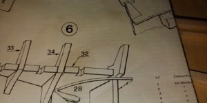
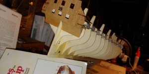
Part 28 is supposed to go under part 32, by mine doesn't. I need to figure out how to pull it down. There is nothing I can glue it to in order to get it under. I will keep working to figure out something. This whole project is both fun and frustrating.It looks like part 32 is slightly below frame one.

Part 28 on your model is in the correct location. Part 32 has to be moved above part 28. You can see the ears on part 1 just above part 28 in the photo you posted above. Part 32 should be glued above those ears where it attaches to part 1.
Just above the false deck in this photo you can see the shadow on part 1 of what I am calling the ears. The bottom of part 32 should basically match the location of the top of part 28 in this photo. Not the other way around. Hopefully that makes sense.

Just above the false deck in this photo you can see the shadow on part 1 of what I am calling the ears. The bottom of part 32 should basically match the location of the top of part 28 in this photo. Not the other way around. Hopefully that makes sense.
Last edited:


I know it’s not the answer you want to hear. But nothing comes out perfect. There are always slight changes that have to be made to bring it together. True it is either the kit or the builder. If it’s the builder, hopefully we catch our mistake and learn from it.
Looks good!
Looks good!
How viewIn order to have the stem to align properly I have to add relatively large spacers as shown in the attached images. I am know working on the stern.View attachment 125637View attachment 125638View attachment 125639View attachment 125640View attachment 125641


Does it mean around each window in order to make a frame?Confused..
Step 4 Last sentence."before assembly, glue some paper strips along the cutting lines linking the small windows (figure 9).View attachment 125818View attachment 125820

My kit contains 1700 green pieces of wood that are to be add to simulate copper plates. After gluing each of these then I have to paint each copper. In another Group someone mentioned that there was a copper tape that could be substituted for the 1700 green plates. Unfortunately, I did not get the ordering information. Is anyone familiar with any possible substitute for the 1700 pieces.

Take a look at this very good tutorial, maybe this is an alternative solution for youMy kit contains 1700 green pieces of wood that are to be add to simulate copper plates. After gluing each of these then I have to paint each copper. In another Group someone mentioned that there was a copper tape that could be substituted for the 1700 green plates. Unfortunately, I did not get the ordering information. Is anyone familiar with any possible substitute for the 1700 pieces.
from:
Navy Board Models
Attachments
You are rolling through this build! Looking good my friend. This string has definitely helped me with my build!!
Thank you very much.Take a look at this very good tutorial, maybe this is an alternative solution for you
from:
Navy Board Models
navyboardmodels.com
John,
I think you need to make a change before it's too late. Took me a while but just figured out a way to add arrows etc to a photo is why I didn't do this earlier.
You need to make an adjustment to part 32. If you look at the green arrows below part 32 needs to be adjusted to where the green solid box is on part 1. The planking goes under the green solid box where the blue arrow is. Also I'm guessing part 32 will lay flat or very close to flat the stem where the red arrow is. This will put part 32 above part 28 like I was trying to explain in post #64.
Last edited:
Thank you. I am in the process of un-gluing part 32.John,
I think you need to make a change before it's too late. Took me a while but just figured out a way to add arrows etc to a photo is why I didn't do this earlier.
You need to make an adjustment to part 32. If you look at the green arrows below part 32 needs to be adjusted to where the green solid box is on part 1. The planking goes under the green solid box where the blue arrow is. Also I'm guessing part 32 will lay flat or very close to flat the stem where the red arrow is. This will put part 32 above part 28 like I was trying to explain in post #64.
Here are some photos of the metal gun ports. Notice the the first two and last two on both sides are almost parallel to the desk. The others have a slanted configuration, but the bottom is roughly parallel to the deck. I hope this is correct. I have loosened parts 32, 33, 34. I will now try to re-install so that part 32 is above the false deck. I appreciate the help I have received.


.
.