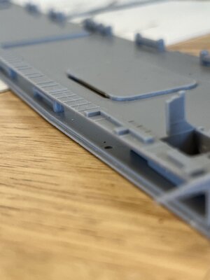
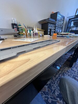
USS Gambier Bay (CVE -73) 1/350 by Hasegawa with Hasegawa photo etch [COMPLETED BUILD]

Joined
May 22, 2022
Messages
520
Points
308

Location
Broomfield, Colorado
I while back I discovered the Gambier Bay reading about the Samar battle. More specifically I was researching the USS Johnston DD-557 heroic efforts while a member of Taffy3 comprised of 6 escort aircraft carriers guarding the landings against a large Japanese fleet. The battle was massive in that it turned around the Japanese fleet trying to disrupt the Leyte invasion of the Philippines. I could go on about the the battle of Samar but you'd get more information googling USS Johnston and USS Gambier Bay. The more I read the more I wanted to do something part of this battle. The Johnston was a Fletcher class destroyer and there are some many Fletchers built or being built I wanted something a little unique. I haven't seen anyone build the Gambier Bay so that was it for me. Part of the taffy 3 and lost during the battle and plenty of historical information available.
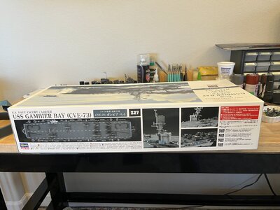
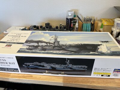
The box arrives March 9, 2023 now the wait to finish current build
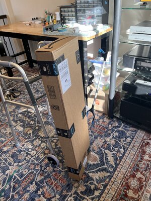
39C6D952-F9C5-4427-843F-BBF9047446EC.jpeg

Of course I had to open checking for damage or missing parts. DUH!!!!!
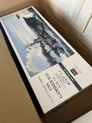
FC10E0D0-61F0-46DE-AF2C-52A28D8B29F2.jpeg5643219E-6C3A-4CA5-AF5B-74A662598890.jpeg3B5A3965-CB20-4268-A8AB-1396197D0365.jpeg
No packaging damage now inside to the parts.
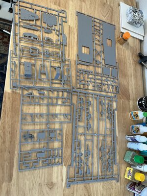
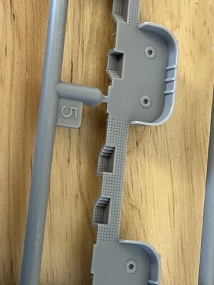
First sprue no broken or missing parts. Hasegawa did a fantastic job with the mold no flash no seams really sharp square corners. Only comment is the no skid plates are too bold for the scale but being mostly out of sight its no big issue.
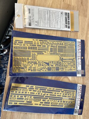
First was to look at the photo etch sheets
D786EB80-8000-48EA-8280-36A613A749C8.jpeg
I did open the wooden deck. It really looks amazing but will be a huge challenge to get it right.
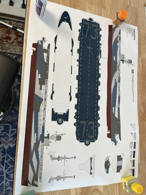
This is a full size poster that came with it for painting and building.
74EBCB94-F95B-4977-A594-B3359F3C1961.jpeg
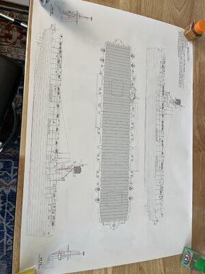
That camouflage pattern is going to be a massive undertaking as each side is different. Starboard being straight lines and port being curved lines. Oh boy what fun!! The back side is for building
E8D5CB67-3E74-4DBB-B803-3992E893C770.jpeg
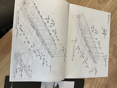
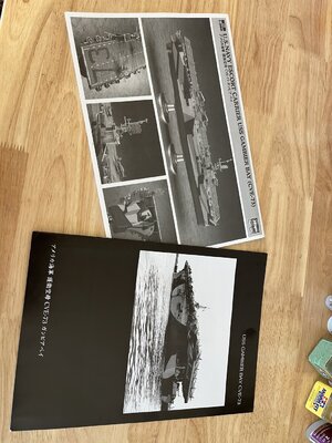
The books one being in Japanese but luckily the last two pages are english. My daughter just got a minor in Japanese maybe I can get her to translate. The instruction manual is printed in landscape, not a problem just unusual. Maybe a leftover for Japanese printing. Next a phot of instructions which seem very clear to understand.
28542B2E-12E1-4EA8-850A-43114E38D8E0.jpeg91A03B30-81F1-41F9-A86C-434789C1BC20.jpeg
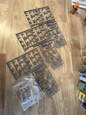
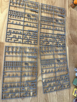
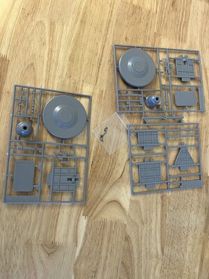
The following are photos of each sprue which, I hope, show the quality of the injection molds.
ADD6543E-331C-4ED4-A46D-BB29825A4457.jpegB8AB78BC-2B3B-4241-B520-74C3EC22D41A.jpegB8AB78BC-2B3B-4241-B520-74C3EC22D41A.jpeg
7D527617-63A2-4752-B86D-1190BD7C7297.jpeg0CD5CD26-ACB3-46A4-AC14-8BC797F398E7.jpeg9887F368-C7BD-48D7-BEF1-7E2DF33D00D6.jpeg438E050E-D75A-4D76-A330-82C88F495686.jpegA874E2F5-A782-4237-B0A0-6CF8F6B02709.jpeg
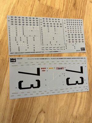
Lots of airplanes and that means more decals.

Tomorrow on page one
 
Read a good book about the Gambier Bay. The Men of the Gambier Bay by Edwin Hoyt. Amazing story.
Looks very tempting to do this model myself!
 
By Heck! Someone has got his work cut out for the foreseeable!.

Looking forward to watching this develop. Thumbsup
 
Interesting model - I am looking forward to see your progress
 
Issue #1 of the Gambier Bay Build.
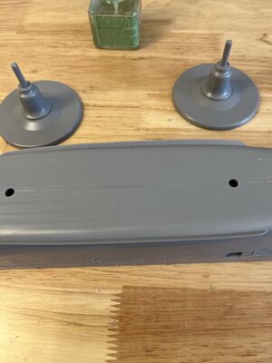
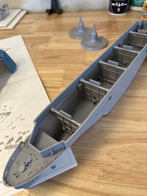
Started with the hull as described in the plans. First thing was to make the display stand holes. Inside the hulls were half circles about half the material thickness indicating were to finish the holes. You can see the half circle below bulkhead #3
EC33F563-2C84-423B-B9B1-B7DA1DA51C6C.jpeg
Closeup of roughed in hole
2BC5A789-C024-4FCD-8E4B-E5A63D765B93.jpeg
Next was assemble the halves into a hull and complete the mounting holes. Picture shows the bulkheads with the alignment pins molded in place.
4C0E0FA1-14B9-4082-BBEA-8B2817578C0E.jpeg
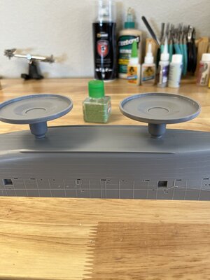
Here is the hull glued together with the mounted hole completed and stands in place.
FB752A3B-7316-4D74-A267-687FC8A4D62A.jpegCEFC5656-3E52-4BD5-8649-4C52A4FC8852.jpeg
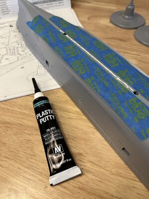
After lunch time to get back to the shipyard. With the glue set the halves together there was a slight opening that needed some plastic filler. Squeezed some filler along the seam at the keel. This was the first time I used a youtube method of filling the seam from another modeler. The hull has very nice panel lines and I didn't want to damage them by sanding. Placing the painters tape along the molded panel line to protect them from aggressive sanding.
3DB01974-9637-4907-B202-400DFAD53C47.jpeg
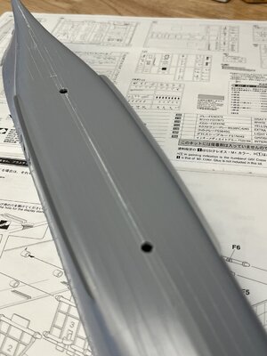
Finished seam and the panel lines left undisturbed
66EE2529-9AD6-4E58-A7C4-B8D374BFBFDD.jpeg
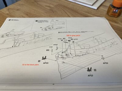
Now on to the bow and stern decks. If I follow the instructions I'd be placing painting parts before painting the camouflage which would require masking the previously painted parts. Duh I think I paint the hull and add the camouflage before adding things like anchors, hose reels, etc.
Picture shows instructions added painted parts before the main paint
DB7BB7CA-7D8D-4DBE-B1DA-85F4264B7C6B_1_201_a.jpeg
That's about all the time I have for today so pictures show status\17F1C86B-298C-421A-A0D5-628701A7314C.jpeg21498FEF-10C2-4DE1-B0F3-8B47A6DB9090.jpeg

So far I'm very pleased with Hasegawa kits. I have noticed the plastic seems harder than say Tamiya or Academy plastic. I'm not sure what is better but just an observation. One thing that is a little troubling is the connectors from the part to the sprue are much larger than from previous models. Not a problem, it just requires more cleanup because of the larger and harder connection.
 
I am sure you will have great fun with this.

One thing I have found to be helpful is to put weight in the hull. The ships are so light that it is easy to disturb them from where ever you want them to be. I use epoxy and place either BBs or fishing weights in the hull to give it a slight heft.
 
I picked up a trove of material from the estate of the chief engineer of one of her sister ships. Including a chunk of a 14" Japanese shell that struck her. "The Last Stand of the Tin Can Sailors." It was an astounding event.
 
I want to thank everyone for the comments and likes, Thank You. Rob444 thanks for the heads up on weight. I had noticed the hull being tall before the deck it felt light and now that you mention it top heavy. Since I'm building this out of the box and only including the Hasegawa photo etch specifically for the Gambier Bay I want to show some comparison part pictures.
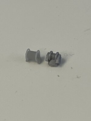
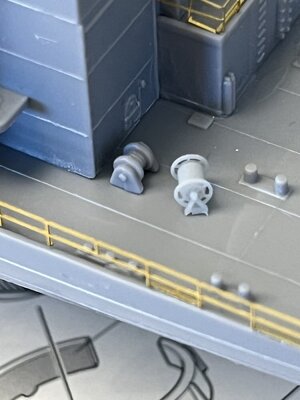
This is a 3d printed hose reel alongside the model molded hose reel
39684C3E-0B2C-4CF9-BC12-A48425D41B92.jpeg
The differences are obvious and the decision was hard but I'm staying with the original plan and make it out of the box.
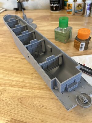
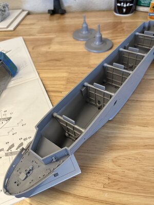
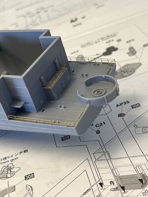
The front and aft decks have been installed along with associated mounted parts. My plan is to paint the grey and then add the flat black where its called for. It was time for some pe railing along the decks. The last thing was to add the propeller shafts and rudder.
fore deck
21498FEF-10C2-4DE1-B0F3-8B47A6DB9090.jpeg
Aft deck with pe railings
BF472F17-3155-48F1-A4E1-74FD159D1F8E.jpeg

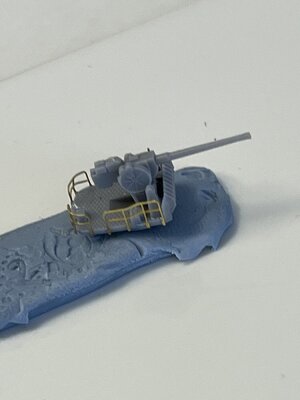
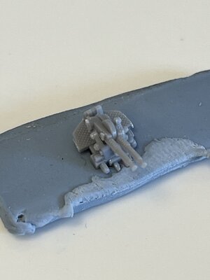
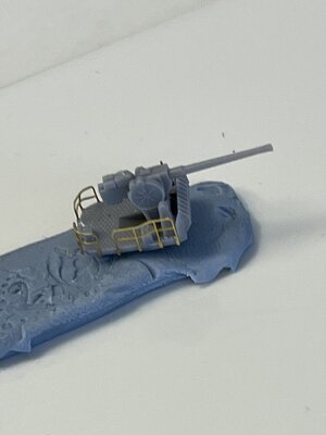
Next on the list are the aa guns. First thing is the 5" stern mounted gun here again more decisions had to be made. The pe set has many small (did I has small I meant really really small) parts that could be added to the guns. My past experience is people looking at my models nobody sees the tiny details just what jumps out to them so I decided to forego the tiniest details.
5" gun with just railings
4BBD94B9-23A5-44D4-98EE-D8189C36B4FB.jpeg
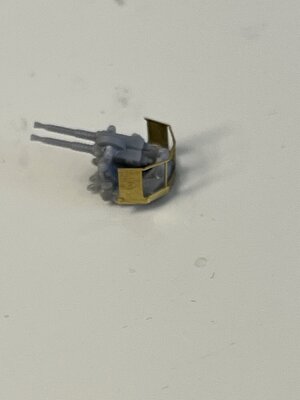
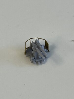
twin 40mm bofors
F6CAB58C-8876-4D5B-846D-1DE7EBE5C37E.jpeg
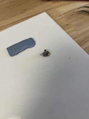
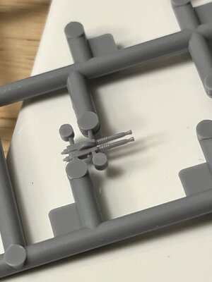
The 20 mm guns as so small that it might be impossible for me to attach all the pe so they will be made out of the box with no enhancement.

79B4AE6E-F677-4E2F-9C82-9A85732AD3B3.jpeg

3B2AEC21-00F7-4C98-8006-7E339BC9426D.jpeg

3EAA4A43-1449-4708-A23B-F2ABF8B82ABD.jpeg
 
Thank you Davidp, but this is what I was dealt with in the Hasesgawa kit.
B3CD9DA5-C095-49BF-96E7-275D4D04E9F2.jpeg
So based on my decision to build out of the box and not use 3d printed enhancements such as the 3d-wild offering, I'll proceed as planned. Thanks for the info that will come in handy in future builds.
 
Again a big thank you to Davidp for his insight on my twin 40mm bofors. His input made me go back and look at how I had assembled the twin 40mm bofors. The large hump Davidp had referenced was actually the bottom of the barrels. It was a very long and difficult process to remove the barrels from the mounting without damaging either. Most of yesterday spent cutting and removing the barrels and then reassembling the mounts. The other comment Davidp brought up was that barrel spacing being too wide and verified by the web document he referenced, but there is no fix for this as the mold cannot by modified.

With all the rework done I thought I'd show comparison pictures of the mounts.
Barrels in the incorrect position
4BBD94B9-23A5-44D4-98EE-D8189C36B4FB.jpeg

Barrels installed correctly
1FD10EF7-AFCA-4804-BA6F-21DB2D256F61.jpeg
 
no problem but i think your 1st picture is supposed to be the twin barrel 40mm mount not the 5" 38cal gun mount.
 
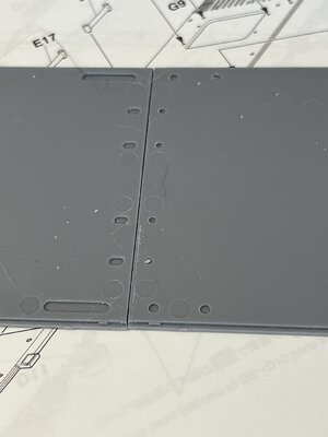
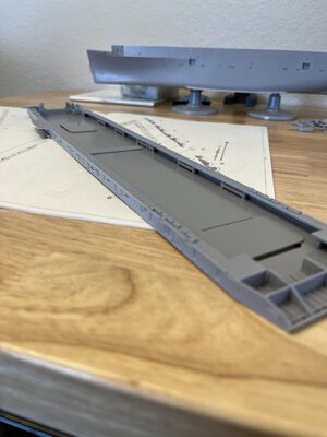
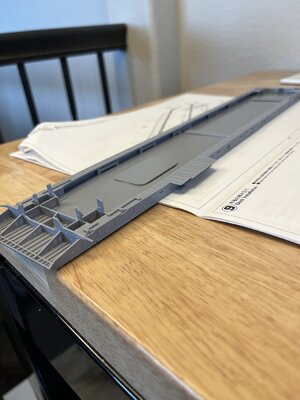
Finished the eight 40mm bofors and twenty 20mm guns and no onto the decks. When the decks were dry aligned I noticed that a small gap was left no matter how hard pushed together.
DBA1EBBA-FDF9-4B28-88F3-9709D14D30ED.jpeg

Some light filing brought them into alignment.
54DF457F-D0A3-4CF9-B21D-AB64A10A57F7.jpeg
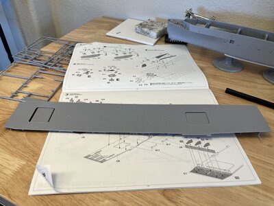
I had already placed the elevator door backing pieces to the decks before squaring the deck. Next the iron work supporting the deck overhang. The forward pieces were quite fiddly removing the tabs and then the slotted parts did not completely engage. To keep everything tight and square I folded a piece of 400 grit sandpaper running it the the slots. Making a trial fit between strokes. When a fit together it dropped perfectly into position.
Forward supports
718B9C47-6DC0-4E1A-A44A-E4A5D2D142B5.jpeg

Aft supports were definitely easier to build and place.
17AE2DB1-B881-490E-AC20-D16620A9857C.jpeg
I placed these odd looking pieces per the plans. Wondering how they fit into the assembly but I'm following the plans so have to wait until next step.
 
have you tried dry fitting the flight deck to the hull to see if those 2 odd looking pieces interfered the sitting of the flight deck onto the hull?
 
Thanks Davidp for you thought but yes I did the trial fit and the funny pieces do not interfere. I looked ahead in the manual and now see that the parts support some of the side to be added in the next step.
Thanks taking the time to consider my project.
 
no problem. i have the Booklet of General Plans for CVE-90 USS Thetis Bay of the Casablanca Class & could not find those weird shape pieces in the plans.
 
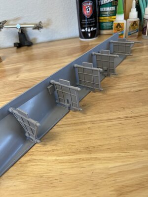
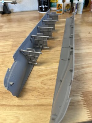
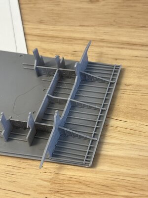
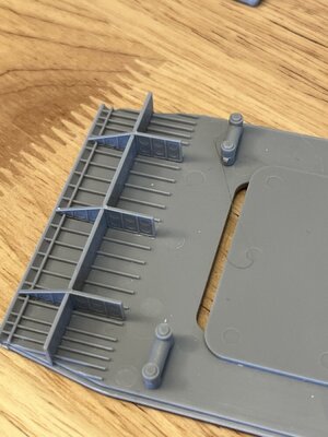
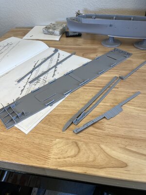
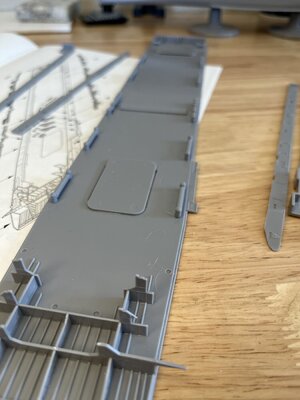
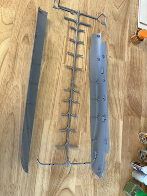
A lot of work getting the deck and the and gallery bulkheads assembled. Started with removing the parts from the sprue and cleaning the edges of stubs.
D4A02FD5-E87F-4A64-9CFB-81439E97F47F.jpeg

I then carefully tacked the inside pieces that attach to the funny tube looking parts.
Here you can see the tubular parts in question
36B4B658-0957-4CCD-AEB7-3C1D1884075B.jpeg

I now added the bottom of the gallery deck resting on the tubes keeping in in position. The tubular parts have a small raised circular pad that intersects with gallery part assuring correct alignment. Very cleaver.
A546EB6B-4F4E-4B74-B5F6-E4D582D47FDD.jpeg
This picture shows the slots and tabs for alignment along with the tubular parts7AAF4CEF-6DE8-4155-B4AF-AD9E06695BB6.jpeg

The gallery deck sides were very easy to install due to the designers thinking. There is a relief the sides fit into and tabs that align with slots on the adjacent parts.770DD350-68E3-4368-9072-541426ECE327.jpeg0D902FCE-FB5F-4924-8BF2-5C2A0522654A.jpeg

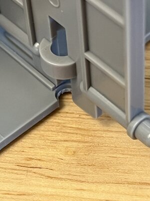
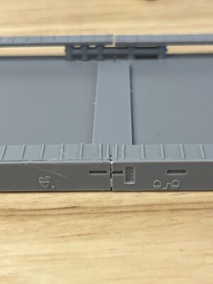
All fit as designed but a problem was where the parts joined. A small gap was left on the bottom and side of the gallery deck which will need attention. Not sure how to fix this 1) putty will work but since any small amount of flex will break the putty 2) Should I put a small piece of styrene glued into the gap and then finish with small filler. Have to think this through and also see if this area will be visible.
3F7DD554-C4B6-46CF-9278-D34A3548EF3F.jpeg

would like to hear any thoughts about how to fix the gaps.
 
Back
Top