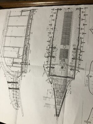
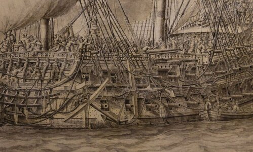
Vasa - 1:65 DeAgostini [COMPLETED BUILD]

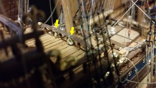
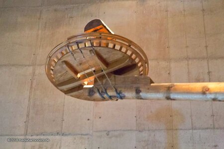
Hi, I have a question about the spritsail topmast. In regards to the VASA, how were the deadeyes of this mast connected to the bowsprit? The following image shows one option, but was wondering for your ship how it was done? Please double click on the thumbnail below to see the full image.
Hello @Jack Sparrow. Here is what I am planning to do:

Stockholm-180323_9137.jpg
 
Thanks John,

Yes, I think its the DS460 (I have the larger one with the tipping table).

Are you talking about the deck planking for the beakhead? If that's what you are referring to I have the image from Landstrom as well as an even more clear one sent to me by Thomas. Not sure if you ever saw the following picture of this portion of the ship. Incredible photo:

View attachment 259024

I doubt I'll be able to do any of this better than you did on your masterful Vasa.
I have, in fact, never seen this photo. It is remarkable for a number of reasons! First of all, what a masterful splice of the new sprit-mast to the old, preserving, I'm sure, as much of the original timber as possible. Also interesting is that Vasa refutes the notion that pin-rails weren't a thing until much later in the 17th C./18th C. Also, those are some horribly challenging seats of "ease?"
 
Thanks Heinrich, Vic, Paul, Daniel, Peter and everyone else who has stopped by.

Vic, I just used a tiny drill bit to create the ends of each slot and then a jewelers saw to join the holes. I finished up the slots using files.

Peter, yes the beakhead is a 3 dimensional marvel - almost a mini-ship model. For all the skilled and experienced modellers out there it would have been routine. For me it has been quite a challenge (and will continue to be so). If I didn't have a real ship to look at in photos I would never have been able to interpret the drawings I am working from. It has given me a new appreciation for those who scratch build the whole ship.

Daniel, I'm glad this post was helpful to you. The DeAg kit does not have the knees or the splash guard at all. Does the Billings kit include those details (well, I guess knees should not be considered a 'detail' but you know what I mean)... It was possible to install the splash guard working from below but precision suffered.
I think I can safely say that this is never routine for any builder, irrespective of experience; it's a super-complicated structure with the convergence of so many elements that can be simultaneously viewed from numerous angles. It is tough! Once again, you are ACES.
 
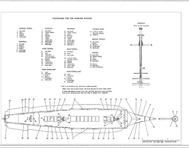
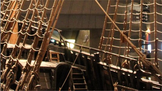
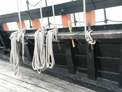
Hubac, your comment regarding pinrails is interesting. I seem to remember a discussion with Fred Hocker about pinrails (link https://warshipvasa.freeforums.net/thread/111/michaels-vasa-update), where he recommends the removal of some pinrails but acknowledges that others were existing on the ship. The beakhead pinrails appear almost definately as in the photograph from Thomas and in the museum. Securing of the vast majority of running lines on the Vasa however is implied by the use of belaying pins inserted into the myriad of 'fixing holes' along the lower bulwark railings, rather than using pinrails. I say 'implied' because that is what is indicated by the Belaying Points diagram produced by the Vasamuseet, (see below, albeit quite old - 1981 and even Fred Hocker recognises some errors in this diagram), but when you examine a picture of the lower bulwark railings of the actual ship (see below again), you do NOT see any holes for the running rigging pins to be secured. This is a conflict I have never been able to resolve.

Rigging+Deck_Secure_Points_English.jpg

Above: Belaying Point diagram produced by Vasamuseet in 1981 implying securing line points using the lower bulwark railings.

Ship_Bulwarks.jpg

Above: Actual image of the Vasa with no evident belaying pin holes along the bulwark railings.

In fact, now I think about it, have I seen ANY belaying pins in ANY of the restoration photographs or evidence of raised material from the ship? Were they used other than in the known pinrails (eg along the beakhead)? Can anyone throw some light on this further?

Regards,
PeterG
 
Peter,
Pinrails (and belaying pins) are a difficult question. In my generic knowledge they did not exist on European and British ships before the end of the 17th century. Building the Sovereign of the Seas I had the same dilemma and after a period of uncertainty I decided not to use them on SoS (and neither on the Soleil Royal stern model). Kit manufacturers are strange species and they do whatever they can to decrease costs by using repetitive items such as belaying pins in the box, irrespective of the era and the style of the ship. And on top of it sometimes they supply CNC'd brass pins which are so much out of normal that I want to scratch myself...
And, actually I saw Vasa in Stockholm and there was no trace of any pin hole in the rails.
János
 
Thanks Janos, this makes a lot of sense, and I know that in my Billing Boats Vasa box, I have maybe 50 wooden belaying pins, so your are right - they have been included in the kit but in fact, if they were not used on the original ship (in the railings anyway), then they are costing themselves by including them!! I thoroughly agree with you regarding brass pins - horrible!!

Now, the next question is, how were the running lines secured around the ship? There are 'kevels' on the bulwarks for the major lines, eg mainsail braces, and other lines go through deck openings to pulleys etc, but for the rest, were they tied off around the railings??? I can only assume this was what was done. This method of securing lines, I would have thought was awkward but it would work.

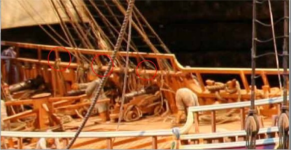
I note that on the 1/10 scale model of the Vasa in the museum, belaying pins through the bulwark railing WERE used (see below) so there is still some contention about their use.

Belaying_Pins.jpg

PeterG
 
Peter,
Pinrails (and belaying pins) are a difficult question. In my generic knowledge they did not exist on European and British ships before the end of the 17th century. Building the Sovereign of the Seas I had the same dilemma and after a period of uncertainty I decided not to use them on SoS (and neither on the Soleil Royal stern model). Kit manufacturers are strange species and they do whatever they can to decrease costs by using repetitive items such as belaying pins in the box, irrespective of the era and the style of the ship. And on top of it sometimes they supply CNC'd brass pins which are so much out of normal that I want to scratch myself...
And, actually I saw Vasa in Stockholm and there was no trace of any pin hole in the rails.
János
Well pinrails and belaying pins were most definitely used on the Dutch Batavia (1628) well before the end of the 17th Century.

kPICT0532.jpg
 
It is my understanding that lines are attached directly to the rails on early 17th century ships. There is no specific evidence when or where belaying pins came into service. Cleats lashed to the shrouds are another place where running rigging was often belayed. Unfortunately, there are no examples of belaying plans for early 17th century ships for us to draw conclusions from, with exception of the Batavia 1628, an isolated example. On my model, I used a combination of the plans Corel provided and those of Vincenzo Lusci developed in 1972. It is important to not accept the plans of earlier modelers like Lusci without doing your own research and comparing their methods with those of others, or with newly discovered sources.

R. C. Anderson:

1633744668093.png

Look at the rear rail on the forecastle for an example of belaying to a rail.
1378 Completed Photo.jpg

Belaying to a rail
1322 Lateen Leech Line Belaying Points.jpg
 
Many thanks Darivs A. I think we are highjacking Paul’s log here a bit, but it is an important discussion. I was always of the thinking that belaying pins were used on the railings, but the evidence (despite the Batavia example), appears to point to securing on the railings instead.

Good contribution and if Anderson alludes to it, it is likely to be the case. Anderson also describes the securing cleats used on shrouds, as you say Darivs.

PeterG
 
I do apologize to Paul if this constitutes hijacking his thread. Whether Vasa had pin rails and belaying pins I do not know. I am merely saying that they were used on Dutch ships and used extensively.

6.jpg

This is Ab Hoving's own model of his 134-foot pinas.

And based on the drawings of Otte Blom and Dik, they were also used on the Zeven Provincien.

008.jpeg
 
Gentlemen, if this build log helps future builders it will have served its highest purpose. I welcome the discussion. From the perspective of a novice I can tell you that I sense that much of what we think we know about early ship building we, in fact, do not know. The raising of the Wasa (and I’ll include the early 16th century Mary Rose in here as well) has challenged some of what were thought to be naval architecture conventions. I can’t help but wonder how much is correct on modern reconstructions and how much is just the application of more ‘modern’ methods to ancient vessels.

As for me, the holes are drilled so pins in the lower rails it will be. It may be wrong but I’m in good company :p.

Plus, I found these close-to-scale pear pins that I think look really good. I own scores of them because I fully intend to break them by the dozen during rigging.

1633785345261.jpeg
 
Gentlemen, if this build log helps future builders it will have served its highest purpose. I welcome the discussion. From the perspective of a novice I can tell you that I sense that much of what we think we know about early ship building we, in fact, do not know. The raising of the Wasa (and I’ll include the early 16th century Mary Rose in here as well) has challenged some of what were thought to be naval architecture conventions. I can’t help but wonder how much is correct on modern reconstructions and how much is just the application of more ‘modern’ methods to ancient vessels.

As for me, the holes are drilled so pins in the lower rails it will be. It may be wrong but I’m in good company :p.

Plus, I found these close-to-scale pear pins that I think look really good. I own scores of them because I fully intend to break them by the dozen during rigging.

View attachment 260650
I’ve never broken one, Paul. But I have pulled up railings and bitts. Have fun with the wrapping and looping of the hanks.
 
Gentlemen, if this build log helps future builders it will have served its highest purpose. I welcome the discussion. From the perspective of a novice I can tell you that I sense that much of what we think we know about early ship building we, in fact, do not know. The raising of the Wasa (and I’ll include the early 16th century Mary Rose in here as well) has challenged some of what were thought to be naval architecture conventions. I can’t help but wonder how much is correct on modern reconstructions and how much is just the application of more ‘modern’ methods to ancient vessels.

As for me, the holes are drilled so pins in the lower rails it will be. It may be wrong but I’m in good company :p.

Plus, I found these close-to-scale pear pins that I think look really good. I own scores of them because I fully intend to break them by the dozen during rigging.

View attachment 260650
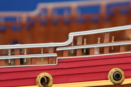
One small problem, Paul. The belaying pins must be removable. The upper railing prevent them from being removed and replaced. That's an essential part of why they are made that way. If you ever decided to remove them entirely, you could cut them flush above and below the lower rail and paint over the bare ends. We wouldn't tell anybody... no, really !
 
One small problem, Paul. The belaying pins must be removable. The upper railing prevent them from being removed and replaced. That's an essential part of why they are made that way. If you ever decided to remove them entirely, you could cut them flush above and below the lower rail and paint over the bare ends. We wouldn't tell anybody... no, really !
Thanks for that keen observation Kurt. The camera angle is a bit misleading. The upper rail is thinner than the lower rail so there is a bit of offset. 90-95% of the pins can be removed/replaced though not all of them. I saw this happening while I was installing the upper rail which is why there are pins already in place rather than adding them later.
 
Thanks for that keen observation Kurt. The camera angle is a bit misleading. The upper rail is thinner than the lower rail so there is a bit of offset. 90-95% of the pins can be removed/replaced though not all of them. I saw this happening while I was installing the upper rail which is why there are pins already in place rather than adding them later.
Ah.... okay.
 
One more thought on the great pin-rail debate. It is well known that Dutch shipwrights were prized by the admiralties of foreign navies. Both the French and Swedish employed Dutch builders, and in fact, the lead carpenter that build Vasa was, himself, Dutch born. If pinrails were a common feature of Dutch ships, I don’t see why they wouldn’t cross-pollinate the navies of other nations. When in doubt, consult the Van de Veldes. Here, Dutch warships after the battle:

00D1C677-B007-429B-ABC4-35BA75F67FF5.jpeg
3041B4B0-6B90-40BA-A229-E1040D2FE877.jpeg

These grissaile drawings are just about as close to photography as one will ever get in the 17th C. They’re a little difficult to see because there is so much detail, but pins are present, piercing the sheer-rails, and beneath the fighting-cloth rails - just as you have them, Paul.
 
Back
Top