Fair enough. They are mid-1660s, at the earliest.
-

Win a Free Custom Engraved Brass Coin!!!
As a way to introduce our brass coins to the community, we will raffle off a free coin during the month of August. Follow link ABOVE for instructions for entering.
-

PRE-ORDER SHIPS IN SCALE TODAY!
The beloved Ships in Scale Magazine is back and charting a new course for 2026!
Discover new skills, new techniques, and new inspirations in every issue.
NOTE THAT OUR FIRST ISSUE WILL BE JAN/FEB 2026
You are using an out of date browser. It may not display this or other websites correctly.
You should upgrade or use an alternative browser.
You should upgrade or use an alternative browser.
Vasa - 1:65 DeAgostini [COMPLETED BUILD]
- Thread starter dockattner
- Start date
- Watchers 147
The detail in these drawings (especially the second one) is mesmerizing. I just wasted half an hour of my life staring at it noting various bits and baubles: the swabs at the fore - the proper anchor knot - the handedness of the lines - the bolts on the hull - the sea of humanity on the deck - the clinker planking on the boat... Imagine what I would see if I knew what I was looking at!One more thought on the great pin-rail debate. It is well known that Dutch shipwrights were prized by the admiralties of foreign navies. Both the French and Swedish employed Dutch builders, and in fact, the lead carpenter that build Vasa was, himself, Dutch born. If pinrails were a common feature of Dutch ships, I don’t see why they wouldn’t cross-pollinate the navies of other nations. When in doubt, consult the Van de Veldes. Here, Dutch warships after the battle:
View attachment 261437
View attachment 261438
These grissaile drawings are just about as close to photography as one will ever get in the 17th C. They’re a little difficult to see because there is so much detail, but pins are present, piercing the sheer-rails, and beneath the fighting-cloth rails - just as you have them, Paul.
Hello Paul
I don't know if you had a chance to view the post I made today on the Soleil Royal but I am facing some challenges on tying the top t the bowsprit
The ZLH kit has a piece similar to the one you are showing above, sitting between the end of the bowsprit and the top but it is not stable at all once glued.
Do you have any recommendation on this?
Thanks
Hi Gilbert. I’m sorry to report that I only showed what is on the ship at the museum. I have not built anything yet on my model.
- Joined
- Oct 9, 2020
- Messages
- 2,222
- Points
- 488

which part exactly is unstable? I can show you what I did, but I am not sure what you are referring to.
Hi Jack Sparrowwhich part exactly is unstable? I can show you what I did, but I am not sure what you are referring to.
The top that sits at the end of the bowsprit is the unstable part.
See picture below what I did.
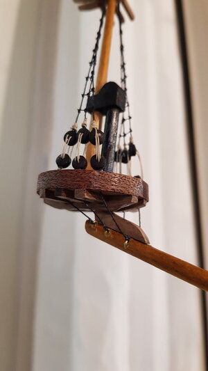
I have now removed the top and shall redo the part between the top and the bowsprit.
I believe if it's a bit wider and is firmly inserted, it should do the trick
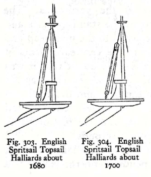
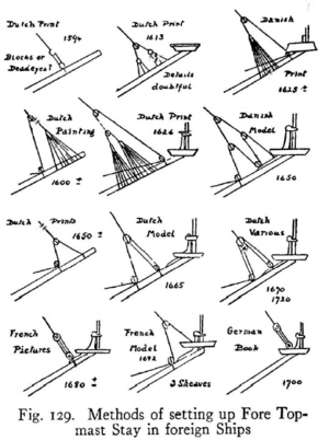
The end of the bowsprit should fit tightly between the trestletrees of the bowsprit top. That provides strong support to the bowsprit top with additional support provided by the chainplates underneath. Sometimes the bowsprit was slightly flattened on the top surface where the knee is fastened to the bowsprit. This provides some transverse support to the knee.
Examples
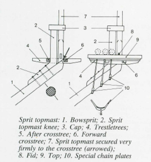
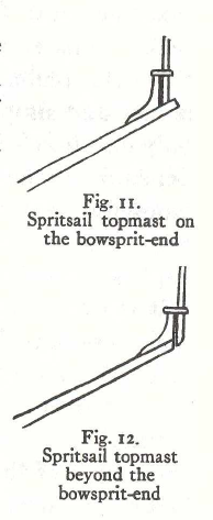
Plethora of bonus rigging info
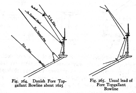
Examples


Plethora of bonus rigging info


Last edited:
Thanks a lot KurtThe end of the bowsprit should fit tightly between the trestletrees of the bowsprit top. That provides strong support to the bowsprit top with additional support provided by the chainplates underneath. Sometimes the bowsprit was slightly flattened on the top surface where the knee is fastened to the bowsprit. This provides some transverse support to the knee.
Examples
View attachment 262052
View attachment 262088
Plethora of bonus rigging info
View attachment 262055
View attachment 262056
View attachment 262064
Very useful
I think it would not too difficult at this point to detach the knee from the top with a razor knife and slide it down, replace the chainplates, and while you're at it, make smaller, blackened eyebolts from wire for those chainplates. They are too large and detract from the other nice details.Thanks a lot Kurt
Very useful
Thanks KurtI think it would not too difficult at this point to detach the knee from the top with a razor knife and slide it down, replace the chainplates, and while you're at it, make smaller, blackened eyebolts from wire for those chainplates. They are too large and detract from the other nice details.
Good idea regarding the eyebolts. Will do
Hey Paul, I am just catching up with your log and as always it's great to follow your excellent progress. I chuckled at your comments in the text box above because that is exactly how I feel some days wading through books and plans showing very confusing "old ways"The detail in these drawings (especially the second one) is mesmerizing. I just wasted half an hour of my life staring at it noting various bits and baubles: the swabs at the fore - the proper anchor knot - the handedness of the lines - the bolts on the hull - the sea of humanity on the deck - the clinker planking on the boat... Imagine what I would see if I knew what I was looking at!
I used brass rod to strengthen my joint there.Hi Jack Sparrow
The top that sits at the end of the bowsprit is the unstable part.
See picture below what I did.
View attachment 262046
I have now removed the top and shall redo the part between the top and the bowsprit.
I believe if it's a bit wider and is firmly inserted, it should do the trick
Thanks PaulI used brass rod to strengthen my joint there.
I believe I have found a solution
I'll post tomorrow in my log file
Hello Dear Friends,
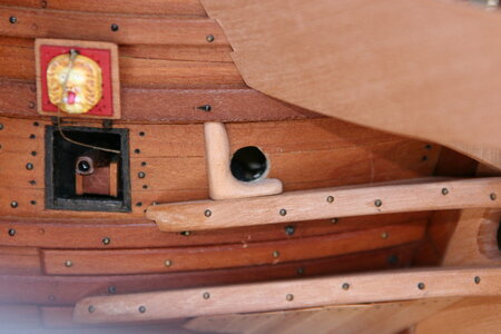
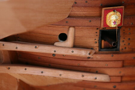
When I last posted I had just completed the knees that support the centerline of the beakhead. Following a brief holiday with my bride work on that area continued in earnest. First up was the simple task of added a rubbing strip for the anchor ropes as they exited the hull. Here is the goal (visible just above the upper knee):
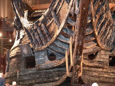
Once again I was struck by how long the simplest tasks take. That said, the second one was completed in half the time of the first one.
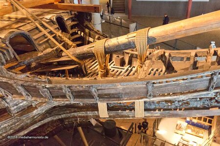
I then took up the floor of the beakhead along with a few other details. For orientation, here is a picture that will give you a rough sense of how the galleon appears on the museum ship.
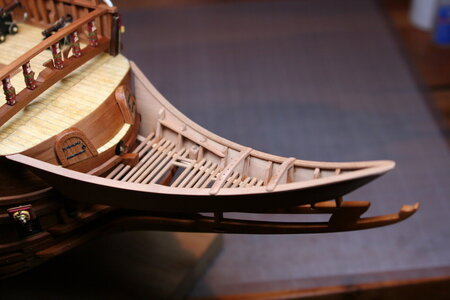
My first step was to install some stringers (or whatever they are called on a ship):
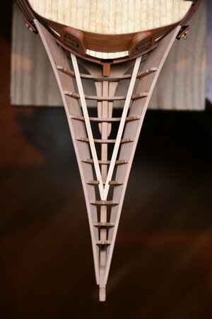
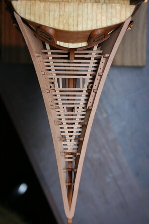
Then the floor beams themselves:
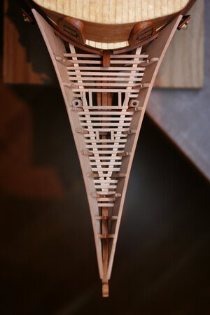
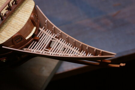
Next, I added the pin rails that run along the bulwark (as well as the cap rail):
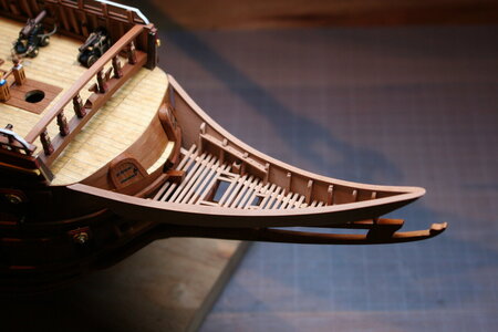
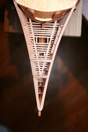
The last step for this weekend was adding the two pin rails that run across the beakhead:
Next up: the steps that lead down to the floor of the galleon. I haven't quite figured out how to fabricate those yet (never mind how to install them). I suspect there will need to be some concessions to scale (which was also necessary on the floor of the galleon).
This scratch construction has challenged me beyond my abilities and experience. My deepest respect to those who work from drawings - you are the true masters of our avocation.
When I last posted I had just completed the knees that support the centerline of the beakhead. Following a brief holiday with my bride work on that area continued in earnest. First up was the simple task of added a rubbing strip for the anchor ropes as they exited the hull. Here is the goal (visible just above the upper knee):

Once again I was struck by how long the simplest tasks take. That said, the second one was completed in half the time of the first one.


I then took up the floor of the beakhead along with a few other details. For orientation, here is a picture that will give you a rough sense of how the galleon appears on the museum ship.

My first step was to install some stringers (or whatever they are called on a ship):

Then the floor beams themselves:


Next, I added the pin rails that run along the bulwark (as well as the cap rail):


The last step for this weekend was adding the two pin rails that run across the beakhead:


Next up: the steps that lead down to the floor of the galleon. I haven't quite figured out how to fabricate those yet (never mind how to install them). I suspect there will need to be some concessions to scale (which was also necessary on the floor of the galleon).
This scratch construction has challenged me beyond my abilities and experience. My deepest respect to those who work from drawings - you are the true masters of our avocation.
Looking great Paul!Hello Dear Friends,
When I last posted I had just completed the knees that support the centerline of the beakhead. Following a brief holiday with my bride work on that area continued in earnest. First up was the simple task of added a rubbing strip for the anchor ropes as they exited the hull. Here is the goal (visible just above the upper knee):
View attachment 263427
Once again I was struck by how long the simplest tasks take. That said, the second one was completed in half the time of the first one.
View attachment 263428 View attachment 263429
I then took up the floor of the beakhead along with a few other details. For orientation, here is a picture that will give you a rough sense of how the galleon appears on the museum ship.
View attachment 263426
My first step was to install some stringers (or whatever they are called on a ship):
View attachment 263430
Then the floor beams themselves:
View attachment 263431
View attachment 263432
Next, I added the pin rails that run along the bulwark (as well as the cap rail):
View attachment 263433
View attachment 263434
The last step for this weekend was adding the two pin rails that run across the beakhead:
View attachment 263435
View attachment 263436
Next up: the steps that lead down to the floor of the galleon. I haven't quite figured out how to fabricate those yet (never mind how to install them). I suspect there will need to be some concessions to scale (which was also necessary on the floor of the galleon).
This scratch construction has challenged me beyond my abilities and experience. My deepest respect to those who work from drawings - you are the true masters of our avocation.
The steps appear to be a one off, each one being different! With these steps I would recommend getting a board that will fit at the proper elevation and be tangent on the sides. This is your support to press a firm type putty in there on top of it. Then remove and use as a template being careful not to distort the putty, hence using a firm type. Or use some impression material… doc!
ps - then there is always paper templates.
Last edited:
It sounds as though congratulations are in order - to you and your new bride!
Oh, and nice beakhead detailing!
Oh, and nice beakhead detailing!
WOW Paul! Your carpentry is exquisite. I love the neat clean lines and joinery.Hello Dear Friends,
When I last posted I had just completed the knees that support the centerline of the beakhead. Following a brief holiday with my bride work on that area continued in earnest. First up was the simple task of added a rubbing strip for the anchor ropes as they exited the hull. Here is the goal (visible just above the upper knee):
View attachment 263427
Once again I was struck by how long the simplest tasks take. That said, the second one was completed in half the time of the first one.
View attachment 263428 View attachment 263429
I then took up the floor of the beakhead along with a few other details. For orientation, here is a picture that will give you a rough sense of how the galleon appears on the museum ship.
View attachment 263426
My first step was to install some stringers (or whatever they are called on a ship):
View attachment 263430
Then the floor beams themselves:
View attachment 263431
View attachment 263432
Next, I added the pin rails that run along the bulwark (as well as the cap rail):
View attachment 263433
View attachment 263434
The last step for this weekend was adding the two pin rails that run across the beakhead:
View attachment 263435
View attachment 263436
Next up: the steps that lead down to the floor of the galleon. I haven't quite figured out how to fabricate those yet (never mind how to install them). I suspect there will need to be some concessions to scale (which was also necessary on the floor of the galleon).
This scratch construction has challenged me beyond my abilities and experience. My deepest respect to those who work from drawings - you are the true masters of our avocation.
Oh my NO! We've been married 36 years. But I do love her as if we were newlyweds! I got a good one!It sounds as though congratulations are in order - to you and your new bride!
Oh, and nice beakhead detailing!


