-

Win a Free Custom Engraved Brass Coin!!!
As a way to introduce our brass coins to the community, we will raffle off a free coin during the month of August. Follow link ABOVE for instructions for entering.
-

PRE-ORDER SHIPS IN SCALE TODAY!
The beloved Ships in Scale Magazine is back and charting a new course for 2026!
Discover new skills, new techniques, and new inspirations in every issue.
NOTE THAT OUR FIRST ISSUE WILL BE JAN/FEB 2026
You are using an out of date browser. It may not display this or other websites correctly.
You should upgrade or use an alternative browser.
You should upgrade or use an alternative browser.
VOC SPIEGELRETOURSCHIP BATAVIA 1628 - KOLDERSTOK 1:72
- Thread starter Heinrich
- Start date
- Watchers 64
-
- Tags
- batavia kolderstok
- Joined
- Jan 9, 2020
- Messages
- 10,566
- Points
- 938

@JScolum
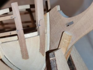
Many thanks for coming to back to me and for the attachments - I now have a much clearer view of what you meant.
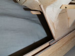
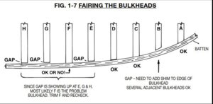
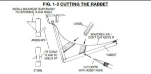
Let me put your mind at ease. NO hull planking has been yet been done and the bulkheads still need to be faired to fit into the rabbet line. The filler blocks at the bow - and wherever else I deem fit - still need to be fitted as well.
Please have a look at Post #6 on Page 1 of my build log. There I explain in detail how the rabbet line was created with accompanying photographs. (For the benefit of the other followers, I will not repeat that whole process, but everything is explained there).
In post #80 on Page 4, I state specifically: "My final aim in the next phase is to start the planking process, but these are still a number of loose ends that need to be tied up before that can begin."
So, I suppose what I have been doing on the stern so far, should actually not be called "planking". More correctly, it is simply "covering" the lower part of the stern with walnut strips of wood to create a realistic visual appearance which is in line with the Lelystadt replica of the Batavia.
I can assure you that courtesy of Hans van Nieuwkoop and Erik Agterhuis of Kolderstok Models, this kit is probably one of the best researched kits on the market.
If you care to elaborate what you mean by "lack of literature" and "Deck boards - Drama", I can attempt to explain that as well.
Any other comments and input are always welcome
Kind regards - Heinrich
- Joined
- Jan 9, 2020
- Messages
- 10,566
- Points
- 938

Dear Model Shipbuilding Friends
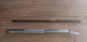
With the arrival of my Exacto knife, it was time to cut open the gunports in the stern assembly. I followed Hans’s recommendation by drilling four small holes in each of the corners of the gunports, after which I traced lines between the holes with the “Exacto”. Then it was simply a case of filing the edges smooth and making sure that the borders line up with that of the rear bulkhead.
After that it was decision time. On the Kolderstok Batavia, the gunports are shown closed, but I had to think carefully about that. As mentioned before, the Haarlem had at least 32 cannons, as opposed to the 24* of the Batavia. For the sake of accuracy it is important to mention that the Kolderstok Batavia is based on the Lelystadt replica which has 24 cannons. On the Kolderstok kits the two bow-chaser cannons (one on either side of the hull), are shown with closed gunports; thus only 22 cannons are visible. Even if I followed the same principle of keeping the two bow cannons closed-up on the Haarlem, it would still leave me 8 cannons short. By installing two rearward-facing stern cannons, I would gain two and would then only have to find mounting space for another 6. Thus the decision was taken. The stern gunports would remain open and the Haarlem would get two stern cannons.
* According to Willem Vos who constructed the Lelystadt replica and the Western Australia Museum, Fremantle, Western Australia, the Batavia originally had 30 cannons: 22 x iron; 6 x bronze and two composite guns. (The composite guns are a most interesting subject and story all on its own.)
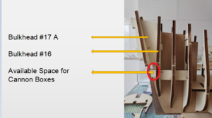
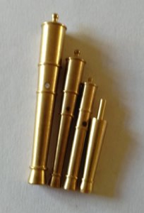
The extremely limted space available between bulkheads 16 and 17 (see the red circle) ruled out any possibility of a conventional cannon/gun carriage combination - it was clear that it would be have to “stick-in” cannons such as those utilised by the Kolderstok on the Batavia in any case. Comparing measurements of one of the cannons to the space available, showed that it could be done - but how?
Borrowing from Kolderstok, I used their cannon box concept, but modified it considerably. Because of the angle of Bulkhead 17, I would have to turn the box upside down and match its sidewalls perfectly to that of the bulkhead. I also opted to build a considerably bigger and MUCH more bulky box, so that if i had to, I could manoeuvre it around to ensure perfect alignment with the cut-open gun ports of the bulkhead. So, back to the box of spare wood where I found a combination of pear and basswood to construct the boxes.
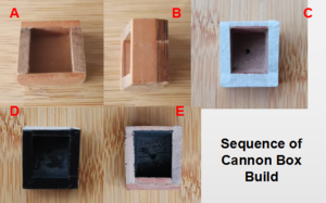
A: Box from the front
B: Box from the top. The angle of the boxes' sides match that of bulkhead #17.
C: After I had carefully measured out and drilled the holes for the cannons, I carefully taped the boxes with masking tape leaving only the inside of the boxes exposed. I didnt want any paint to get on the edges of the box as that had to be glued against the bulkhead for mounting.
D: Boxes sprayed black
E: Masking tape removed and ready for installation.
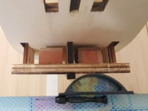
Boxes glued into position - Top View
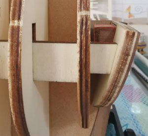
Side View. Box is outlined in red.
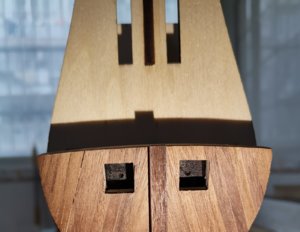
This night-time photograph clearly shows the black insides and drilled holes for the stick-in cannons.
As the whole stern assembly was still only-drifitted at this point, I now needed to start final assembly and for that to be done the cannons had to be installed. But first, the gunports had to receive their red frames. Kolderstok recommends using 3mm x 1mm basswood for this which is then painted red, but here I deviated from instructions by going for the 4mm strips. The second thing was that I didn’t want a brand new Ferrari-red colour. These cannons were essentially blackpowder weapons and anyone who has ever shot anyone of these will know exactly what a messy business it is. After I had sprayed the plank, I waited until it was almost dry and then lightly sanded it with 180 grit sandpaper (on which I had previously strewn some graphite powder) to simulate the root and dirt.
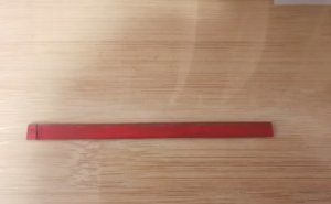
I was quite happy with the result - unmistakably red, but with a nice, faded patina to it - especially around the edges.
The "dirty red" also meant that the cannons would be the focus point at the lower stern. Previously I had decided not to blacken these two cannons. I know this will probably cause an outcry among purists, but seeing that this was my first attempt at a scratch-build, I wanted it to look shiny! This would also be the first identifying characteristic of the Haarlem as opposed to the Batavia - so I wanted to focus on that. After the gunports had received their red borders, the cannons were glued into position, adjusted to their correct depth and angle and left to dry. Finally the lower part of Bulkhead #17 could be glued permanently into position!
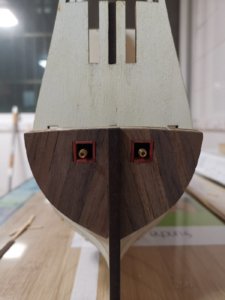
Night-time picture.
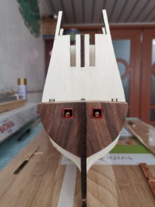
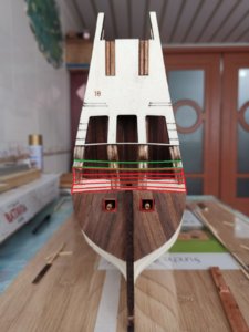
With the cannons installed and the lower part finished it was time to turn my attention to the upper part. As mentioned earlier, the upper part consists of two parts - bulkhead #17A and bulkhead #18. As per the instruction manual, all builders of the Batavia paint the portion of Bulkhead #17A which will be visible when Bulkhead #18 is installed, black. Bulhead #18 contains the three windows and the idea is that the black offers a perception of depth behind the windows. Here, I also deviated from all previous builds by deciding to plank the part of Bulkhead #17A that would be visible through the windows. I knew that I would be creating a ton of extra work for myself - especially around the joints and curves, but the black just did not appeal to me. After the planking was done, it received a good sanding with 180-grit sandpaper and I finished it with a mixture of 30% pure tung oil and 70% turpentine.
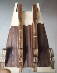
Bulkhead 17A planked.
I have used this combination before when restoring my Bowman Swallow steamboat, and it works wonderfully well. Great care just has to be taken to make sure that the tung oil doesn’t get onto any part that still needs to be glued. With that all finished, Bulkhead #18 was glued into position on the upper part of Bulkhead #17A. With the top part of rear stern assembly completed, the whole top portion could now be glued into the hull and top of Bulkhead #17B. With time, the finish will lighten in colour and lose the shine.
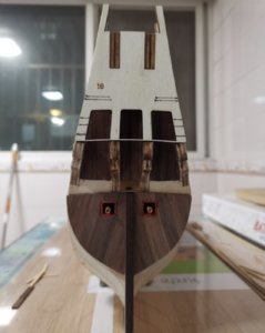
Completed Stern Assembly (night-time)
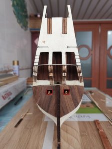
And Daytime.
So with my first-ever scratchbuild "something" and/or kit re-modelling completed ("kit-bashin" it certainly aint), that also brings me to the end of this update. Thank you all so much for your interest and for following.
Kind regards - Heinrich
With the arrival of my Exacto knife, it was time to cut open the gunports in the stern assembly. I followed Hans’s recommendation by drilling four small holes in each of the corners of the gunports, after which I traced lines between the holes with the “Exacto”. Then it was simply a case of filing the edges smooth and making sure that the borders line up with that of the rear bulkhead.
After that it was decision time. On the Kolderstok Batavia, the gunports are shown closed, but I had to think carefully about that. As mentioned before, the Haarlem had at least 32 cannons, as opposed to the 24* of the Batavia. For the sake of accuracy it is important to mention that the Kolderstok Batavia is based on the Lelystadt replica which has 24 cannons. On the Kolderstok kits the two bow-chaser cannons (one on either side of the hull), are shown with closed gunports; thus only 22 cannons are visible. Even if I followed the same principle of keeping the two bow cannons closed-up on the Haarlem, it would still leave me 8 cannons short. By installing two rearward-facing stern cannons, I would gain two and would then only have to find mounting space for another 6. Thus the decision was taken. The stern gunports would remain open and the Haarlem would get two stern cannons.
* According to Willem Vos who constructed the Lelystadt replica and the Western Australia Museum, Fremantle, Western Australia, the Batavia originally had 30 cannons: 22 x iron; 6 x bronze and two composite guns. (The composite guns are a most interesting subject and story all on its own.)

The extremely limted space available between bulkheads 16 and 17 (see the red circle) ruled out any possibility of a conventional cannon/gun carriage combination - it was clear that it would be have to “stick-in” cannons such as those utilised by the Kolderstok on the Batavia in any case. Comparing measurements of one of the cannons to the space available, showed that it could be done - but how?
Borrowing from Kolderstok, I used their cannon box concept, but modified it considerably. Because of the angle of Bulkhead 17, I would have to turn the box upside down and match its sidewalls perfectly to that of the bulkhead. I also opted to build a considerably bigger and MUCH more bulky box, so that if i had to, I could manoeuvre it around to ensure perfect alignment with the cut-open gun ports of the bulkhead. So, back to the box of spare wood where I found a combination of pear and basswood to construct the boxes.

A: Box from the front
B: Box from the top. The angle of the boxes' sides match that of bulkhead #17.
C: After I had carefully measured out and drilled the holes for the cannons, I carefully taped the boxes with masking tape leaving only the inside of the boxes exposed. I didnt want any paint to get on the edges of the box as that had to be glued against the bulkhead for mounting.
D: Boxes sprayed black
E: Masking tape removed and ready for installation.

Boxes glued into position - Top View

Side View. Box is outlined in red.

This night-time photograph clearly shows the black insides and drilled holes for the stick-in cannons.
As the whole stern assembly was still only-drifitted at this point, I now needed to start final assembly and for that to be done the cannons had to be installed. But first, the gunports had to receive their red frames. Kolderstok recommends using 3mm x 1mm basswood for this which is then painted red, but here I deviated from instructions by going for the 4mm strips. The second thing was that I didn’t want a brand new Ferrari-red colour. These cannons were essentially blackpowder weapons and anyone who has ever shot anyone of these will know exactly what a messy business it is. After I had sprayed the plank, I waited until it was almost dry and then lightly sanded it with 180 grit sandpaper (on which I had previously strewn some graphite powder) to simulate the root and dirt.

I was quite happy with the result - unmistakably red, but with a nice, faded patina to it - especially around the edges.
The "dirty red" also meant that the cannons would be the focus point at the lower stern. Previously I had decided not to blacken these two cannons. I know this will probably cause an outcry among purists, but seeing that this was my first attempt at a scratch-build, I wanted it to look shiny! This would also be the first identifying characteristic of the Haarlem as opposed to the Batavia - so I wanted to focus on that. After the gunports had received their red borders, the cannons were glued into position, adjusted to their correct depth and angle and left to dry. Finally the lower part of Bulkhead #17 could be glued permanently into position!

Night-time picture.

With the cannons installed and the lower part finished it was time to turn my attention to the upper part. As mentioned earlier, the upper part consists of two parts - bulkhead #17A and bulkhead #18. As per the instruction manual, all builders of the Batavia paint the portion of Bulkhead #17A which will be visible when Bulkhead #18 is installed, black. Bulhead #18 contains the three windows and the idea is that the black offers a perception of depth behind the windows. Here, I also deviated from all previous builds by deciding to plank the part of Bulkhead #17A that would be visible through the windows. I knew that I would be creating a ton of extra work for myself - especially around the joints and curves, but the black just did not appeal to me. After the planking was done, it received a good sanding with 180-grit sandpaper and I finished it with a mixture of 30% pure tung oil and 70% turpentine.

Bulkhead 17A planked.
I have used this combination before when restoring my Bowman Swallow steamboat, and it works wonderfully well. Great care just has to be taken to make sure that the tung oil doesn’t get onto any part that still needs to be glued. With that all finished, Bulkhead #18 was glued into position on the upper part of Bulkhead #17A. With the top part of rear stern assembly completed, the whole top portion could now be glued into the hull and top of Bulkhead #17B. With time, the finish will lighten in colour and lose the shine.

Completed Stern Assembly (night-time)

And Daytime.
So with my first-ever scratchbuild "something" and/or kit re-modelling completed ("kit-bashin" it certainly aint), that also brings me to the end of this update. Thank you all so much for your interest and for following.
Kind regards - Heinrich
You did a nice job on mounting the canons in the rear. But in times of war it was not really effective to have canons in the stern of the ship. You could not fire it to your enemy at the side of your ship because it is pointing in the wrong direction. The gunports in the stern where only used if the ship was chased. Two of the side canons where moved to the back and shot to try to scare off the enemy. The same goes for the two ports at the bow.
A much easier and more realistic way to put extra canons on your ship is just to place them on the higher decks. By simply cutting extra gun ports in the bulwarks and placing a canon with carriage in it the amount of 24 could be increased to 30 or so.
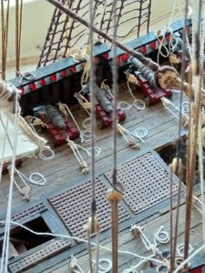
Picture of my model of the Zeven Provinciën (please don't look at the dust on it...):

- Joined
- Jan 9, 2020
- Messages
- 10,566
- Points
- 938

@Kolderstok Dear Hans. Thank you for the kind words and advice. You are absolutely right in everything that you say - however, the Haarlem was indeed equipped with stern cannons which Kapitein Cornelis Simonszoon Van der Veer, actually used during the Action of Mormugão, South of Goa, India against the Portuguese fleet on 30 September 1639.
As to the cannons on the upper deck - that was actually going to be my next question to you - where do you suggest I fit the 6 cannons from the 7P with their carriages? The red squares indicate possible positions of these - the only problem is that they will be partially hidden by the halfdeck. Any other suggestions?
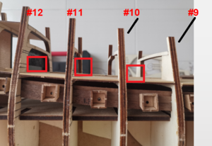
Kind regards - Heinrich
As to the cannons on the upper deck - that was actually going to be my next question to you - where do you suggest I fit the 6 cannons from the 7P with their carriages? The red squares indicate possible positions of these - the only problem is that they will be partially hidden by the halfdeck. Any other suggestions?

Kind regards - Heinrich
Maybe you can also place two (visible) canons on the fore deck?
- Joined
- Jan 9, 2020
- Messages
- 10,566
- Points
- 938

@Kolderstok Good idea Hans! Would that be two in total (one on either side)? Then one more question for now: Does the actual diameter of the 7P cannon correspond to the diameter of the "stick-in" cannons? Are they the same "calibre"?
Heinrich,
I like the amount of thinking, imagineering and visualizing you are doing with your “scratch built, kit bash, adjusted historically” build. Your explanations are great.
Jan
I like the amount of thinking, imagineering and visualizing you are doing with your “scratch built, kit bash, adjusted historically” build. Your explanations are great.
Jan
- Joined
- Jan 9, 2020
- Messages
- 10,566
- Points
- 938

@Pathfinder65 Thank you very much, Jan. I must say, I also enjoy the planning stage.
- Joined
- Jan 9, 2020
- Messages
- 10,566
- Points
- 938

@Kolderstok Thank you Hans. I agree with you, the 32mm is the way to go.
Hello. I would agree with the frame of gun shells embedded under the board .. With a little training it can be made.
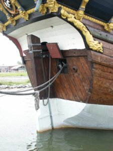
Photo replica - https://www.modelships.de/Museums_and_replicas/Batavia/Photos_Batavia.htm
I keep my fingers crossed for the building!!

Photo replica - https://www.modelships.de/Museums_and_replicas/Batavia/Photos_Batavia.htm
I keep my fingers crossed for the building!!

- Joined
- Jan 9, 2020
- Messages
- 10,566
- Points
- 938

Dear Shipbuilder Friends.
It is great to see such a hive of activity on the forum. I really had to search for my build log!
Here we go with the weekly update: So still continuing work at the stern, the next step was to start the planking the spiegel - and more specifically the hollow part or “Holle Wulf” as it is called. On the Batavia this portion of the stern depicts a painting (see picture below), but seeing that there was no painting on the Haarlem, I wouldn’t have the luxury of “hiding” any planking imperfections underneath paint, I knew that I had to be meticulous when carrying out the planking.
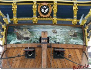
Painting on the "Holle Wulf" or hollow part of the stern of the Batavia.
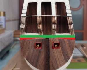
The instructions stipulate that 4mm walnut planks should be used for this. On almost all of the builds I have seen so far, the builders utilise straight planks for the stern as indicated by the green “plank”. The problem with this is that “filler pieces” - cut into somewhat triangular shapes (see the red pieces) - then have to be inserted as indicated on the picture below:
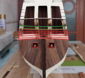
Personally (and this is really just my opinion), this gives the stern somewhat of an “afterthought” look which I didn't like. The only way that the stern could be done properly (again this is in my mind and no reflection on anyone else) was by bending the planks as per the excellent drawing that @Ondras71 was so kind to make for me.
For the first plank I chose a 6mm plank which was then bent according to Glenn Barlow’s method of dipping the plank into hot water, clamping it into position on the plan (so that it follows the correct curvature) and then ironed dry. One the plank has cooled down, it can be removed and will keep its shape permanently.
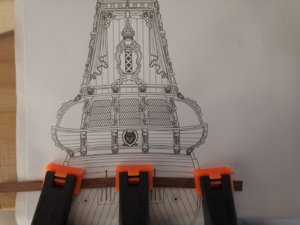
Using the plan as a template, the stern planks are bent accordingly.
With the glue dried, the first plank was laid.
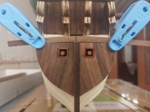
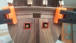
Note the centre mark on the plank. This was used for the correct positioning of the plank and also provided the starting point for the hole of the helm (or "kolderstok"'s connection to the rudder. The first and second planks had to be cut open to create the required opening for the helm.
The first plank was cut after installation on the ship, but on the second plank, I carefully measured the opening and cut it before installation. (Picture above).
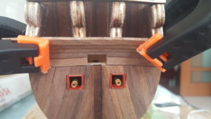
Thereafter it was simply a case of bending each plank individually beforehand before installing it into position. I took great care that no glue residue was left behind on any of the joints and completed the planking of the hollow part of the stern.
Planking process taking place - top and bottom.
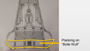
The concave part of the stern or "Bolle Wulf" of the stern (Marked in yellow on the picture below) is left open at this stage and will only be done once the side galleries are in place after the hull planking. This is done so that the planks can be joined accurately to the bottom side of the side galleries.
Thereafter it was just a light sanding with 180 grit sandpaper to see what the stern looked like and I must say, was very happy with the results.
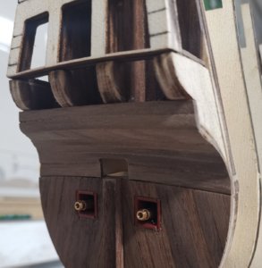
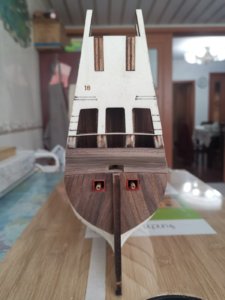
With the stern now completed - as far as I can go up to this point - it is time to turn my attention to the shaping of the bow that will be covered in my next post.
As always - thank you very much for your interest, comments and for following. I trust that you are looking after yourselves and keeping safe.
Warm greetings - Heinrich
It is great to see such a hive of activity on the forum. I really had to search for my build log!
Here we go with the weekly update: So still continuing work at the stern, the next step was to start the planking the spiegel - and more specifically the hollow part or “Holle Wulf” as it is called. On the Batavia this portion of the stern depicts a painting (see picture below), but seeing that there was no painting on the Haarlem, I wouldn’t have the luxury of “hiding” any planking imperfections underneath paint, I knew that I had to be meticulous when carrying out the planking.

Painting on the "Holle Wulf" or hollow part of the stern of the Batavia.
The instructions stipulate that 4mm walnut planks should be used for this. On almost all of the builds I have seen so far, the builders utilise straight planks for the stern as indicated by the green “plank”. The problem with this is that “filler pieces” - cut into somewhat triangular shapes (see the red pieces) - then have to be inserted as indicated on the picture below:

Personally (and this is really just my opinion), this gives the stern somewhat of an “afterthought” look which I didn't like. The only way that the stern could be done properly (again this is in my mind and no reflection on anyone else) was by bending the planks as per the excellent drawing that @Ondras71 was so kind to make for me.

For the first plank I chose a 6mm plank which was then bent according to Glenn Barlow’s method of dipping the plank into hot water, clamping it into position on the plan (so that it follows the correct curvature) and then ironed dry. One the plank has cooled down, it can be removed and will keep its shape permanently.

Using the plan as a template, the stern planks are bent accordingly.
With the glue dried, the first plank was laid.

Note the centre mark on the plank. This was used for the correct positioning of the plank and also provided the starting point for the hole of the helm (or "kolderstok"'s connection to the rudder. The first and second planks had to be cut open to create the required opening for the helm.

The first plank was cut after installation on the ship, but on the second plank, I carefully measured the opening and cut it before installation. (Picture above).
Thereafter it was simply a case of bending each plank individually beforehand before installing it into position. I took great care that no glue residue was left behind on any of the joints and completed the planking of the hollow part of the stern.

Planking process taking place - top and bottom.

The concave part of the stern or "Bolle Wulf" of the stern (Marked in yellow on the picture below) is left open at this stage and will only be done once the side galleries are in place after the hull planking. This is done so that the planks can be joined accurately to the bottom side of the side galleries.

Thereafter it was just a light sanding with 180 grit sandpaper to see what the stern looked like and I must say, was very happy with the results.


With the stern now completed - as far as I can go up to this point - it is time to turn my attention to the shaping of the bow that will be covered in my next post.
As always - thank you very much for your interest, comments and for following. I trust that you are looking after yourselves and keeping safe.
Warm greetings - Heinrich
Heinrich,
That is a great piece of painstaking work. I find plank bending to be a very slow process.
Jan
That is a great piece of painstaking work. I find plank bending to be a very slow process.
Jan


