Aft cabin skylight and vent. Part 2.
I had a change of plan and stopped work on the Forecastle hoodway. And went back to the Aft cabin skylight and vent, with the thought that the changes won’t take long. Well things got off to a good start.
The skylight sides were modified fairly quickly.
View attachment 273981
View attachment 273982
Then I had the bright idea that I could improve the portholes quite a lot from the first attempt and that wouldn’t take long or would it, turns out it would take a while. Using the photo of a couple of portholes on the Lydia Eva as a guide.
View attachment 273983
I machined up some new Brass blanks, then started on making a drilling jig from steel.
View attachment 273984
Next the rotary table was centered, then one axis moved out the correct amount, to start drilling the 6x.7mm holes.
View attachment 273985
The 2 blanks simply go into the jig one at a time, for the first hole to be drilled and have a pin inserted so the position is fixed to start drilling the next hole.
View attachment 273986View attachment 273987View attachment 273988
New holes were drilled in the Skylight to receive the portholes.
View attachment 273989View attachment 273990
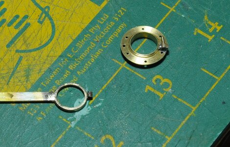
Now the tricky bit, small rings to simulate the outer ring with glass were turned and polished then a small ring was Silver Soldered in place, I used my little trick of a turned down pencil lead to locate the small ring, as I am finding out this is not always a good trick as any carbon from the pencil stops the solder from flowing to places where you want it, although when it works it is good.
View attachment 273991
Next came the hinge pin, when working on small parts it is always best to have them attached to bits you can handle easily until the last minute , this is what I did with the 2 pins I needed to make, Silver Soldering was used again.
View attachment 273992
Then after cutting off and a bit of fileing they were Soft Soldered into place.
View attachment 273993View attachment 273994View attachment 273995
A piece of brass needs to be made up that will be Silver Soldered onto the porthole ring, then shaped into a fork like shape.
View attachment 273996View attachment 273997
You may ask why use Silver Solder the reason is the colour is very similar to brass and when polished it will be hard to tell where the solder is.
View attachment 273999
Once soldered in place a hole was transferred through, then a bit of polishing and cut off, trimmed then some more polishing and cut a slot then some more polishing.
View attachment 274000
Next Job was to make 2 little pins with a ring Silver Soldered on one end, trickier than first thought but I got there.
View attachment 274001View attachment 274002
Infine, inserendo gli oblò nel lucernario in modo abbastanza semplice, trasferisci tutti i fori nel modo giusto, ci è voluto un po' di tempo per sistemare le cose, direi che sono stato abbastanza contento dei miei sforzi fino al giorno dopo non sono riuscito a trovare uno dei perni , non è un problema ne farò un altro, beh ci sono arrivato al 4° tentativo, ancora non ho trovato il perno di fuga!!
Con il nuovo perno in posizione e il gruppo seduto approssimativamente in posizione, ero di nuovo felice.
View attachment 274003View attachment 274004
Dopo ulteriori considerazioni, ho deciso di lasciare spento lo sfiato del fungo perché secondo me non sarebbe sembrato del tutto giusto.
La mia ipotesi è che il Lydia Eva sia un Drifter più grande del Formidable e quindi abbia un lucernario più grande a poppa.
Il prossimo Hoodway di Forecastle.
Questo è tutto per il momento, grazie per aver guardato e letto le mie divagazioni o semplicemente guardando le foto e stai al sicuro.
Saluti,
Stefano.


")


.jpg")
.JPG")
.JPG")
.JPG")
.JPG")
.JPG")
.JPG")
.JPG")
.JPG")

.JPG")
.JPG")
.JPG")

.JPG")
.JPG")

.JPG")
.JPG")
.JPG")
.JPG")
.JPG")
.JPG")
.JPG")


 Rich (PT-2)


.JPG")
.JPG")
.JPG")
.JPG")
.JPG")
.JPG")
.JPG")
.JPG")
.JPG")