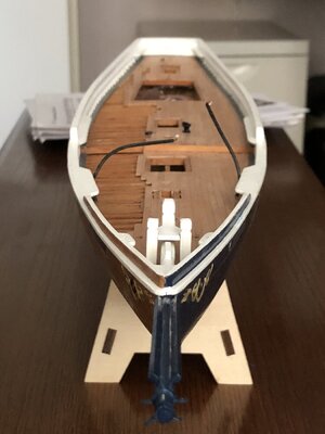
YQ Bluenose by Johan [COMPLETED BUILD]

And a second fitting saw light.
Same process used as for the first fitting, only differences were the diameter, dia 4mm/.157" and 4- instead of 3 eyes.
This is the proces I used:
- Drill a 0,8mm/0,032" hole in a strip of 2mm/0,078" wide. The strips are from the frames in which the etched parts, like the name plates, were held. The edge distances are a matter of opinion, I used 2,5mm/0,098" from the top of the strip.
- Mark the bend line at 4mm/.157" from the top.
- Position a drill bit of 4mm/.157" in a small vise.
- From approx the marked bend line, start bending the strip around the drill bit.
- When the strip is through approx180 degrees, take the strip away from the drill bit and fold the top of the strip through 90 degrees, thus creating the first eye plate.
- Reposition the strip around the drill bit, fold it further towards the folded tip.
- It is not possible to go through a full 360 degrees, but trimming the excess length of the strip and a bit of tweaking will get you the base part of the fitting and your first eye plate.
- Solder the end of the strip to the bottom of the bend of the first eye plate.
- Cut three strips with a similar width as the base part and drill the 0,8mm/0,032" holes. The length of the strips are rather arbitrary, as long as you can clamp and hold them in place during soldering, everything goes.
- Solder the three eye plates to the base strip at 90 degree intervals. This is not as easy as it sounds; the parts are so small, that applying the heat for just a little too long results in previous connections becoming detached.
- Trim the eye plates to whatever shape you like, chamfered, a smooth radius…

Below the result after soldering, I need to tidy up the fitting, but the part is so small, I don't have any idea yet on how to get it smooth and good-looking.

View attachment 335155
A nice second part, Johan. Together with the other, a solid base for all the lines to fit on.
Regards, Peter
 
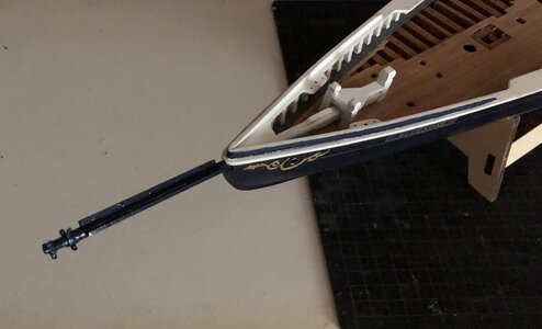
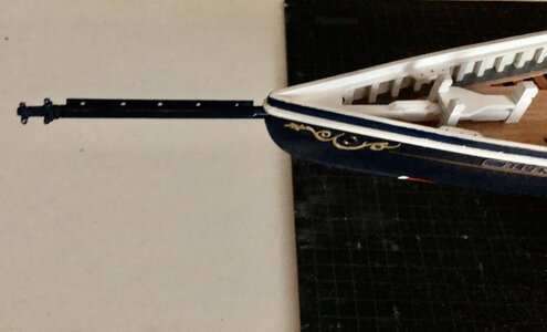
Progress was made again today; the bowsprit, Samson post, bitts and platform were installed.
The bowsprit has become virtually scratch build, the squared base, strips for the jib tie down ropes, the fittings for the standing rigging. Also the height of the bitts and Samson post was adjusted, to allow the jumbo boom to sit lower than indicated by the drawings. The old fotographs of the Bluenose seem to support this decision.
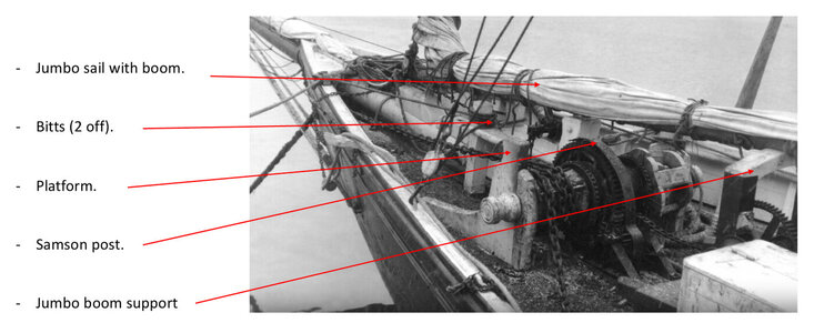
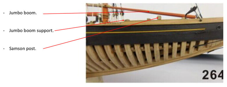
As can be seen quite clearly, the jumbo boom sits rather flat, just clearing the Samson post. The height of the jumbo boom support is such that the boom just remains free from the top of the post.

00E1D0F3-EC8F-472A-9AE5-A6588B088658.jpeg

The pictures in the build instructions show a different orientation of the jumbo boom, which is caused by the proposed height of the Samson post. @Peter Voogt was kind enough to share the dimension he used for the post.
Another interesting point is the height of the Jumbo boom support, which is evidently too low to be able to support the boom. Once arriving at that subject, it will be time for another deviation from the plans.

5ABA449F-5483-4EF0-B2A8-CAF0FCEF38F7.jpeg

Below a couple of shots of the bowsprit, bitts, Samson post and platform.
Now having the fittings in place, I'm not convinced about them. Maybe I have to rethink those fittings... Sick

235F9BF2-4514-4DB3-AED8-C961317B174F.jpeg
03AA1F55-18CC-4A58-991A-9CB3C9B2FDE7.jpeg
BD44A14D-7095-4136-A3B2-D63FD296BEA2.jpeg
 
Last edited:
Progress was made again today; the bowsprit, Samson post, bitts and platform were installed.
The bowsprit has become virtually scratch build, the squared base, strips for the jib tie down ropes, the fittings for the standing rigging. Also the height of the bitts and Samson post was adjusted, to allow the jumbo boom to sit lower than indicated by the drawings. The old fotographs of the Bluenose seem to support this decision.
As can be seen quite clearly, the jumbo boom sits rather flat, just clearing the Samson post. The height of the jumbo boom support is such that the boom just remains free from the top of the post.

View attachment 335534

The pictures in the build instructions show a different orientation of the jumbo boom, which is caused by the proposed height of the Samson post. @Peter Voogt was kind enough to share the dimension he used for the post.
Another interesting point is the height of the Jumbo boom support, which is evidently too low to be able to support the boom. Once arriving at that subject, it will be time for another deviation from the plans.

View attachment 335530

Below a couple of shots of the bowsprit, bitts, Samson post and platform.
Now having the fittings in place, I'm not convinced about them. Maybe I have to rethink those fittings... Sick

View attachment 335514
View attachment 335515
View attachment 335513
great progress my friend, I like the bowsprit, Samson post, bitts and platform:)ThumbsupOkay
 
I don't care for the idea of me diverting your thread from your build so I'll only say that I don't trust my soldering enough to make the "ears" as add-on pieces. I make the entire band plus ears bent from a single brass strip. Your ears are thinner than mine.
 
I don't care for the idea of me diverting your thread from your build so I'll only say that I don't trust my soldering enough to make the "ears" as add-on pieces. I make the entire band plus ears bent from a single brass strip. Your ears are thinner than mine.
I'm not expecting you to follow my build, just interested how you solve these little challenges.
Your favored bending solution is a proven method.
"Your ears are thinner than mine." Yeah and that's worrying me...
 
"Your ears are thinner than mine." Yeah and that's worrying me...
Fascinating! And here I was thinking the thinner ears were a feature, not a bug :D On a prototype spar band what do you think the thickness would be? Maybe 32mm or an inch and a quarter or so?

I imagine tho that the bent ears might be less prone to breakage? A knocked off ear would be hell to solder back on a completed, rigged, and mounted spar.
A sparband of 32mm thick appears to be a little oversized, but for sake of argument; 32mm in real life goes down to 0,4mm/0,0017", which is rather flimsy, in the YQ Bluenose scale. A band thickness of 20mm/0,8" might be more realistic, but maybe one of our esteemed collegues could be more knowledgeable and may be willing to give us a better estimate.
As far as bend vs soldered goes, given the fact one has to apply a very tight bendradius, which might lead to hidden cracks, whereas the soldered ears are really thin and as far as reliability goes, I don't have a clou. Since the ears are so thin, I am worried about the load introduction; one can put quite some load on the standing rigging.
In all I think both options have their specific pro's and con's. Personally I fancy the small soldered fittings over the proposed eyebolts of YQ.
I am considering to run a small test to see how strong a soldered joint really is. Indications sofar let one belief the assembly is relatively rigid.
 
I'm not thinking I'd be all that concerned with part failure. My standing rigging isn't that tight. Tight rigging would bend the boom or the mast long before the solder joint would fail. Or maybe you're worse at soldering than I am imagining ROTF.
Thank or your vote of confidence, Paul. Unfortunately soldering is not my strength.
Although, after soldering one of the ears, I tried to straighten a small axial misalignment, but alas, that didn't work and I had to redo the soldering... So there's hope. (But I'll run a test regardless.)
 
Well whatever we (all of us who make our own) make and method we use, they all look more proper than the heavy out of proportion kit supplied castings which have been kind of the hobby standard since just after WWII. The eyebolts are an improvement over the castings but even with them, wire diameter and loop size can make the scale appearance either passable or clunky.
 
Well whatever we (all of us who make our own) make and method we use, they all look more proper than the heavy out of proportion kit supplied castings which have been kind of the hobby standard since just after WWII. The eyebolts are an improvement over the castings but even with them, wire diameter and loop size can make the scale appearance either passable or clunky.
I wholeheartedly agree. So whatever we choose to do, it will be a nice improvement of our model.
 
Thank or your vote of confidence, Paul. Unfortunately soldering is not my strength.
Although, after soldering one of the ears, I tried to straighten a small axial misalignment, but alas, that didn't work and I had to redo the soldering... So there's hope. (But I'll run a test regardless.)
sorry what diameter is the bowsprit?
 
Back
Top