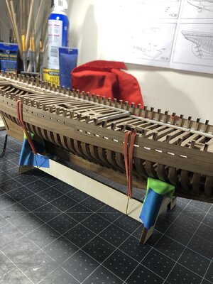
YQ Bluenose Ted R

At this point I have become frustrated.
Hang in there Ted,

I also started with my BN with (much) trial and error.

Many fell, got back up and continued.

My Dutch builders have witnessed the pitfalls that had greater consequences.

I also started again with the frames.

After some setbacks with the masts, I also took a break now to do some other things.

After the summer break I will pick up the BN again.

In addition, if you look at my start date, a considerable amount of time has passed for me. think, Who cares about all the time in the world now……
Regards
Henk
 
Hi Ted, unfortunately frustration is also a part of model building at this level. When I get frustrated (which is common with me), I will take a break from the build sometimes for a good while then come back to it with a much-improved attitude. My bet is just about every one of us on this forum has experienced frustration at some point, I hope you come back to it when the time is right.
Thank you and Rdn for your advice. It took a couple of days for me to come up with a solution. I'll run it pass you guys to see if my idea is logical and hopefully work.
I took out pieces 102 and 103 and checked the alignment wit the beam bearing surface elevation. Fortunately part 102 works really well up to frame 27. (1 frame will need sanding or trimming about 1 mm ).
Frames 31 to 39 are off on both the port and starboard side. In all frame locations they are too high, to the keel.
My intention is to move them down in sequence using part 103 to locate the elevation. The total correction is about 1-2 mm. That should have the deck level and at the correct elevation.
After completing this step I will look as to fairing.
What do you think ?
 
What do you think ?
Well, it sounds as if you are trying for a logical approach, and you are looking for smooth transitional curvature in the fore and aft sections. At this point you are still working on a trial-and-error basis when you say you will move 31-39 to different keel notch locations. It would, in my opinion only, be much better to be 100 percent sure where the ribs are actually supposed to go. But before you can do that you need to be 100% sure you have the ribs correctly assembled by placing them on your paper templates that came with your plans. If you destroyed them during construction, I would be happy to mail you mine, I have no further need for them. If you would like my set just private message me with your mailing address. Hope this helps.
 
I sure would like a nice little sectional drawing at the junction of the forward and aft decks.
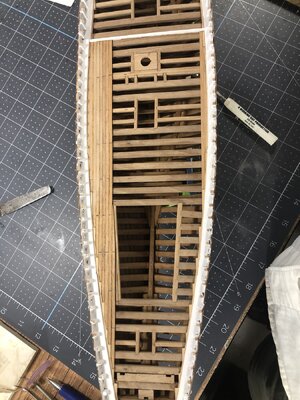
Hi Ted, I went through my photos and these two pictures are all I have. The piece # 45 painted white defines the drop down. I glued it to the adjacent deck beam and it sticks up the thickness of the decking strips so they can butt into it. If I remember correctly piece 45 is itself notched, anyway this was another one of those tough little areas I spent a lot of time studying the plans and others build logs plus a lot of dry fitting until I was satisfied it would work.

IMG_2609.jpgIMG_2629.jpg

Good Luck.
 
Hi Ted, I went through my photos and these two pictures are all I have. The piece # 45 painted white defines the drop down. I glued it to the adjacent deck beam and it sticks up the thickness of the decking strips so they can butt into it. If I remember correctly piece 45 is itself notched, anyway this was another one of those tough little areas I spent a lot of time studying the plans and others build logs plus a lot of dry fitting until I was satisfied it would work.

View attachment 445574View attachment 445575

Good Luck.
Thank you Daniel.
Your suggestion to start over checking the frames is probably the only sure way of getting this right.
I was thinking that if I got th;e deck bearing parts 102/3 in the correct orientation sloping to the transom does it really matter if the difference in elevation between the lower and the two upper decks
If I had to I could extend the bulwark in height the 1-2 mm to make up the difference.
 
Hi Ted. It is good of you to look a few steps ahead, to understand that part of the construction.
I sure would like a nice little sectional drawing at the junction of the forward and aft decks.
Maybe this post from my build log will help, in addition to what Daniel already has posted:
—> Deck Transition Beams <— Click
My result is on later pages, but I made it not conform the instruction.
Beam 45 is shown on plan 8-1, fig 13.
Beam 105 is shown on that plan in fig. 15.
Regards, Peter
 
Last edited:
Hi Ted, in my post above to you I referred you to piece #45 which was wrong. Piece #105 is what defines the exposed drop down that I had painted white. Actually pieces 102 and 103 shown in FIG. 8 on your fold out drawings defines the drop down that all the other pieces rest upon. I'll say this again in a little different way, if you are not 100% sure you have all the ribs correctly assembled and in the right location, you may very well be in for a very difficult time throughout the deck construction.
 
Hi Ted. It is good of you to look a few steps ahead, to understand that part of the construction.

Maybe this post from my build log will help, in addition to what Daniel already has posted:
—> Deck Transition Beams <— Click
My result is on later pages, but I made it not conform the instruction.
Beam 45 is shown on plan 8-1, fig 13.
Beam 105 is shown on that plan in fig. 15.
Regards, Peter
Thank you, got it bookmarked
 
Hi Ted, in my post above to you I referred you to piece #45 which was wrong. Piece #105 is what defines the exposed drop down that I had painted white. Actually pieces 102 and 103 shown in FIG. 8 on your fold out drawings defines the drop down that all the other pieces rest upon. I'll say this again in a little different way, if you are not 100% sure you have all the ribs correctly assembled and in the right location, you may very well be in for a very difficult time throughout the deck construction.
Ted,

Given where you're at right now, I think it's your one shot to iron out the bugs hull-wise.
Like I said before; check every single frame against YQ's drawings. If necessary, rework the frames such that they are matching the drawings, either by removing material, adding material, or (heaven forbid) making yourself some new frames; there's enough scrap material left. Don't move forward until your completely and utterly satisfied that your frames are conforming to specification.
 
Good morning Ted. What a wonderful build log. With Daniel, Johan and Peter giving so much sound advice this has become a manual for any BN builder. So far , you are getting this really good. Nice. Cheers Grant
You hit the nail on the head. The hand holding and guidance these gentlemen have provided this newbie are above and beyond what could even be hoped for.
I'm extremely grateful.
 
Ted,

Given where you're at right now, I think it's your one shot to iron out the bugs hull-wise.
Like I said before; check every single frame against YQ's drawings. If necessary, rework the frames such that they are matching the drawings, either by removing material, adding material, or (heaven forbid) making yourself some new frames; there's enough scrap material left. Don't move forward until your completely and utterly satisfied that your frames are conforming to specification.
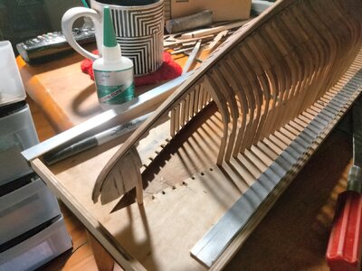
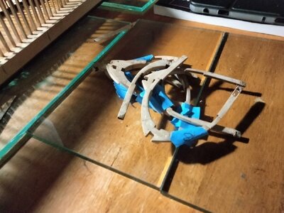
Your last post pitched me over the edge. In going to start removing Silk the frames from the it today and checking them against the drawings.
 
Back
Top